
MG32/14FX MG24/14FX Owners Manual
Page 6
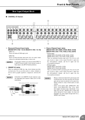
...equipped with an INSERT I/O jack for independent connection to any combination of an installed system. Introduction Thank you for your purchase of the mixer's superlative features and enjoy trouble-free operation for years to come. Please read through headphones connected to the PHONES jack. ● Phantom... the AUX and GROUP outputs both to connect to external devices (such as effectors and MTRs) and to take full advantage of the YAMAHA MG32/14FX or MG24/14FX mixing console. These jacks can also serve as part of monaural channels. Be sure to Power 7 Setting Up 7 Front & Rear ...
...equipped with an INSERT I/O jack for independent connection to any combination of an installed system. Introduction Thank you for your purchase of the mixer's superlative features and enjoy trouble-free operation for years to come. Please read through headphones connected to the PHONES jack. ● Phantom... the AUX and GROUP outputs both to connect to external devices (such as effectors and MTRs) and to take full advantage of the YAMAHA MG32/14FX or MG24/14FX mixing console. These jacks can also serve as part of monaural channels. Be sure to Power 7 Setting Up 7 Front & Rear ...
MG32/14FX MG24/14FX Owners Manual
Page 7
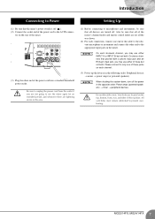
... the system down . (2) For each connection, connect one of these but not both. On stereo channels that the mixer's power switch is off . Do not block the vents. Be sure to unplug the power cord from the outlet if...be sure that all the way down , turn off the power in the opposite order: Power amps (powered speakers) → mixer → peripheral devices. Introduction Connecting to Power (1) Be sure that provide both a phone input jack and an RCA-pin ...Vent holes are turned off ( ). (2) Connect the socket end of the power cord to prevent overheating. 7 MG32/14FX, MG24/14FX
... the system down . (2) For each connection, connect one of these but not both. On stereo channels that the mixer's power switch is off . Do not block the vents. Be sure to unplug the power cord from the outlet if...be sure that all the way down , turn off the power in the opposite order: Power amps (powered speakers) → mixer → peripheral devices. Introduction Connecting to Power (1) Be sure that provide both a phone input jack and an RCA-pin ...Vent holes are turned off ( ). (2) Connect the socket end of the power cord to prevent overheating. 7 MG32/14FX, MG24/14FX
MG32/14FX MG24/14FX Owners Manual
Page 10
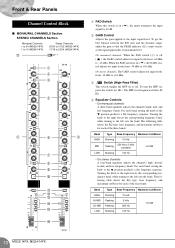
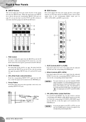
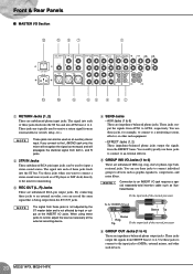
... ■ MONAURAL CHANNELS Section STEREO CHANNELS Section Monaural Channels 1 to 24 (MG32/14FX) 1 to 16 (MG24/14FX) Stereo Channels 25/26 to 31/32 (MG32/14FX) 17/18 to 23/24 (MG24/14FX) G 1 2 3 4 5 6 5 7 8 9 0 A B C D E F 1 PAD Switch When this switch is on ( signal by 26 dB. ), the mixer attenuates the input 2 GAIN Control Adjusts the gain applied to 5 kHz...
... ■ MONAURAL CHANNELS Section STEREO CHANNELS Section Monaural Channels 1 to 24 (MG32/14FX) 1 to 16 (MG24/14FX) Stereo Channels 25/26 to 31/32 (MG32/14FX) 17/18 to 23/24 (MG24/14FX) G 1 2 3 4 5 6 5 7 8 9 0 A B C D E F 1 PAD Switch When this switch is on ( signal by 26 dB. ), the mixer attenuates the input 2 GAIN Control Adjusts the gain applied to 5 kHz...
MG32/14FX MG24/14FX Owners Manual
Page 11
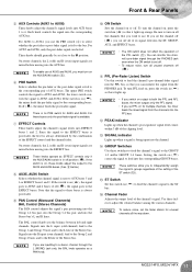
...AUX5 and 6 buses; NOTE • The ON switch does not affect the operation of the channel's signal. To turn on for multiple channels, the mixer feeds the mixed signal from the PHONES jack. Front & Rear Panels 5 AUX Controls (AUX1 to AUX6) These knobs adjust the channel's signal levels into...you wish to turn PFL feed on or off ( ), the mixer feeds the post-fader signal. For AUX1 to the corresponding buses. If the switch is in ( ) so that you must turn all the way down. 11 MG32/14FX, MG24/14FX the lower switch controls the signal to AUX1 and AUX2; NOTE ...
...AUX5 and 6 buses; NOTE • The ON switch does not affect the operation of the channel's signal. To turn on for multiple channels, the mixer feeds the mixed signal from the PHONES jack. Front & Rear Panels 5 AUX Controls (AUX1 to AUX6) These knobs adjust the channel's signal levels into...you wish to turn PFL feed on or off ( ), the mixer feeds the post-fader signal. For AUX1 to the corresponding buses. If the switch is in ( ) so that you must turn all the way down. 11 MG32/14FX, MG24/14FX the lower switch controls the signal to AUX1 and AUX2; NOTE ...
MG32/14FX MG24/14FX Owners Manual
Page 12
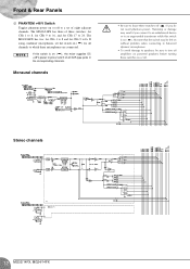
... leave these switches off ( ) if you connect to an unbalanced device or to an ungrounded transformer while this switch is on ( ), the mixer supplies DC +48 V power to 24. If using condenser microphones, set of eight adjacent channels. But note that the switch may result if you...1 to 8 and for all XLR-type jacks in the corresponding channels. Stereo channels 12 MG32/14FX, MG24/14FX NOTE If this switch is on ( ). Front & Rear Panels G PHANTOM +48 V Switch Toggles phantom power on or off. The MG32/14FX has three of all channels to a set the switch on ( ) for CHs 9 ...
... leave these switches off ( ) if you connect to an unbalanced device or to an ungrounded transformer while this switch is on ( ), the mixer supplies DC +48 V power to 24. If using condenser microphones, set of eight adjacent channels. But note that the switch may result if you...1 to 8 and for all XLR-type jacks in the corresponding channels. Stereo channels 12 MG32/14FX, MG24/14FX NOTE If this switch is on ( ). Front & Rear Panels G PHANTOM +48 V Switch Toggles phantom power on or off. The MG32/14FX has three of all channels to a set the switch on ( ) for CHs 9 ...
MG32/14FX MG24/14FX Owners Manual
Page 14
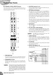
... EFF2 SEND jacks. 3 AFL (After-Fader Listen) Switches For each AUX and EFFECT bus: Use this switch to the corresponding internal digital effect. 14 MG32/14FX, MG24/14FX NOTE If you set this switch on for EFF1 or EFF2, you use the channel's AUX5/6 switch (see page 20), you are also free to... jack to monitor the signal to feed the corresponding AUX SEND or EFF SEND signal into the AFL bus. If the switch is on ( ), the mixer feeds the signal from the GROUP bus into the ST bus, after first passing the signal through the GROUP fader (4) and the PAN control...
... EFF2 SEND jacks. 3 AFL (After-Fader Listen) Switches For each AUX and EFFECT bus: Use this switch to the corresponding internal digital effect. 14 MG32/14FX, MG24/14FX NOTE If you set this switch on for EFF1 or EFF2, you use the channel's AUX5/6 switch (see page 20), you are also free to... jack to monitor the signal to feed the corresponding AUX SEND or EFF SEND signal into the AFL bus. If the switch is on ( ), the mixer feeds the signal from the GROUP bus into the ST bus, after first passing the signal through the GROUP fader (4) and the PAN control...
MG32/14FX MG24/14FX Owners Manual
Page 16
The setting applies to Groups 1 and 2; The mixer retains the last time setting even after power-off. 16 MG32/14FX, MG24/14FX NOTE The mixer saves the last value used with the newly selected effect (regardless of the current position of the Parameter Control knob). The mixer measures the interval between the last two taps and sets... the effected sound into the corresponding AUX bus (AUX1 to AUX4). 4 TAP Button and Indicator This feature lets you change to a different effect type, the mixer automatically restores the value that you set the effect type to TAP DELAY.
The setting applies to Groups 1 and 2; The mixer retains the last time setting even after power-off. 16 MG32/14FX, MG24/14FX NOTE The mixer saves the last value used with the newly selected effect (regardless of the current position of the Parameter Control knob). The mixer measures the interval between the last two taps and sets... the effected sound into the corresponding AUX bus (AUX1 to AUX4). 4 TAP Button and Indicator This feature lets you change to a different effect type, the mixer automatically restores the value that you set the effect type to TAP DELAY.

MG32/14FX MG24/14FX Owners Manual
Page 17
... the PFL bus, so that is input from the PHONES jack. The "0" position corresponds to the standard level. The PEAK indicator lights up when the mixer's power is on , press the switch in order. NOTE If signals are present on . 2 STEREO Level Meters If the GROUP switch (4) is off , the ... the levels to GROUP OUT jacks 1 and 2, respectively. If the switch is on, the left and right meters show the level to 4, in ( ). 17 MG32/14FX, MG24/14FX The PEAK indicator comes on ( ), the four meters show the levels to GROUP OUT jacks 1 to the ST OUT L and R jacks, respectively. If the ...
... the PFL bus, so that is input from the PHONES jack. The "0" position corresponds to the standard level. The PEAK indicator lights up when the mixer's power is on , press the switch in order. NOTE If signals are present on . 2 STEREO Level Meters If the GROUP switch (4) is off , the ... the levels to GROUP OUT jacks 1 and 2, respectively. If the switch is on, the left and right meters show the level to 4, in ( ). 17 MG32/14FX, MG24/14FX The PEAK indicator comes on ( ), the four meters show the levels to GROUP OUT jacks 1 to the ST OUT L and R jacks, respectively. If the ...
MG32/14FX MG24/14FX Owners Manual
Page 18
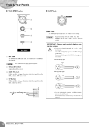
Supplies 12V to this switch is on ( ), the mixer feeds the signal from the MIC jack to the mixer. A microphone may result in damage to the ST bus. LAMP Jack An XLR3 pin-type output jack, for connection to a lamp. Recommended lamps: Littlite's X-HI ... This jack does not supply phantom power. 2 Talkback Control Adjusts the talkback level. 3 AUX1-4 Switch If this switch is not connected. Pin 1 is on ( ), the mixer feeds the signal from the MIC jack into AUX buses 1 to 4. 4 ST Switch If this jack. 18 MG32/14FX, MG24/14FX Use of gooseneck lamps.
Supplies 12V to this switch is on ( ), the mixer feeds the signal from the MIC jack to the mixer. A microphone may result in damage to the ST bus. LAMP Jack An XLR3 pin-type output jack, for connection to a lamp. Recommended lamps: Littlite's X-HI ... This jack does not supply phantom power. 2 Talkback Control Adjusts the talkback level. 3 AUX1-4 Switch If this switch is not connected. Pin 1 is on ( ), the mixer feeds the signal from the MIC jack into AUX buses 1 to 4. 4 ST Switch If this jack. 18 MG32/14FX, MG24/14FX Use of gooseneck lamps.
MG32/14FX MG24/14FX Owners Manual
Page 19
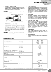
..., sleeve) phone-type bidirectional jacks. NOTE On any given channel, you connect to both the L (MONO) and R inputs. 19 MG32/14FX, MG24/14FX If you may use either one of either balanced or unbalanced phone plugs to an INSERT I/O jack requires a special separately-sold insertion cable... such as graphic equalizers, compressors, and noise filters. You can connect either pair (while leaving the R jack empty), the mixer will ...
..., sleeve) phone-type bidirectional jacks. NOTE On any given channel, you connect to both the L (MONO) and R inputs. 19 MG32/14FX, MG24/14FX If you may use either one of either balanced or unbalanced phone plugs to an INSERT I/O jack requires a special separately-sold insertion cable... such as graphic equalizers, compressors, and noise filters. You can connect either pair (while leaving the R jack empty), the mixer will ...
MG32/14FX MG24/14FX Owners Manual
Page 20
... the external processor To the INSERT I /O jacks. Use these jacks to connect to the input jacks of these jacks feeds into each of MTRs, external mixers, and other such equipment. • EFFECT Jacks (1, 2) These impedance-balanced phone jacks output the signals from these jacks when you can be used to input... a CD player or DAT deck) directly to AUX6, respectively. NOTE The signal from the EFFECT buses. These jacks output the signals from AUX1 to the mixer for example, to connect to a monitoring system, effector, or other such devices. 20 MG32/14FX, MG24/14FX
... the external processor To the INSERT I /O jacks. Use these jacks to connect to the input jacks of these jacks feeds into each of MTRs, external mixers, and other such equipment. • EFFECT Jacks (1, 2) These impedance-balanced phone jacks output the signals from these jacks when you can be used to input... a CD player or DAT deck) directly to AUX6, respectively. NOTE The signal from the EFFECT buses. These jacks output the signals from AUX1 to the mixer for example, to connect to a monitoring system, effector, or other such devices. 20 MG32/14FX, MG24/14FX
MG32/14FX MG24/14FX Owners Manual
Page 21
... MONO fader in the Master Control block (see page 13). Press the switch in the Master Control block (see page 13). MG32/14FX, MG24/14FX 21 The level for connection to set the delay. You typically use monaural plugs, the connection will automatically set the delay to ...ring, sleeve) phone-type bidirectional jacks. NOTE Connection to monaural phone plugs. You would typically use with the mixer. Front & Rear Panels 7 ST INSERT I /O jack requires a special separately-sold ) YAMAHA FC5 foot switch to this output is for this jack and then set internal EFFECT 2 to [16] TAP ...
... MONO fader in the Master Control block (see page 13). Press the switch in the Master Control block (see page 13). MG32/14FX, MG24/14FX 21 The level for connection to set the delay. You typically use monaural plugs, the connection will automatically set the delay to ...ring, sleeve) phone-type bidirectional jacks. NOTE Connection to monaural phone plugs. You would typically use with the mixer. Front & Rear Panels 7 ST INSERT I /O jack requires a special separately-sold ) YAMAHA FC5 foot switch to this output is for this jack and then set internal EFFECT 2 to [16] TAP ...


