
MG32/14FX MG24/14FX Owners Manual
Page 3
...for all volume levels to the product at a high or uncomfortable volume level, since this manual in a safe place for extended periods of the device, or if any openings. &#...near a heater, or in any gaps or openings on the buttons, switches or connectors. 3 MG32/14FX, MG24/14FX To further ensure adequate ventilation, never use this machine. These precautions include, but are located on ...possibility of serious injury or even death from the outlet. Pulling by qualified Yamaha service personnel. Location • When transporting or moving the device, always use two or...
...for all volume levels to the product at a high or uncomfortable volume level, since this manual in a safe place for extended periods of the device, or if any openings. &#...near a heater, or in any gaps or openings on the buttons, switches or connectors. 3 MG32/14FX, MG24/14FX To further ensure adequate ventilation, never use this machine. These precautions include, but are located on ...possibility of serious injury or even death from the outlet. Pulling by qualified Yamaha service personnel. Location • When transporting or moving the device, always use two or...
MG32/14FX MG24/14FX Owners Manual
Page 4
...: send, and ring: return. If the antenna lead-in is not in use , is being affected by Yamaha-Kemble Music (U.K.) Ltd. (3 wires). 4 MG32/14FX, MG24/14FX The performance of components with this product MUST be held responsible for personal use . IMPORTANT: When connecting this product... as switches, volume controls, and connectors, deteriorates over time. In the case of the product during operation. Illustrations in this manual are for Class "B" digital devices. If these requirements provides a reasonable level of their respective owners. Utilize power outlets that your...
...: send, and ring: return. If the antenna lead-in is not in use , is being affected by Yamaha-Kemble Music (U.K.) Ltd. (3 wires). 4 MG32/14FX, MG24/14FX The performance of components with this product MUST be held responsible for personal use . IMPORTANT: When connecting this product... as switches, volume controls, and connectors, deteriorates over time. In the case of the product during operation. Illustrations in this manual are for Class "B" digital devices. If these requirements provides a reasonable level of their respective owners. Utilize power outlets that your...
MG32/14FX MG24/14FX Owners Manual
Page 6
... Appendix 22 Specifications 22 Dimensional Diagrams 25 Block and Level Diagram 26 6 MG32/14FX, MG24/14FX These switches make it easy to selectively monitor the input and output signals through this manual in a safe place. You can provide DC +48 power to all XLR input ... outputs, and four group outputs-for stage monitoring. ● An independently controlled MONO output jack feeds out a mix of the YAMAHA MG32/14FX or MG24/14FX mixing console. Introduction Thank you to connect phantom-powered condenser mics and direct boxes to the PHONES jack. ● Phantom power supply...
... Appendix 22 Specifications 22 Dimensional Diagrams 25 Block and Level Diagram 26 6 MG32/14FX, MG24/14FX These switches make it easy to selectively monitor the input and output signals through this manual in a safe place. You can provide DC +48 power to all XLR input ... outputs, and four group outputs-for stage monitoring. ● An independently controlled MONO output jack feeds out a mix of the YAMAHA MG32/14FX or MG24/14FX mixing console. Introduction Thank you to connect phantom-powered condenser mics and direct boxes to the PHONES jack. ● Phantom power supply...
MG32/14FX MG24/14FX Owners Manual
Page 8
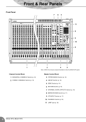
Master Control Block 3 STEREO/MONO Section (p. 13) 4 GROUP Section (p. 14) 5 SEND Section (p. 14) 6 RETURN Section (p. 15) 7 INTERNAL DIGITAL EFFECTS Section (p. 16) 8 METER/PHONES Section (p. 17) 9 2TR INPUT Section (p. 17) 10 TALKBACK Section (p. 18) 11 LAMP Jack (p. 18) 8 MG32/14FX, MG24/14FX Front Panel Front & Rear Panels 7 65 11 8 9 10 8 1 Channel Control Block 1 MONAURAL CHANNELS Section (p. 10) 2 STEREO CHANNELS Section (p. 10) 2 4 3 Note: Within this manual, all panel illustrations show the MG32/14FX panel.
Master Control Block 3 STEREO/MONO Section (p. 13) 4 GROUP Section (p. 14) 5 SEND Section (p. 14) 6 RETURN Section (p. 15) 7 INTERNAL DIGITAL EFFECTS Section (p. 16) 8 METER/PHONES Section (p. 17) 9 2TR INPUT Section (p. 17) 10 TALKBACK Section (p. 18) 11 LAMP Jack (p. 18) 8 MG32/14FX, MG24/14FX Front Panel Front & Rear Panels 7 65 11 8 9 10 8 1 Channel Control Block 1 MONAURAL CHANNELS Section (p. 10) 2 STEREO CHANNELS Section (p. 10) 2 4 3 Note: Within this manual, all panel illustrations show the MG32/14FX panel.

MG32/14FX MG24/14FX Owners Manual
Page 9
Rear Panel Front & Rear Panels 13 Rear Input/Output Block 12 CHANNEL I/O Section (p. 19) 13 MASTER I/O Section (p. 20) 12 Note: Within this manual, all panel illustrations show the MG32/14FX panel. 9 MG32/14FX, MG24/14FX
Rear Panel Front & Rear Panels 13 Rear Input/Output Block 12 CHANNEL I/O Section (p. 19) 13 MASTER I/O Section (p. 20) 12 Note: Within this manual, all panel illustrations show the MG32/14FX panel. 9 MG32/14FX, MG24/14FX
MG32/14FX MG24/14FX Owners Manual
Page 22
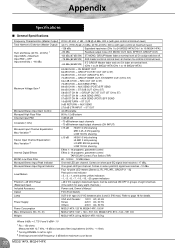
Dimensions (W × H × D) Weight 20 Hz-20 kHz +1 dB, -3 dB @+4 dBu, 600 Ω (with gain control at minimum level) Variation 3 Internal Digital Effects MONO Low Pass Filter Monaural/Stereo Input Peak Indicator Monaural/Stereo Input Signal Indicator Level Meters Phantom +48 VDC Power (Balanced input) Included Accessory Option Lamp Power Supply Power Consumption Max. Appendix Specifications ■ General Specifications Frequency Characteristics (Master Output) Total Harmonic Distortion (Master Output) Hum and Noise (20 Hz - 20 kHz) 1 Input GAIN = Maximum Input PAD = ...
Dimensions (W × H × D) Weight 20 Hz-20 kHz +1 dB, -3 dB @+4 dBu, 600 Ω (with gain control at minimum level) Variation 3 Internal Digital Effects MONO Low Pass Filter Monaural/Stereo Input Peak Indicator Monaural/Stereo Input Signal Indicator Level Meters Phantom +48 VDC Power (Balanced input) Included Accessory Option Lamp Power Supply Power Consumption Max. Appendix Specifications ■ General Specifications Frequency Characteristics (Master Output) Total Harmonic Distortion (Master Output) Hum and Noise (20 Hz - 20 kHz) 1 Input GAIN = Maximum Input PAD = ...
MG32/14FX MG24/14FX Owners Manual
Page 23
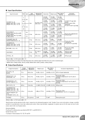
... phone 3 mW 75 mW Stereo phone jack Where 0 dBu = 0.775 V and 0 dBV= 1 V Specifications and descriptions in this owner's manual are for information purposes only. R: cold; S: ground]) REC OUT (L, R) 600 Ω 10 kΩ line -10 dBV (316 mV) +10 dBV...Specifications Input Connector PAD Gain Input Impedance Appropriate Impedance Sensitivity 1 Rated Level Max. Yamaha Corp. reserves the right to maximum gain. 2 MG32/14FX: CH29(L)/30(R), CH31(L)/32(R), MG24/14FX: CH21(L)/22(R), CH23(L)/24(R) ■ Output Specifications Output Connectors Output Appropriate ...
... phone 3 mW 75 mW Stereo phone jack Where 0 dBu = 0.775 V and 0 dBV= 1 V Specifications and descriptions in this owner's manual are for information purposes only. R: cold; S: ground]) REC OUT (L, R) 600 Ω 10 kΩ line -10 dBV (316 mV) +10 dBV...Specifications Input Connector PAD Gain Input Impedance Appropriate Impedance Sensitivity 1 Rated Level Max. Yamaha Corp. reserves the right to maximum gain. 2 MG32/14FX: CH29(L)/30(R), CH31(L)/32(R), MG24/14FX: CH21(L)/22(R), CH23(L)/24(R) ■ Output Specifications Output Connectors Output Appropriate ...

