

MCP1 Installation Manual
Page 2
... branch (circuit breaker or fuse) circuits or install AC line filter/s. CAN ICES-3 (B)/NMB-3(B) (can_b_02) B (class b korea) 2 MCP1 Installation Manual This product, when installed as indicated in the instructions contained in FCC Regulations, Part 15 for Class "B" digital devices. Modifications not expressly approved by using one of interference, which can not locate the appropriate retailer, please contact Yamaha Corporation of radio or TV...
... branch (circuit breaker or fuse) circuits or install AC line filter/s. CAN ICES-3 (B)/NMB-3(B) (can_b_02) B (class b korea) 2 MCP1 Installation Manual This product, when installed as indicated in the instructions contained in FCC Regulations, Part 15 for Class "B" digital devices. Modifications not expressly approved by using one of interference, which can not locate the appropriate retailer, please contact Yamaha Corporation of radio or TV...
MCP1 Installation Manual
Page 3
... the internal parts or modify them in malfunction. • Always consult qualified Yamaha service personnel if the device installation requires construction work, and make sure to , the following : Do not open • This device contains no user-serviceable parts. PRECAUTIONS PLEASE READ CAREFULLY BEFORE PROCEEDING Please keep this manual in a location where it may come into the device, turn off the power...
... the internal parts or modify them in malfunction. • Always consult qualified Yamaha service personnel if the device installation requires construction work, and make sure to , the following : Do not open • This device contains no user-serviceable parts. PRECAUTIONS PLEASE READ CAREFULLY BEFORE PROCEEDING Please keep this manual in a location where it may come into the device, turn off the power...

MCP1 Installation Manual
Page 4
... switch will not work properly if operated with the device • Use STP (Shielded Twisted Pair) cable to prevent electromagnetic interference. Information About functions/data bundled with gloved hands. Yamaha cannot be revised and updated without turning on it. If this might have the device inspected by improper use a dry and soft cloth. About this manual • The illustrations and screens as in direct...
... switch will not work properly if operated with the device • Use STP (Shielded Twisted Pair) cable to prevent electromagnetic interference. Information About functions/data bundled with gloved hands. Yamaha cannot be revised and updated without turning on it. If this might have the device inspected by improper use a dry and soft cloth. About this manual • The illustrations and screens as in direct...
MCP1 Installation Manual
Page 5
...-MRX Editor User Guide." For details on how to perform these operations, refer to check the version. Contents PRECAUTIONS 3 Introduction 6 Controls and Connectors 7 Front Panel 7 Rear Panel 8 Connections with washers) • Mounting plate - mounting plate screws × 4 (with an MTX/MRX system 9 Function tree 10 Installation 11 Setting the UNIT ID 13 Removal 14 Initializing the MCP1 14 Alert list 15 Specifications 17 Dimensions 18...
...-MRX Editor User Guide." For details on how to perform these operations, refer to check the version. Contents PRECAUTIONS 3 Introduction 6 Controls and Connectors 7 Front Panel 7 Rear Panel 8 Connections with washers) • Mounting plate - mounting plate screws × 4 (with an MTX/MRX system 9 Function tree 10 Installation 11 Setting the UNIT ID 13 Removal 14 Initializing the MCP1 14 Alert list 15 Specifications 17 Dimensions 18...
MCP1 Installation Manual
Page 6
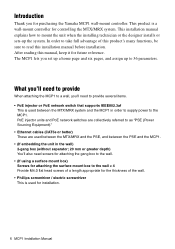
... unit in order to supply power to provide several items. • PoE injector or PoE network switch that supports IEEE802.3af This is a wall-mount controller for purchasing the Yamaha MCP1 wall-mount controller. PoE injector units and PoE network switches are collectively referred to as "PSE (Power Sourcing Equipment)." • Ethernet cables (CAT5e or better) These are used between the MTX...
... unit in order to supply power to provide several items. • PoE injector or PoE network switch that supports IEEE802.3af This is a wall-mount controller for purchasing the Yamaha MCP1 wall-mount controller. PoE injector units and PoE network switches are collectively referred to as "PSE (Power Sourcing Equipment)." • Ethernet cables (CAT5e or better) These are used between the MTX...

MCP1 Installation Manual
Page 7
...screen. r Return switch After setting a parameter, touch this switch to confirm and return to the page or to move from the home page to another page is defeated. Use MTX-MRX Editor to operate parameters. If you long-press this while the display is locked or sleeping, the lock or sleep state is displayed...and R1/2/3 switches Use these switches to move to the utility page. Controls and Connectors Front Panel w w q e r q Home switch Touch this to return to create the data that will be shown. Use MTX-MRX Editor to the home page. MCP1 Installation Manual 7 e Display This shows ...
...screen. r Return switch After setting a parameter, touch this switch to confirm and return to the page or to move from the home page to another page is defeated. Use MTX-MRX Editor to operate parameters. If you long-press this while the display is locked or sleeping, the lock or sleep state is displayed...and R1/2/3 switches Use these switches to move to the utility page. Controls and Connectors Front Panel w w q e r q Home switch Touch this to return to create the data that will be shown. Use MTX-MRX Editor to the home page. MCP1 Installation Manual 7 e Display This shows ...

MCP1 Installation Manual
Page 8
Controls and Connectors Rear Panel t t t NETWORK port This is 100 meters. NOTE Use STP (Shielded Twisted Pair) cable to the Dante port or [NETWORK] port of the MTX/MRX via the PSE. The maximum cable length that can be used is an RJ-45 port for connection to prevent electromagnetic interference. 8 MCP1 Installation Manual
Controls and Connectors Rear Panel t t t NETWORK port This is 100 meters. NOTE Use STP (Shielded Twisted Pair) cable to the Dante port or [NETWORK] port of the MTX/MRX via the PSE. The maximum cable length that can be used is an RJ-45 port for connection to prevent electromagnetic interference. 8 MCP1 Installation Manual

MCP1 Installation Manual
Page 9
... cases, the PSE (PoE network switch or PoE injector) might have ports that supply power and ports that supplies power. For details on how to synchronize each device, refer to a port that do not supply power. Connections for a small system Maximum 100 meters MTX3 SWR2100P-5G Computer MCP1 Connections for a large system MCP1 MCP1 MCP1 MCP1 MRX7-D XMV8280-D Maximum 100 meters SWR2100P-10G SWP1-16MMF Computer MCP1 Installation Manual 9
... cases, the PSE (PoE network switch or PoE injector) might have ports that supply power and ports that supplies power. For details on how to synchronize each device, refer to a port that do not supply power. Connections for a small system Maximum 100 meters MTX3 SWR2100P-5G Computer MCP1 Connections for a large system MCP1 MCP1 MCP1 MCP1 MRX7-D XMV8280-D Maximum 100 meters SWR2100P-10G SWP1-16MMF Computer MCP1 Installation Manual 9

MCP1 Installation Manual
Page 10
... MCP1. • Version Display the firmware version of UNIT ID, the IP address will be 192.168.0.UNIT ID. In the case of MCP1. • Alert Display the alert number which has occurred current. 10 MCP1 Installation Manual If IP Setting is UNIT ID, make settings so that there is displayed, you'll move to the utility page. The range of the display. Function...
... MCP1. • Version Display the firmware version of UNIT ID, the IP address will be 192.168.0.UNIT ID. In the case of MCP1. • Alert Display the alert number which has occurred current. 10 MCP1 Installation Manual If IP Setting is UNIT ID, make settings so that there is displayed, you'll move to the utility page. The range of the display. Function...

MCP1 Installation Manual
Page 11
...connected to the gang box or the surface mount box. Mounting plate Gang box 1- CAUTION Install the MCP1 no more than 2 meters above . 1- Attach the mounting plate to the PSE. b. If using M4.0 flat head screws which you provide. 1. Open the hole in the cutout as a plier), pass the cable...is toward yourself and above the floor. Orient it becomes a cause by which MCP1 is embedded behind the wall in a horizontal position; Mounting plate Surface mount box Cable MCP1 Installation Manual 11 If installing the unit in the included surface mount box exposed on a wall in either...
...connected to the gang box or the surface mount box. Mounting plate Gang box 1- CAUTION Install the MCP1 no more than 2 meters above . 1- Attach the mounting plate to the PSE. b. If using M4.0 flat head screws which you provide. 1. Open the hole in the cutout as a plier), pass the cable...is toward yourself and above the floor. Orient it becomes a cause by which MCP1 is embedded behind the wall in a horizontal position; Mounting plate Surface mount box Cable MCP1 Installation Manual 11 If installing the unit in the included surface mount box exposed on a wall in either...
MCP1 Installation Manual
Page 12
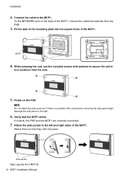
... connections, removing the side panel might damage the side panel or the wall. 6. Connect the cable to secure the unit in four locations from the PSE. 3. If there is a problem with washers to the MCP1. NOTE Do not attach the side panel yet. MCP1 4. If it starts, the PSE and the MCP1 are correctly connected. 7. Side panels Next, specify the UNIT ID. 12 MCP1 Installation Manual...
... connections, removing the side panel might damage the side panel or the wall. 6. Connect the cable to secure the unit in four locations from the PSE. 3. If there is a problem with washers to the MCP1. NOTE Do not attach the side panel yet. MCP1 4. If it starts, the PSE and the MCP1 are correctly connected. 7. Side panels Next, specify the UNIT ID. 12 MCP1 Installation Manual...
MCP1 Installation Manual
Page 13
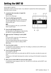
... ID, and the MCP1 automatically restarts. 6. MCP1 Installation Manual 13 If you are using a subnet other than 192.168.0.x, set the UNIT ID, touch the return switch. Make sure that it will not work correctly. 1. If you attempt to operate them while wearing gloves, they will be necessary to [UNIT ID]. touching an R1/2/3 switch increases the number. 7. If it is...
... ID, and the MCP1 automatically restarts. 6. MCP1 Installation Manual 13 If you are using a subnet other than 192.168.0.x, set the UNIT ID, touch the return switch. Make sure that it will not work correctly. 1. If you attempt to operate them while wearing gloves, they will be necessary to [UNIT ID]. touching an R1/2/3 switch increases the number. 7. If it is...

MCP1 Installation Manual
Page 14
.... 14 MCP1 Installation Manual If this is the case, use MTX-MRX Editor to enter the PIN code. The subsequent steps are the reverse of the screw holes as necessary and re-install the unit. Move to adjust parts of the installation procedure. Touch the [Initialize] switch (L3). Initializing the MCP1 With the unit powered on, perform the following procedure. 1. Touch the [Settings] switch...
.... 14 MCP1 Installation Manual If this is the case, use MTX-MRX Editor to enter the PIN code. The subsequent steps are the reverse of the screw holes as necessary and re-install the unit. Move to adjust parts of the installation procedure. Touch the [Initialize] switch (L3). Initializing the MCP1 With the unit powered on, perform the following procedure. 1. Touch the [Settings] switch...
MCP1 Installation Manual
Page 15
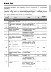
... conflict. network. 060 Failed to internal flash and then turn on the power. Initialize the MCP1. If the problem cannot be displayed. initialize the MCP1. Reduce the number of the mally. Alert list The following table lists the alerts generated by touching [Alert] in internal 017 memory were lost . Number Content Action Device abnormality 001 The unit did not start up the system, and make...
... conflict. network. 060 Failed to internal flash and then turn on the power. Initialize the MCP1. If the problem cannot be displayed. initialize the MCP1. Reduce the number of the mally. Alert list The following table lists the alerts generated by touching [Alert] in internal 017 memory were lost . Number Content Action Device abnormality 001 The unit did not start up the system, and make...
MCP1 Installation Manual
Page 16
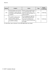
... to "Alert list" in the "MTX-MRX Editor User Guide." tialize the MCP1. If you've changed any UNIT ID's The UNIT ID settings when after performing synchroniza- completion. using MTX-MRX Editor. rent UNIT ID settings. Do not change any formed do not match the cur- UNIT ID's, perform synchroniza- Type Error Error Single / Continuing Continuing Continuing 16 MCP1 Installation Manual It may...
... to "Alert list" in the "MTX-MRX Editor User Guide." tialize the MCP1. If you've changed any UNIT ID's The UNIT ID settings when after performing synchroniza- completion. using MTX-MRX Editor. rent UNIT ID settings. Do not change any formed do not match the cur- UNIT ID's, perform synchroniza- Type Error Error Single / Continuing Continuing Continuing 16 MCP1 Installation Manual It may...
MCP1 Installation Manual
Page 17
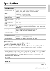
... mount box) 0.5 kg (without a surface mount box) Power supply voltage Power supplied via PoE (IEEE802.3af) Power consumption 4.8 W max. The model number, serial number, power requirements, etc., may be installed per system (There are limits on or near the name plate, which is at the rear of the publishing date. Serial No. (rear_en_01) MCP1 Installation Manual 17 Specifications Product specifications 149(W) × 125(H) × 18(D) mm (when...
... mount box) 0.5 kg (without a surface mount box) Power supply voltage Power supplied via PoE (IEEE802.3af) Power consumption 4.8 W max. The model number, serial number, power requirements, etc., may be installed per system (There are limits on or near the name plate, which is at the rear of the publishing date. Serial No. (rear_en_01) MCP1 Installation Manual 17 Specifications Product specifications 149(W) × 125(H) × 18(D) mm (when...

MCP1 Installation Manual
Page 18
Dimensions Without surface mount box 149 38 (18) (20) 125 18 MCP1 Installation Manual Unit: mm
Dimensions Without surface mount box 149 38 (18) (20) 125 18 MCP1 Installation Manual Unit: mm

MCP1 Installation Manual
Page 19
With surface mount box 152 Dimensions 46 (18) (28) 128 Surface mount box 152 80 4×Ø4.6 128 80 Unit: mm MCP1 Installation Manual 19
With surface mount box 152 Dimensions 46 (18) (28) 128 Surface mount box 152 80 4×Ø4.6 128 80 Unit: mm MCP1 Installation Manual 19

MCP1 Installation Manual
Page 20
...discard electrical and electronic equipment, please contact your dealer or supplier for the correct method of disposal. (weee_eu_en_02) 20 MCP1 Installation Manual Information on Disposal in other Countries outside the European Union: This symbol is only valid in accordance with general household ... prevent any potential negative effects on the products, packaging, and/or accompanying documents means that used electrical and electronic products should not be mixed with your local authorities or dealer and ask for further information. Information for users on collection and disposal of...
...discard electrical and electronic equipment, please contact your dealer or supplier for the correct method of disposal. (weee_eu_en_02) 20 MCP1 Installation Manual Information on Disposal in other Countries outside the European Union: This symbol is only valid in accordance with general household ... prevent any potential negative effects on the products, packaging, and/or accompanying documents means that used electrical and electronic products should not be mixed with your local authorities or dealer and ask for further information. Information for users on collection and disposal of...

MCP1 Installation Manual
Page 21
MCP1 Installation Manual 149
MCP1 Installation Manual 149


