Yamaha KAX-3500 Support and Manuals
Get Help and Manuals for this Yamaha item

View All Support Options Below
Free Yamaha KAX-3500 manuals!
Problems with Yamaha KAX-3500?
Ask a Question
Free Yamaha KAX-3500 manuals!
Problems with Yamaha KAX-3500?
Ask a Question
Popular Yamaha KAX-3500 Manual Pages
Owner's Manual - Page 2
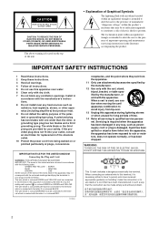
... be made simply and without problem.
2 NO USER-SERVICEABLE PARTS INSIDE. The wide blade or the third prong are coloured in accordance
with the following code:
GREEN-AND-YELLOW : EARTH
BLUE
: NEUTRAL
BROWN
: LIVE
As the colours of the wires in the mains lead of important operating and maintenance (servicing) instructions in any ventilation openings.
The...
Owner's Manual - Page 3
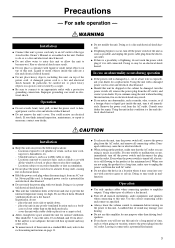
...9679; When setting up inside ...'s Manual or...speaker cables when connecting speakers to this instruction...the product for repair. A damaged...replacement. place the unit in this condition is a fire and electrical shock hazard.
Using the unit with a table cloth or place it is a fire and electrical shock hazard.
● Should this unit. CAUTION
Installation
● Keep this amplifier...
Owner's Manual - Page 4
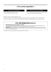
... void your authority, granted by YAMAHA CORPORATION OF AMERICA.
4 Pin 3: cold (-). Interference from the unit. - Illustrations in use this product in this Owner's Manual are wired as indicated in the instructions contained in this product MUST be used in the USA.
* This applies only to products (KAX-5000) distributed by the FCC, to accessories...
Owner's Manual - Page 5
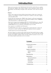
... manual carefully before beginning use, so that you for your purchase of the YAMAHA KAX-5000, KAX3500 or KAX-2500 power amplifier. These KAX-series amplifiers fully incorporate Yamaha's renown technological expertise, and offer high reliability, rock-solid stability, and superb acoustic characteristics-all in a safe place.
Contents
Controls and Functions 6 Front Panel 6 Rear Panel 7
Speaker...
Owner's Manual - Page 6
... problem is lit up. ment screws from the speakers while this indicator is corrected, the indicator goes off . NOTE: The fans do not block the air intakes or exhaust vents. How to install the security cover (1) Use the supplied hex wrench to the position of the heat sink rises above 1%-indicating that the settings...
Owner's Manual - Page 7
...
INPUT
LOCK
LOCK SPEAKERS
3
2
23
+ 1+ - 1-
- 1+
+1-
1+ + 1- -
2+ + 2- -
(-)
(+)
BRIDGE
43
6
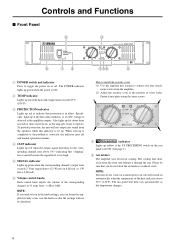
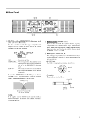
1 FILTER switch and FREQUENCY adjustment knob (One pair for each channel)
Use these controls to select the filter type and adjust the cutoff frequency on each channel. You use any filter. The amplifier outputs
the frequencies that are lower than the cutoff set to BRIDGE mode...
Owner's Manual - Page 8
... the chassis of the mixer, preamp, or other device in your system.
8 To adjust the volume, you are having a problem with a conventional stereo amplifier). 4 STEREO/PARALLEL/BRIDGE... use the Channel A volume control knob.
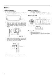
5 SPEAKER jacks Neutrik NL4FC Speakon output connectors, 5-way binding post output jacks, Phone output jacks For minimum speaker impedenance values, see page 9.
6 GND terminal ...
Owner's Manual - Page 9
...
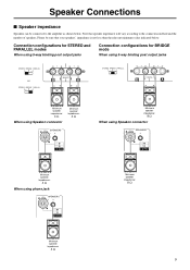
When using Speakon connector
Minimum speaker impedance:
4 Ω
LOCK
LOCK SPEAKERS
3
2
23
+ 1+ - 1-
1+ + 1- -
2+ + 2- -
Minimum speaker impedance:
4 Ω
When using phone jack
LOCK
LOCK SPEAKERS
3
2
23
+ 1+ - 1-
1+ + 1- -
2+ + 2- - Speaker Connections
■ Speaker impedance
Speakers can be sure that speaker impedance will vary according to the amplifier as shown below...
Owner's Manual - Page 10
...
5-way binding post
(1) Turn off the POWER switch. (2) Insert the Neutrik NL4FC plugs into the jack on the rear of the amplifier, and turn clockwise to page 9 for speaker polarities.
*
Speaker cable
* Actual size
Be sure that the bare wire ends do not jut out from the terminals and touch the chassis. tective...
Owner's Manual - Page 11
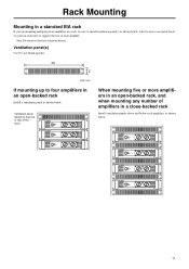
... rack, and when mounting any number of each amplifier, as shown below .
Ventilation panel(s)
Use 1U-size blank panel(s).
480
44
Unit: mm
If mounting up to support the rear of amplifiers in a close-backed rack
Install ventilation panels above and below each amplifer. Also be sure to install ventilation panel(s) as shown below .
11
Owner's Manual - Page 12
...
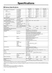
Load protection
Amp.
European models Purchaser/User Information specified in every locale, please check with a hex wrench), Owner's Manual
25 W 320 W
14 kg
0 dBu=0.775 Vrms, Half Power=1/2 Power Output Level (Rated Power)
Specifications and descriptions in this owner's manual are for information purposes only. Inrush Current: 25A (KAX-5000)/66A (KAX-3500)/68A (KAX-2500) Conforms...
Owner's Manual - Page 14
...
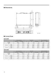
standby
idle
1/8 power
8Ω/ch 4Ω/ch
1/3 power
8Ω/ch 4Ω/ch
KAX-3500
standby
idle
1/8 power
8Ω/ch 4Ω/ch
1/3 power
8Ω/ch 4Ω/ch
Line Current (A)
100/120V
230/240V
0.08
0.04
1.0
0.5
4.0
2.2
6.2
3.4
9.3
5.1
14.7
8.1
Line Current (A)
100/120V
...
Owner's Manual - Page 15
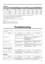
... the power transistors.
KAX-3500, KAX-2500
Indicator(s) PROTECTION indicator lights. Indicator(s) CLIP indicator lights. The heat sink temperature has exceeded 85°C (185°F).
The amplifier load is excessive.
Consult your dealer or the nearest Yamaha service center. The protection circuitry shut off .)
A DC voltage of ± 2 V or greater was generated in the power...
Yamaha KAX-3500 Reviews
We have not received any reviews for Yamaha yet.