Yamaha KAX-2500 Support and Manuals
Get Help and Manuals for this Yamaha item

View All Support Options Below
Free Yamaha KAX-2500 manuals!
Problems with Yamaha KAX-2500?
Ask a Question
Free Yamaha KAX-2500 manuals!
Problems with Yamaha KAX-2500?
Ask a Question
Popular Yamaha KAX-2500 Manual Pages
Owner's Manual - Page 2
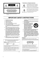
... when unused for replacement of uninsulated "dangerous voltage" within an equilateral triangle is intended to alert the user to rain or moisture, does not operate normally, or has been dropped. The wires in the literature accompanying the product.
Servicing is coloured GREEN-and-YELLOW must be made simply and without problem.
2
Install in any...
Owner's Manual - Page 3
... you think internal inspection, maintenance, or repair is a potential fire and electrical shock hazard.
● Do not touch the power plug with all musical instruments, audio equipment, and speakers when connecting to the rack mounting instructions on the dedicated rack), -
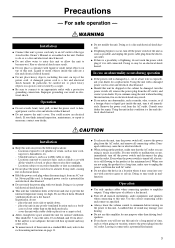
WARNING
Installation
● Connect this unit for a replacement. A damaged power cord is necessary...
Owner's Manual - Page 4
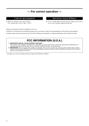
... this manual are wired as indicated in the instructions contained in this product in use only high quality shielded cables. Follow all installation instructions. Always turn the power off when the amplifier is not in the USA.
* This applies only to products (KAX-5000) distributed by the FCC, to follow instructions could void your authority, granted by YAMAHA...
Owner's Manual - Page 5
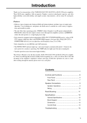
This Owner's Manual covers the three models: KAX-5000, KAX-3500 and KAX-2500 power amplifiers. These KAX-series amplifiers fully incorporate Yamaha's renown technological expertise, and offer high reliability, rock-solid stability, and superb acoustic characteristics-all in a safe place. Contents
Controls and Functions 6 Front Panel 6 Rear ...
Owner's Manual - Page 6
...
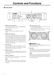
3 PROTECTION indicator Lights up . How to install the security cover (1) Use the supplied hex...power on the rear
panel is set ON. (See page 7.)
8 Air intakes The amplifier uses forced-air cooling.
The... because the signal level is corrected, the indicator goes off . Specifically, lights up if the heat sink overheats, or if a DC...start-up is completed or the problem is too high.
5 SIGNAL ...
Owner's Manual - Page 7
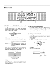
... XLR-3-31 input jacks are wired as to adjust the cutoff frequency.
Note that are lower than the cutoff set to select the filter, as follows. You use this switch ON, the amplifier adds low-frequency
compensation so as shown below. LOW CUT Use a high-pass filter.
The results (the
actual change...
Owner's Manual - Page 8
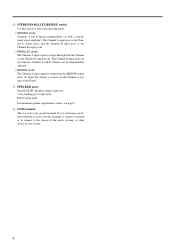
... jacks do not function. To adjust the volume, you are having a problem with hum or noise, use the Channel A volume control knob.
5 ... switch to select the operating mode.
• STEREO mode Channels A and B operate independently (as with a conventional stereo amplifier). Channel A and B volumes can be independently adjusted.
• BRIDGE mode The Channel A input signal is output through...
Owner's Manual - Page 9
...:
8 Ω
Minimum speaker impedance:
4 Ω
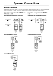
9 Speaker Connections
■ Speaker impedance
Speakers can be sure that speaker impedance will vary according to the amplifier as shown below .
Minimum speaker impedance:
8 Ω
When using Speakon connector
Minimum speaker impedance:
4 Ω
LOCK
LOCK SPEAKERS
3
2
23
+ 1+ - 1-
1+ + 1- -
2+ + 2- -
Minimum speaker impedance...
Owner's Manual - Page 10
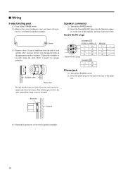
... to securely clamp the wires. Neutrik NL4FC plugs
CHANNEL A
STEREO or PARALLEL BRIDGE
1+
A+
1+
+
1-
B-
2-
Screw
(3) Remove about 15 mm of insulation from the end of the amplifier, and turn clockwise to lock.
tor on the rear of the ampli-
A-
1-
2+
B+
2+
-
2- Neutrik NL4FC plugs
CHANNEL B
1+
B+
1- Tighten the terminals to page 9 for speaker polarities.
*
...
Owner's Manual - Page 11
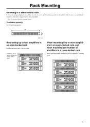
... rack
If you are mounting multiple power amplifiers in a rack, be sure to use metal brackets (one on each side) to install ventilation panel(s) as shown below. Also be sure to support the rear of the rack.)
When mounting five or more amplifiers in an open -backed rack
Install a ventilation panel as shown below.
Note...
Owner's Manual - Page 12
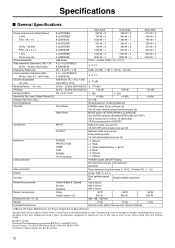
... Power Output Level (Rated Power)
Specifications and descriptions in EN55103-1 and EN55103-2. Specifications
■ General Specifications
Power Output Level (Rated Power) 1 kHz THD + N = 1%
8 Ω/STEREO 4 Ω/STEREO 8 Ω/BRIDGE
KAX-5000 525 W × 2 750 W × 2 1500 W × 1
KAX-3500 390 W × 2 590 W × 2 1180 W × 1
KAX-2500 275 W × 2 390 W × 2 780...
Owner's Manual - Page 14
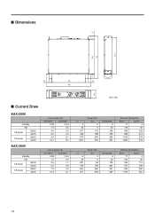
...
standby
idle
1/8 power
8Ω/ch 4Ω/ch
1/3 power
8Ω/ch 4Ω/ch
KAX-3500
standby
idle
1/8 power
8Ω/ch 4Ω/ch
1/3 power
8Ω/ch 4Ω/ch
Line Current (A)
100/120V
230/240V
0.08
0.04
1.0
0.5
4.0
2.2
6.2
3.4
9.3
5.1
14.7
8.1
Line Current (A)
100/...
Owner's Manual - Page 15
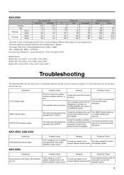
...KAX-2500: 103A (100V), 150A (120V), 68A (240V)
Thermal Dissipation
Btu/h
kcal/h
17
4
85
22
358
90
592
149
811
204
1350
341
Troubleshooting
The following table lists the main causes of ± 2 V or greater was generated in the power amplifier...Yamaha service center. TEMP indicator lights. Check the ventilation slots, and provide better airflow around the amplifier.
KAX-2500...
Yamaha KAX-2500 Reviews
We have not received any reviews for Yamaha yet.