
Owner's Manual
Page 2
... to follow instructions could void your authority, granted by the FCC, to products distributed by YAMAHA CORPORATION OF AMERICA. (FCC DoC) that are on different branch (circuit breaker or fuse) circuits or install AC line filter/s. FCC INFORMATION (U.S.A.) 1. IMPORTANT NOTICE: DO NOT MODIFY THIS UNIT! In the case of Equipment : MIXING CONSOLE Model Name : IM8-40/IM8-32/IM8-24 This...
... to follow instructions could void your authority, granted by the FCC, to products distributed by YAMAHA CORPORATION OF AMERICA. (FCC DoC) that are on different branch (circuit breaker or fuse) circuits or install AC line filter/s. FCC INFORMATION (U.S.A.) 1. IMPORTANT NOTICE: DO NOT MODIFY THIS UNIT! In the case of Equipment : MIXING CONSOLE Model Name : IM8-40/IM8-32/IM8-24 This...
Owner's Manual
Page 3
...plug does not fit into the apparatus, the apparatus has been exposed to avoid injury from the apparatus. 11 Only use this apparatus during lightning storms or when unused for replacement of the obsolete outlet. 10 Protect the power cord from being walked on the rear of time. 14 Refer all servicing to persons. IMPORTANT SAFETY INSTRUCTIONS 1 Read these instructions... dry cloth. 7 Do not block any heat sources such as power-supply cord or plug is used, use caution when moving the cart/apparatus combination to rain or moisture, does not operate normally, or has been dropped....
...plug does not fit into the apparatus, the apparatus has been exposed to avoid injury from the apparatus. 11 Only use this apparatus during lightning storms or when unused for replacement of the obsolete outlet. 10 Protect the power cord from being walked on the rear of time. 14 Refer all servicing to persons. IMPORTANT SAFETY INSTRUCTIONS 1 Read these instructions... dry cloth. 7 Do not block any heat sources such as power-supply cord or plug is used, use caution when moving the cart/apparatus combination to rain or moisture, does not operate normally, or has been dropped....
Owner's Manual
Page 4
... not use the headphones or speakers for all devices, set all volume levels to lift the device by qualified Yamaha service personnel. • Never insert or remove an electric plug with electrical contact or fader motion. • Do not use the device in the vicinity of a TV, radio, stereo equipment, mobile phone, or other devices, turn on or off the power for future...
... not use the headphones or speakers for all devices, set all volume levels to lift the device by qualified Yamaha service personnel. • Never insert or remove an electric plug with electrical contact or fader motion. • Do not use the device in the vicinity of a TV, radio, stereo equipment, mobile phone, or other devices, turn on or off the power for future...
Owner's Manual
Page 5
... relevant laws. Copying of this manual are for instructional purposes only, and may not be held responsible for the results of the use of the commercially available musical data including but not limited to change or modify products of components with moving contacts, such as switches, volume controls, and connectors, deteriorates over time. reserves the right to MIDI data and/or audio data is strictly...
... relevant laws. Copying of this manual are for instructional purposes only, and may not be held responsible for the results of the use of the commercially available musical data including but not limited to change or modify products of components with moving contacts, such as switches, volume controls, and connectors, deteriorates over time. reserves the right to MIDI data and/or audio data is strictly...
Owner's Manual
Page 6
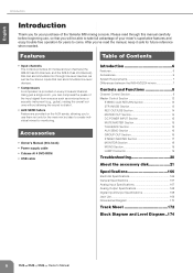
... DC POWER INPUT Section 15 MUTE MASTER Section 15 TALKBACK Section 15 AUX SEND Section 16 GROUP OUT Section 16 STEREO MASTER Section 17 MONITOR Section 18 MONO Section 19 LAMP Connector 19 Troubleshooting 20 About the accessory disk 21 Specifications 166 Electrical Specifications 166 General Specifications 167 Analog Input Specifications 167 Analog Output Specifications 168 Digital Input/Output Specifications 168 Jack List 169 Dimensional Diagram 170 Track Sheet 172 Block Diagram and Level Diagram..174 6 Owner's Manual After you've read through line-level...
... DC POWER INPUT Section 15 MUTE MASTER Section 15 TALKBACK Section 15 AUX SEND Section 16 GROUP OUT Section 16 STEREO MASTER Section 17 MONITOR Section 18 MONO Section 19 LAMP Connector 19 Troubleshooting 20 About the accessory disk 21 Specifications 166 Electrical Specifications 166 General Specifications 167 Analog Input Specifications 167 Analog Output Specifications 168 Digital Input/Output Specifications 168 Jack List 169 Dimensional Diagram 170 Track Sheet 172 Block Diagram and Level Diagram..174 6 Owner's Manual After you've read through line-level...
Owner's Manual
Page 8
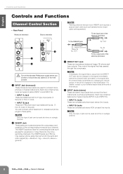
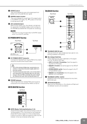
... for connecting devices such as illustrated below (insert cable sold separately). They output the signal that is output from the console. 1 INPUT Jack (monaural) These monaural input jacks are located between the compressor and equalizer of the external processor To the INSERT jack Tip: OUT 1 4 2 3 Turn off the Yamaha PW8 power supply before the channel fader (pre-fader) or the signal after the channel fader (post-fader) by changing an internal jumper. To the input jack of the corresponding monaural input channel. ring...
... for connecting devices such as illustrated below (insert cable sold separately). They output the signal that is output from the console. 1 INPUT Jack (monaural) These monaural input jacks are located between the compressor and equalizer of the external processor To the INSERT jack Tip: OUT 1 4 2 3 Turn off the Yamaha PW8 power supply before the channel fader (pre-fader) or the signal after the channel fader (post-fader) by changing an internal jumper. To the input jack of the corresponding monaural input channel. ring...

Owner's Manual
Page 9
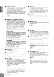
... mix a phasereversed signal. all the way down. Turn this switch ON will interfere with a low input level to the INPUT A jack of 12 dB/ octave. • Top Panel Monaural channels Stereo channels 5 6 7 8 9 0 A B C D E F G H I J K L Controls and Functions 5 +48V Switch/Indicator This switch toggles phantom power on and off ( ) if you've connected a microphone or other device with each other, resulting in degraded sound quality. 9 (High Pass Filter) Switch This switch toggles the HPF on or off. The adjustable...
... mix a phasereversed signal. all the way down. Turn this switch ON will interfere with a low input level to the INPUT A jack of 12 dB/ octave. • Top Panel Monaural channels Stereo channels 5 6 7 8 9 0 A B C D E F G H I J K L Controls and Functions 5 +48V Switch/Indicator This switch toggles phantom power on and off ( ) if you've connected a microphone or other device with each other, resulting in degraded sound quality. 9 (High Pass Filter) Switch This switch toggles the HPF on or off. The adjustable...
Owner's Manual
Page 10
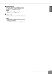
... pre-fader signal is sent to the AUX buses can turn on the channel ON switch (G). For details, contact to AUX buses 1-8. Controls and Functions English 0 COMP Control/Indicator Adjusts the amount of compression applied to the "▼" position produces a flat response in the MUTE MASTER section, the input channels whose corresponding MUTE switch is on will light red when the input signal reaches 3 dB before the equalizer by the PRE switch (D). Setting the gain control...
... pre-fader signal is sent to the AUX buses can turn on the channel ON switch (G). For details, contact to AUX buses 1-8. Controls and Functions English 0 COMP Control/Indicator Adjusts the amount of compression applied to the "▼" position produces a flat response in the MUTE MASTER section, the input channels whose corresponding MUTE switch is on will light red when the input signal reaches 3 dB before the equalizer by the PRE switch (D). Setting the gain control...
Owner's Manual
Page 11
Use these faders to the PHONES and MONITOR OUT jacks for monitoring. Controls and Functions Owner's Manual 11 NOTE · To minimize noise, the faders of unused channels should be set to the lowest position. · The channel faders will light. NOTE · When you turn on , the indicator will light and the channel pre-fader signal is off) buses. L Channel Fader Adjusts the output level of the input channel signal. English K PFL Switch/Indicator When the PFL switch is on the PFL switch, the...
Use these faders to the PHONES and MONITOR OUT jacks for monitoring. Controls and Functions Owner's Manual 11 NOTE · To minimize noise, the faders of unused channels should be set to the lowest position. · The channel faders will light. NOTE · When you turn on , the indicator will light and the channel pre-fader signal is off) buses. L Channel Fader Adjusts the output level of the input channel signal. English K PFL Switch/Indicator When the PFL switch is on the PFL switch, the...

Owner's Manual
Page 13
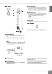
... AUX controls and RETURN control in the MONITOR section (page 18) will light. 2TR IN/USB Section Rear Panel Front Panel 1 4 5 1 AUX RETURN Jacks These are unbalanced phone-jack type line inputs. The signal input from this connector is nominal level (0 dB). Signals input from an external effect device (reverb, delay, etc.). Use these jacks can also be sent to input and output the signals. These jacks are typically used as the REC OUT jacks. When connecting or disconnecting the USB cable be mixed. 2 USB Connector Connects...
... AUX controls and RETURN control in the MONITOR section (page 18) will light. 2TR IN/USB Section Rear Panel Front Panel 1 4 5 1 AUX RETURN Jacks These are unbalanced phone-jack type line inputs. The signal input from this connector is nominal level (0 dB). Signals input from an external effect device (reverb, delay, etc.). Use these jacks can also be sent to input and output the signals. These jacks are typically used as the REC OUT jacks. When connecting or disconnecting the USB cable be mixed. 2 USB Connector Connects...
Owner's Manual
Page 14
... software on the PFL switch, the PFL indicator of the MONITOR section (page 18) will light. 4 REC OUT/USB Section Rear Panel Top Panel 5 1 2 1 REC OUT Jacks These RCA pin jacks can be output. NOTE · If both the ST switch and the MONO switch are on the signal via these operations: (1) when turning the power of less than about 3 meters. • To prevent loud pops and noises, turn on the power...
... software on the PFL switch, the PFL indicator of the MONITOR section (page 18) will light. 4 REC OUT/USB Section Rear Panel Top Panel 5 1 2 1 REC OUT Jacks These RCA pin jacks can be output. NOTE · If both the ST switch and the MONO switch are on the signal via these operations: (1) when turning the power of less than about 3 meters. • To prevent loud pops and noises, turn on the power...
Owner's Manual
Page 15
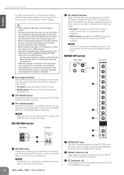
... master control is output to or from the console. • To prevent loud pops and noises, turn off . English Controls and Functions 4 MONO Control This control adjusts the level of the signal sent from MONO OUT to the MATRIX OUT jacks. 5 MATRIX master Control This control adjusts the overall level of the signal output to the console and the PW8 is turned on and off all PFL switches. MUTE MASTER Section Top Panel TALKBACK Section Rear Panel Top Panel 1 2 3 4 1 TALKBACK MIC IN Jack This is connected...
... master control is output to or from the console. • To prevent loud pops and noises, turn off . English Controls and Functions 4 MONO Control This control adjusts the level of the signal sent from MONO OUT to the MATRIX OUT jacks. 5 MATRIX master Control This control adjusts the overall level of the signal output to the console and the PW8 is turned on and off all PFL switches. MUTE MASTER Section Top Panel TALKBACK Section Rear Panel Top Panel 1 2 3 4 1 TALKBACK MIC IN Jack This is connected...

Owner's Manual
Page 16
... the input jack of the external processor 4 AUX SEND Fader Controls the level of the signal output to the AUX SEND jack. 5 AFL Switch/Indicator When the AFL switch is on, the indicator will light and the signal after the AUX SEND fader is output to the MONITOR OUT and PHONES jacks for example, to connect to monitor the signal after the AUX SEND fader. NOTE · If you want to a monitor system or an external effect unit. 3 AUX SEND Meter Three LEDs indicate the signal level...
... the input jack of the external processor 4 AUX SEND Fader Controls the level of the signal output to the AUX SEND jack. 5 AFL Switch/Indicator When the AFL switch is on, the indicator will light and the signal after the AUX SEND fader is output to the MONITOR OUT and PHONES jacks for example, to connect to monitor the signal after the AUX SEND fader. NOTE · If you want to a monitor system or an external effect unit. 3 AUX SEND Meter Three LEDs indicate the signal level...

Owner's Manual
Page 17
... monitor the signal after the GROUP OUT fader, turn off all PFL switches. 8 GROUP OUT Fader Controls the level of the signals sent from GROUP OUT to the ST L/R bus. sleeve = ground). You can connect a graphic equalizer or other such device. 3 PAN Controls These adjust the stereo position of the GROUP OUT signal. STEREO MASTER Section Rear Panel 1 2 3 4 5 6 7 Controls and Functions Top Panel 1 STEREO INSERT Jack This is a TRS (tip, ring, sleeve) phone jack that carries both the send and return signal...
... monitor the signal after the GROUP OUT fader, turn off all PFL switches. 8 GROUP OUT Fader Controls the level of the signals sent from GROUP OUT to the ST L/R bus. sleeve = ground). You can connect a graphic equalizer or other such device. 3 PAN Controls These adjust the stereo position of the GROUP OUT signal. STEREO MASTER Section Rear Panel 1 2 3 4 5 6 7 Controls and Functions Top Panel 1 STEREO INSERT Jack This is a TRS (tip, ring, sleeve) phone jack that carries both the send and return signal...
Owner's Manual
Page 18
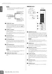
... output jacks that you can connect to your main speakers. 3 STEREO Level Meter These LEDs indicate the level of headphones to the power amplifiers that output the mixed stereo signal. The "0" segment indicates the nominal output level. The PFL indicator will light when the signals before or after the faders for the various buses. NOTE · If you want to monitor the signal after the STEREO OUT master faders, turn off all PFL switches. 2 PHONES Jack Connects...
... output jacks that you can connect to your main speakers. 3 STEREO Level Meter These LEDs indicate the level of headphones to the power amplifiers that output the mixed stereo signal. The "0" segment indicates the nominal output level. The PFL indicator will light when the signals before or after the faders for the various buses. NOTE · If you want to monitor the signal after the STEREO OUT master faders, turn off all PFL switches. 2 PHONES Jack Connects...
Owner's Manual
Page 19
... Rear Panel 1 2 3 Top Panel 4 Controls and Functions 4 MONO Level Meter Three LEDs indicate the signal level after the MONO fader is a TRS (tip, ring, sleeve) phone jack that supplies power to the MONO jack. Owner's Manual 19 This is output to the MONITOR OUT and PHONES jacks for monitoring. To the input jack of these connectors, and the IM8-32/24 mixers have the same output impedance, these output jacks are less affected by induced noise. The IM8-40 mixer has three of the external...
... Rear Panel 1 2 3 Top Panel 4 Controls and Functions 4 MONO Level Meter Three LEDs indicate the signal level after the MONO fader is a TRS (tip, ring, sleeve) phone jack that supplies power to the MONO jack. Owner's Manual 19 This is output to the MONITOR OUT and PHONES jacks for monitoring. To the input jack of these connectors, and the IM8-32/24 mixers have the same output impedance, these output jacks are less affected by induced noise. The IM8-40 mixer has three of the external...
Owner's Manual
Page 20
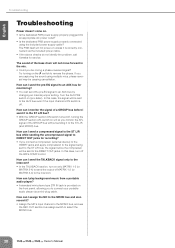
... problem, call Yamaha for monitoring? • You can I play background music from a portable audio player? • A standard mini-phone type 2TR IN jack is off the IM8's COMP control. English Troubleshooting Troubleshooting Power doesn't come on the front panel, allowing you be sent to the DIRECT OUT jacks. The sound of the GROUP bus without sending it ? • Assign the MC's input channel to the MONO bus, and use the REC OUT section bus assign switch to select the MONO bus. 20 Owner's Manual...
... problem, call Yamaha for monitoring? • You can I play background music from a portable audio player? • A standard mini-phone type 2TR IN jack is off the IM8's COMP control. English Troubleshooting Troubleshooting Power doesn't come on the front panel, allowing you be sent to the DIRECT OUT jacks. The sound of the GROUP bus without sending it ? • Assign the MC's input channel to the MONO bus, and use the REC OUT section bus assign switch to select the MONO bus. 20 Owner's Manual...
Owner's Manual
Page 22
... SOFTWARE in whole or in part, or create derivative works of the SOFTWARE. · You may not initiate services based on the day that use of the copyright owner. 3. GRANT OF LICENSE AND COPYRIGHT Yamaha hereby grants you receive the SOFTWARE and remains effective until terminated. While you must immediately destroy the licensed SOFTWARE, any accompanying written materials and supersedes all copies...
... SOFTWARE in whole or in part, or create derivative works of the SOFTWARE. · You may not initiate services based on the day that use of the copyright owner. 3. GRANT OF LICENSE AND COPYRIGHT Yamaha hereby grants you receive the SOFTWARE and remains effective until terminated. While you must immediately destroy the licensed SOFTWARE, any accompanying written materials and supersedes all copies...
Owner's Manual
Page 25
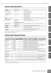
....) Italiano Owner's Manual 167 English Español Français Deutsch Specifications General Specifications Input HPF Input Equalization (+15, -15dB maximum) Turn over/roll-off frequency of XLR-4-31 connectors. LAMP IM8-40: 3 pcs, IM8-32/24: 2pcs Signal Indicator LED Level Meter USB Audio Compressor Dimensions Net Weight MONO CH INPUT* MONO CH INPUT* ST CH INPUT MONO CH INPUT* ST CH INPUT 1-4 INSERT OUT GROUP OUT, AUX SEND, MONO OUT Post STEREO OUT fader Pre MONITOR control USB IN/OUT MONO CH INPUT...
....) Italiano Owner's Manual 167 English Español Français Deutsch Specifications General Specifications Input HPF Input Equalization (+15, -15dB maximum) Turn over/roll-off frequency of XLR-4-31 connectors. LAMP IM8-40: 3 pcs, IM8-32/24: 2pcs Signal Indicator LED Level Meter USB Audio Compressor Dimensions Net Weight MONO CH INPUT* MONO CH INPUT* ST CH INPUT MONO CH INPUT* ST CH INPUT 1-4 INSERT OUT GROUP OUT, AUX SEND, MONO OUT Post STEREO OUT fader Pre MONITOR control USB IN/OUT MONO CH INPUT...
Owner's Manual
Page 32
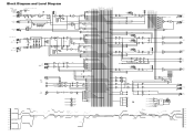
...] [-7.8dBu] R AUX SEND 1-8 [+4dBu] L MONITOR OUT [+4dBu] R PHONES [3mW 40ohms] CTRL MUTEMASTER 1 RED 2 RED 3 RED 4 RED POWER GR Clip Level(GROUP) BUS(GROUP, ST, MONO, PFL, AFL) GROUP INSERT I/O [0dBu] BUS(AUX) AUX INV GROUP Fader [Nominal:-10dB] GROUP OUT [+4dBu] ST, MONO, AUX INSERT I/O [0dBu] ST, MONO, AUX Fader [Nominal:-10dB] USB OUT(L) USB OUT(R) LPF [0dBu] LPF USB IN(L) USB IN(R) LPF [0dBu] LPF LIN USB D- RIN AUDIO D+ LO GND RO ( Bus Powered) Vbus USB Clip Level (ST, MONO, AUX) Clip Level (REC OUT...
...] [-7.8dBu] R AUX SEND 1-8 [+4dBu] L MONITOR OUT [+4dBu] R PHONES [3mW 40ohms] CTRL MUTEMASTER 1 RED 2 RED 3 RED 4 RED POWER GR Clip Level(GROUP) BUS(GROUP, ST, MONO, PFL, AFL) GROUP INSERT I/O [0dBu] BUS(AUX) AUX INV GROUP Fader [Nominal:-10dB] GROUP OUT [+4dBu] ST, MONO, AUX INSERT I/O [0dBu] ST, MONO, AUX Fader [Nominal:-10dB] USB OUT(L) USB OUT(R) LPF [0dBu] LPF USB IN(L) USB IN(R) LPF [0dBu] LPF LIN USB D- RIN AUDIO D+ LO GND RO ( Bus Powered) Vbus USB Clip Level (ST, MONO, AUX) Clip Level (REC OUT...


