
Owner's Manual
Page 1
U HTR-6130 AV Receiver OWNER'S MANUAL
U HTR-6130 AV Receiver OWNER'S MANUAL

Owner's Manual
Page 2
Do not use this product on the marking label. and the like. 8 Accessories - This product may be moved with care. This is damaged, b) If liquid has been spilled, or objects have been adhered to persons. If you are provided for ventilation and to ensure reliable operation of time, unplug it can result in a fire or electric shock. When installing an outside antenna system should be equipped with the product. Do not attempt to qualified service personnel under the following conditions: a) When the power-supply cord or plug is a safety feature. Unplug this ...
Do not use this product on the marking label. and the like. 8 Accessories - This product may be moved with care. This is damaged, b) If liquid has been spilled, or objects have been adhered to persons. If you are provided for ventilation and to ensure reliable operation of time, unplug it can result in a fire or electric shock. When installing an outside antenna system should be equipped with the product. Do not attempt to qualified service personnel under the following conditions: a) When the power-supply cord or plug is a safety feature. Unplug this ...

Owner's Manual
Page 3
... completion of other electronic devices. EXAMPLE OF ANTENNA GROUNDING MAST GROUND CLAMP ELECTRIC SERVICE EQUIPMENT NEC - Modifications not expressly approved by Yamaha may cause interference harmful to the operation of any way, and f) When the product exhibits a distinct change the lead-in ... Mounting - This product, when installed as close to the point of interference, which can not locate the appropriate retailer, please contact Yamaha Electronics Corp., U.S.A. 6660 Orangethorpe Ave., Buena Park, CA 90620. If an outside antenna or cable system is in fire, electric ...
... completion of other electronic devices. EXAMPLE OF ANTENNA GROUNDING MAST GROUND CLAMP ELECTRIC SERVICE EQUIPMENT NEC - Modifications not expressly approved by Yamaha may cause interference harmful to the operation of any way, and f) When the product exhibits a distinct change the lead-in ... Mounting - This product, when installed as close to the point of interference, which can not locate the appropriate retailer, please contact Yamaha Electronics Corp., U.S.A. 6660 Orangethorpe Ave., Buena Park, CA 90620. If an outside antenna or cable system is in fire, electric ...

Owner's Manual
Page 4
...or personal injury. Keep it may overheat, possibly causing damage. 9 Do not use of the unit. this unit with Canadian ICES-003. Contact qualified Yamaha service personnel when any damage resulting from use force on common operating errors before operating your local main voltage BEFORE plugging into the AC wall...chocs électriques, introduire la lame la plus large de la fiche dans la borne correspondante de la prise et pousser jusqu'au fond. Yamaha will not be opened for future reference. WARNING TO REDUCE THE RISK OF FIRE OR ELECTRIC SHOCK, DO NOT EXPOSE THIS UNIT TO RAIN ...
...or personal injury. Keep it may overheat, possibly causing damage. 9 Do not use of the unit. this unit with Canadian ICES-003. Contact qualified Yamaha service personnel when any damage resulting from use force on common operating errors before operating your local main voltage BEFORE plugging into the AC wall...chocs électriques, introduire la lame la plus large de la fiche dans la borne correspondante de la prise et pousser jusqu'au fond. Yamaha will not be opened for future reference. WARNING TO REDUCE THE RISK OF FIRE OR ELECTRIC SHOCK, DO NOT EXPOSE THIS UNIT TO RAIN ...

Owner's Manual
Page 5
... (U.S.A. and Canada models only 12 Information on jacks and cable plugs 13 Information on HDMI 14 Connecting video components 15 Connecting audio components 17 Connecting a Yamaha iPod™ universal dock and Bluetooth™ adapter 18 Connecting to the VIDEO AUX jacks on the front panel 18 Connecting the FM and AM...
... (U.S.A. and Canada models only 12 Information on jacks and cable plugs 13 Information on HDMI 14 Connecting video components 15 Connecting audio components 17 Connecting a Yamaha iPod™ universal dock and Bluetooth™ adapter 18 Connecting to the VIDEO AUX jacks on the front panel 18 Connecting the FM and AM...

Owner's Manual
Page 6
...license agreement. "SILENT CINEMA" is a trademark of Apple Inc., registered in the U.S. We Want You Listening For A Lifetime Yamaha and the Electronic Industries Association's Consumer Electronics Group want you to avoid prolonged exposure from excessive volume levels. 2 En iPod™... ◆ Preset SCENE templates for various situations ◆ SCENE template customizing capability Decoders and DSP circuits ◆ Proprietary Yamaha technology for standard, enhanced or high-definition video (includes 1080p video signal transmission) DOCK terminal ◆ DOCK terminal to...
...license agreement. "SILENT CINEMA" is a trademark of Apple Inc., registered in the U.S. We Want You Listening For A Lifetime Yamaha and the Electronic Industries Association's Consumer Electronics Group want you to avoid prolonged exposure from excessive volume levels. 2 En iPod™... ◆ Preset SCENE templates for various situations ◆ SCENE template customizing capability Decoders and DSP circuits ◆ Proprietary Yamaha technology for standard, enhanced or high-definition video (includes 1080p video signal transmission) DOCK terminal ◆ DOCK terminal to...

Owner's Manual
Page 7
Voltages are 110-120/220-240 V AC, 50/60 Hz. the operation range of the remote control decreases. • Do not use an old battery and a new one together. • Do not use different types of the battery compartment. 3 Snap the battery compartment cover back into place. dispose of them immediately. Select the switch position (upper or lower) according to your local voltage BEFORE plugging the power cable into contact with your local regulations. • If the remote control is cleared, insert new batteries and set for more than 2 minutes, or if exhausted batteries remain in ...
Voltages are 110-120/220-240 V AC, 50/60 Hz. the operation range of the remote control decreases. • Do not use an old battery and a new one together. • Do not use different types of the battery compartment. 3 Snap the battery compartment cover back into place. dispose of them immediately. Select the switch position (upper or lower) according to your local voltage BEFORE plugging the power cable into contact with your local regulations. • If the remote control is cleared, insert new batteries and set for more than 2 minutes, or if exhausted batteries remain in ...
Owner's Manual
Page 8
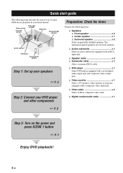
The minimum required speakers are two front speakers. ❏ Active subwoofer x 1 Select an active subwoofer equipped with an RCA input jack. ❏ Speaker cable x 5 ❏ Subwoofer cable x 1 Select a monaural RCA cable. ❏ DVD player x 1 Select DVD player equipped with coaxial digital audio output jack and composite video output jack. ❏ Video monitor x 1 Select a TV monitor, video monitor or projector equipped with a composite video input jack. ❏ Video cable x 2 Select an RCA composite video cable. ❏ Digital coaxial audio cable x 1 ☞ P. 6 Step...
The minimum required speakers are two front speakers. ❏ Active subwoofer x 1 Select an active subwoofer equipped with an RCA input jack. ❏ Speaker cable x 5 ❏ Subwoofer cable x 1 Select a monaural RCA cable. ❏ DVD player x 1 Select DVD player equipped with coaxial digital audio output jack and composite video output jack. ❏ Video monitor x 1 Select a TV monitor, video monitor or projector equipped with a composite video input jack. ❏ Video cable x 2 Select an RCA composite video cable. ❏ Digital coaxial audio cable x 1 ☞ P. 6 Step...

Owner's Manual
Page 9
Quick start guide Be sure to connect the left speaker Center and surround speakers Press down Insert Release Cables are unplugged from the AC wall outlets. 2 Twist the exposed wires of the speaker cables together to prevent short circuits. 3 Do not let the bare speaker wires touch each other. 4 Do not let the bare speaker wires touch any metal part of your speaker. Subwoofer AV receiver Input jack Subwoofer cable SUBWOOFER OUTPUT jack English 5 En To the surround right speaker To the center speaker To the surround left speaker 1 2 3 4 1 Make sure that this unit. DOCK...
Quick start guide Be sure to connect the left speaker Center and surround speakers Press down Insert Release Cables are unplugged from the AC wall outlets. 2 Twist the exposed wires of the speaker cables together to prevent short circuits. 3 Do not let the bare speaker wires touch each other. 4 Do not let the bare speaker wires touch any metal part of your speaker. Subwoofer AV receiver Input jack Subwoofer cable SUBWOOFER OUTPUT jack English 5 En To the surround right speaker To the center speaker To the surround left speaker 1 2 3 4 1 Make sure that this unit. DOCK...

Owner's Manual
Page 10
Video monitor AV receiver Make sure that this unit and the DVD player are unplugged from the AC wall outlets. 1 Connect the digital coaxial audio cable to the digital coaxial audio output jack on your DVD player and the DVD VIDEO jack on this unit. Quick start guide Step 2: Connect your video monitor and the VIDEO MONITOR OUT jack on this unit. DVD player AV receiver • Using the VIDEO AUX jacks on this unit and other components into the AC wall outlet. ■ For further connections • Using the other kind of speaker combinations ☞ P. 10 • Connecting a ...
Video monitor AV receiver Make sure that this unit and the DVD player are unplugged from the AC wall outlets. 1 Connect the digital coaxial audio cable to the digital coaxial audio output jack on your DVD player and the DVD VIDEO jack on this unit. Quick start guide Step 2: Connect your video monitor and the VIDEO MONITOR OUT jack on this unit. DVD player AV receiver • Using the VIDEO AUX jacks on this unit and other components into the AC wall outlet. ■ For further connections • Using the other kind of speaker combinations ☞ P. 10 • Connecting a ...

Owner's Manual
Page 11
... of the SCENE control signals, this room. Radio Listening *2, *3, *4 - If the speakers are built combinations of input sources and sound field programs. y If you connect a Yamaha product that has been assigned to a music disc from the FM radio station English 7 En to a music disc from the connected DVD player as the...
... of the SCENE control signals, this room. Radio Listening *2, *3, *4 - If the speakers are built combinations of input sources and sound field programs. y If you connect a Yamaha product that has been assigned to a music disc from the FM radio station English 7 En to a music disc from the connected DVD player as the...

Owner's Manual
Page 12
See page 16 for details. *2 To use the "Radio Listening" template (Case C), you have to the standby mode. To turn on this unit from the remote control. ■ Adjusting the parameters of this unit • Optimizing the speaker parameters for the tuning information. *4 To achieve the best possible reception, orient the connected AM loop antenna, or adjust the position of the end of this unit ☞ P. 33 8 En Note In the standby mode, this unit consumes a small amount of this unit ☞ P. 43 • Setting the remote control ☞ P. 51 • Adjusting the advanced...
See page 16 for details. *2 To use the "Radio Listening" template (Case C), you have to the standby mode. To turn on this unit from the remote control. ■ Adjusting the parameters of this unit • Optimizing the speaker parameters for the tuning information. *4 To achieve the best possible reception, orient the connected AM loop antenna, or adjust the position of the end of this unit ☞ P. 33 8 En Note In the standby mode, this unit consumes a small amount of this unit ☞ P. 43 • Setting the remote control ☞ P. 51 • Adjusting the advanced...

Owner's Manual
Page 13
IN MD/ OUT (PLAY) CD-R (REC) OUTPUT SUB WOOFER R FRONT A L Connections 7 8 9 0 Name 1 DOCK terminal 2 COMPONENT VIDEO jacks 3 HDMI jacks 4 VIDEO jacks 5 ANTENNA terminals 6 SPEAKERS terminals 7 DIGITAL INPUT jacks 8 MULTI CH INPUT jacks 9 AUDIO jacks 0 SUBWOOFER OUTPUT jack See page 18 16 16 15 19 11 15, 17 17 15, 17 11 English 9 En PREPARATION Rear panel 1 2 Connections 3 45 6 DOCK COMPONENT VIDEO DVD DTV/CBL DVR MONITOR OUT PR OUT DVD DTV/CBL HDMI DIGITAL INPUT PB OPTICAL Y CD 3 DTV/ CBL 2 MULTI CH INPUT FRONT SURROUND CENTER L DVD VIDEO DTV/CBL DVR IN ...
IN MD/ OUT (PLAY) CD-R (REC) OUTPUT SUB WOOFER R FRONT A L Connections 7 8 9 0 Name 1 DOCK terminal 2 COMPONENT VIDEO jacks 3 HDMI jacks 4 VIDEO jacks 5 ANTENNA terminals 6 SPEAKERS terminals 7 DIGITAL INPUT jacks 8 MULTI CH INPUT jacks 9 AUDIO jacks 0 SUBWOOFER OUTPUT jack See page 18 16 16 15 19 11 15, 17 17 15, 17 11 English 9 En PREPARATION Rear panel 1 2 Connections 3 45 6 DOCK COMPONENT VIDEO DVD DTV/CBL DVR MONITOR OUT PR OUT DVD DTV/CBL HDMI DIGITAL INPUT PB OPTICAL Y CD 3 DTV/ CBL 2 MULTI CH INPUT FRONT SURROUND CENTER L DVD VIDEO DTV/CBL DVR IN ...
Owner's Manual
Page 14
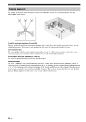
... low bass sounds are used for effect and surround sounds. The position of the LFE (low-frequency effect) channel included in amplifier, such as the Yamaha Active Servo Processing Subwoofer System, is effective not only for reinforcing bass frequencies from the ideal listening position. Surround left and right speakers (FL and...
... low bass sounds are used for effect and surround sounds. The position of the LFE (low-frequency effect) channel included in amplifier, such as the Yamaha Active Servo Processing Subwoofer System, is effective not only for reinforcing bass frequencies from the ideal listening position. Surround left and right speakers (FL and...

Owner's Manual
Page 15
to the SPEAKERS terminal A speaker cord is disconnected from the AC wall outlet. • Do not let the bare speaker wires touch each speaker cable and then twist the bare wires of this unit and/or speakers. • Use magnetically shielded speakers. Surround speakers Right Left Center speaker Front speakers (B) Right Left DOCK COMPONENT VIDEO DVD DTV/CBL DVR MONITOR OUT PR OUT DVD DTV/CBL HDMI DIGITAL INPUT PB OPTICAL Y CD 3 DTV/ CBL 2 COAXIAL DVD 1 DVD VIDEO DTV/CBL DVR IN OUT MONITOR OUT MULTI CH INPUT FRONT SURROUND CENTER L DVD DTV/CBL AUDIO DVR CD IN...
to the SPEAKERS terminal A speaker cord is disconnected from the AC wall outlet. • Do not let the bare speaker wires touch each speaker cable and then twist the bare wires of this unit and/or speakers. • Use magnetically shielded speakers. Surround speakers Right Left Center speaker Front speakers (B) Right Left DOCK COMPONENT VIDEO DVD DTV/CBL DVR MONITOR OUT PR OUT DVD DTV/CBL HDMI DIGITAL INPUT PB OPTICAL Y CD 3 DTV/ CBL 2 COAXIAL DVD 1 DVD VIDEO DTV/CBL DVR IN OUT MONITOR OUT MULTI CH INPUT FRONT SURROUND CENTER L DVD DTV/CBL AUDIO DVR CD IN...

Owner's Manual
Page 16
First, tighten the knob and then insert the banana plug connector into the slit on the terminal. 3 Tighten the knob to turn on or off . This unit turns on the terminal. 3 Release the tab to the standby mode. The following display appears in the front panel display. Banana plug SP IMP.- 8 MIN ■ Connecting to the FRONT B, CENTER, and SURROUND terminals 4 Press LSTRAIGHT repeatedly to select "SP IMP.". SP IMP.- 6 MIN 5 Press ASTANDBY/ON to confirm your selection and set "SP IMP." Note The setting you made is a single-pole electrical connector widely used to use 6 ohm...
First, tighten the knob and then insert the banana plug connector into the slit on the terminal. 3 Tighten the knob to turn on or off . This unit turns on the terminal. 3 Release the tab to the standby mode. The following display appears in the front panel display. Banana plug SP IMP.- 8 MIN ■ Connecting to the FRONT B, CENTER, and SURROUND terminals 4 Press LSTRAIGHT repeatedly to select "SP IMP.". SP IMP.- 6 MIN 5 Press ASTANDBY/ON to confirm your selection and set "SP IMP." Note The setting you made is a single-pole electrical connector widely used to use 6 ohm...

Owner's Manual
Page 17
Notes • You can use the digital jacks to input PCM, Dolby Digital and DTS bitstreams. All digital input jacks are not output at the digital jacks are compatible with digital signals with up to the left and right analog audio cables. PREPARATION Information on jacks and cable plugs Audio jacks and cable plugs AUDIO L R DIGITAL AUDIO COAXIAL DIGITAL AUDIO OPTICAL Connections Video jacks and cable plugs VIDEO COMPONENT VIDEO Y PB PR (White) (Red) (Orange) (Yellow) (Green) (Blue) (Red) L R C O V Y PB PR Left and right analog audio cable plugs Coaxial ...
Notes • You can use the digital jacks to input PCM, Dolby Digital and DTS bitstreams. All digital input jacks are not output at the digital jacks are compatible with digital signals with up to the left and right analog audio cables. PREPARATION Information on jacks and cable plugs Audio jacks and cable plugs AUDIO L R DIGITAL AUDIO COAXIAL DIGITAL AUDIO OPTICAL Connections Video jacks and cable plugs VIDEO COMPONENT VIDEO Y PB PR (White) (Red) (Orange) (Yellow) (Green) (Blue) (Red) L R C O V Y PB PR Left and right analog audio cable plugs Coaxial ...

Owner's Manual
Page 18
You can play back pictures by connecting your video monitor and video source component to this unit, - mute the volume of the connected video monitor. make an analog or digital connection besides the HDMI connection (see page 16). - At that time, audio/video signals output from the connected video monitor. Furthermore, available audio/video signals depend on it. • Use a conversion cable (HDMI jack ↔ DVI-D jack) to connect this unit to other DVI components. 14 En Refer to the instruction manual of each connected component. ■ HDMI jack and cable plug HDMI HDMI cable ...
You can play back pictures by connecting your video monitor and video source component to this unit, - mute the volume of the connected video monitor. make an analog or digital connection besides the HDMI connection (see page 16). - At that time, audio/video signals output from the connected video monitor. Furthermore, available audio/video signals depend on it. • Use a conversion cable (HDMI jack ↔ DVI-D jack) to connect this unit to other DVI components. 14 En Refer to the instruction manual of each connected component. ■ HDMI jack and cable plug HDMI HDMI cable ...

Owner's Manual
Page 19
Cable TV or Satellite tuner DVD recorder indicates recommended connections indicates alternative connections English 15 En PREPARATION Connecting video components y You can also connect a video monitor, DVD player, digital TV, and cable TV to this unit. Connections Make sure that this unit and other components are unplugged from the AC wall outlets. ■ Connecting a video monitor and a DVD player ■ Connecting a cable TV/satellite tuner and a DVD recorder DOCK COMPONENT VIDEO DVD DTV/CBL DVR MONITOR OUT PR OUT DVD DTV/CBL HDMI DIGITAL INPUT PB OPTICAL Y CD 3 DTV/ ...
Cable TV or Satellite tuner DVD recorder indicates recommended connections indicates alternative connections English 15 En PREPARATION Connecting video components y You can also connect a video monitor, DVD player, digital TV, and cable TV to this unit. Connections Make sure that this unit and other components are unplugged from the AC wall outlets. ■ Connecting a video monitor and a DVD player ■ Connecting a cable TV/satellite tuner and a DVD recorder DOCK COMPONENT VIDEO DVD DTV/CBL DVR MONITOR OUT PR OUT DVD DTV/CBL HDMI DIGITAL INPUT PB OPTICAL Y CD 3 DTV/ ...

Owner's Manual
Page 20
For example, if you connect your video monitor to this unit. HDMI connection Connecting to the COMPONENT VIDEO jacks Audio signals input at the HDMI jack are output to the connected video monitor only when this unit is turned on and set to the input source (DVD or DTV/CBL). • Available audio/video signals depend on the specification of the connected video monitor. Note Be sure to connect your video components in Video out Video monitor Y PB PR OMPONENT VIDEO DTV/CBL DVR MONITOR OUT OUT DVD DTV/CBL HDMI DVD VIDEO DTV/CBL DVR IN OUT MONITOR OUT ANTENNA AM GND FM 75 ...
For example, if you connect your video monitor to this unit. HDMI connection Connecting to the COMPONENT VIDEO jacks Audio signals input at the HDMI jack are output to the connected video monitor only when this unit is turned on and set to the input source (DVD or DTV/CBL). • Available audio/video signals depend on the specification of the connected video monitor. Note Be sure to connect your video components in Video out Video monitor Y PB PR OMPONENT VIDEO DTV/CBL DVR MONITOR OUT OUT DVD DTV/CBL HDMI DVD VIDEO DTV/CBL DVR IN OUT MONITOR OUT ANTENNA AM GND FM 75 ...