
Owners Manual
Page 2
...removing covers may be moved with them , paying particular attention to overturn. 10 Ventilation - Refer all servicing to ensure reliable operation of power source indicated on an unstable cart, stand, tripod, bracket, or table. Unplug this product on the marking label. Do not use...intended to alert you to the presence of the product should follow the manufacturer's instructions, and should be taken to lightning and power-line surges. 15 Power Lines - for ventilation and to qualified service personnel. 19 Damage Requiring Service - and the like. 8 Accessories - The product...
...removing covers may be moved with them , paying particular attention to overturn. 10 Ventilation - Refer all servicing to ensure reliable operation of power source indicated on an unstable cart, stand, tripod, bracket, or table. Unplug this product on the marking label. Do not use...intended to alert you to the presence of the product should follow the manufacturer's instructions, and should be taken to lightning and power-line surges. 15 Power Lines - for ventilation and to qualified service personnel. 19 Damage Requiring Service - and the like. 8 Accessories - The product...
Owners Manual
Page 3
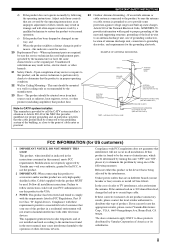
... CODE ANTENNA LEAD IN WIRE ANTENNA DISCHARGE UNIT (NEC SECTION 810-20) GROUNDING CONDUCTORS (NEC SECTION 810-21) GROUND CLAMPS POWER SERVICE GROUNDING ELECTRODE SYSTEM (NEC ART 250. Failure to follow instructions could void your FCC authorization to the operation of cable ... above statements apply ONLY to those controls that your authority, granted by the manufacturer. 23 Heat - Modifications not expressly approved by Yamaha Corporation of radio or TV interference, relocate/reorient the antenna. Compliance with other products (including amplifiers) that are covered by a ...
... CODE ANTENNA LEAD IN WIRE ANTENNA DISCHARGE UNIT (NEC SECTION 810-20) GROUNDING CONDUCTORS (NEC SECTION 810-21) GROUND CLAMPS POWER SERVICE GROUNDING ELECTRODE SYSTEM (NEC ART 250. Failure to follow instructions could void your FCC authorization to the operation of cable ... above statements apply ONLY to those controls that your authority, granted by the manufacturer. 23 Heat - Modifications not expressly approved by Yamaha Corporation of radio or TV interference, relocate/reorient the antenna. Compliance with other products (including amplifiers) that are covered by a ...
Owners Manual
Page 4
... to use force on the rear panel of power. a room with a voltage other electrical appliances, motors, or transformers to modify or fix this unit may fall onto this unit and/or this unit. Retain this unit. - Contact qualified YAMAHA service personnel when any service is located on ...switches, knobs and/or cords. 10 When disconnecting the power cable from a wall outlet or this unit during a lightning storm. 14 Do not attempt...
... to use force on the rear panel of power. a room with a voltage other electrical appliances, motors, or transformers to modify or fix this unit may fall onto this unit and/or this unit. Retain this unit. - Contact qualified YAMAHA service personnel when any service is located on ...switches, knobs and/or cords. 10 When disconnecting the power cable from a wall outlet or this unit during a lightning storm. 14 Do not attempt...
Owners Manual
Page 5
... player or an external decoder 21 Connecting a game console, a video camera or a portable audio player........... 21 Connecting the FM and AM antennas 22 Connecting the power cable 23 Turning on this unit or setting it to the standby mode 24 BASIC SETUP 25 BASIC OPERATION PLAYBACK 28 USING OTHER FEATURES 30...
... player or an external decoder 21 Connecting a game console, a video camera or a portable audio player........... 21 Connecting the FM and AM antennas 22 Connecting the power cable 23 Turning on this unit or setting it to the standby mode 24 BASIC SETUP 25 BASIC OPERATION PLAYBACK 28 USING OTHER FEATURES 30...
Owners Manual
Page 6
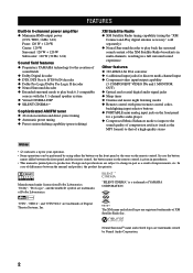
.... The XM name and related logos are subject to change in parentheses. • This manual is a trademark of YAMAHA CORPORATION. In case the button names differ between the manual and product, the product has priority. FEATURES FEATURES Built-in 6-channel... power amplifier ◆ Minimum RMS output power (0.9% THD, 1 kHz, 6 Ω) Front: 120 W + 120 W Center: 120 W Surround: 120 W + 120 W Subwoofer: 120 W (30 Hz, 6 Ω) Sound field features ◆ Proprietary YAMAHA technology for the creation of sound fields ◆ ...
.... The XM name and related logos are subject to change in parentheses. • This manual is a trademark of YAMAHA CORPORATION. In case the button names differ between the manual and product, the product has priority. FEATURES FEATURES Built-in 6-channel... power amplifier ◆ Minimum RMS output power (0.9% THD, 1 kHz, 6 Ω) Front: 120 W + 120 W Center: 120 W Surround: 120 W + 120 W Subwoofer: 120 W (30 Hz, 6 Ω) Sound field features ◆ Proprietary YAMAHA technology for the creation of sound fields ◆ ...
Owners Manual
Page 7
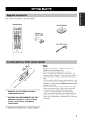
... memory is without batteries for more than 2 minutes, or if exhausted batteries remain in accordance with general house waste; GETTING STARTED Remote control POWER POWER TV AV STANDBY POWER CD MD/CD-R TUNER XM DVD DTV/CBL DVR V-AUX REC DISC SKIP CODE SET MULTI CH IN SLEEP AMP TV VOL CH VOLUME...
... memory is without batteries for more than 2 minutes, or if exhausted batteries remain in accordance with general house waste; GETTING STARTED Remote control POWER POWER TV AV STANDBY POWER CD MD/CD-R TUNER XM DVD DTV/CBL DVR V-AUX REC DISC SKIP CODE SET MULTI CH IN SLEEP AMP TV VOL CH VOLUME...
Owners Manual
Page 8
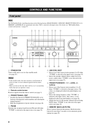
..." is selected as the input source (see page 33). 6 PRESET/TUNING/CH l / h, LEVEL +/- Notes • In the standby mode, this unit consumes a small amount of power in order to receive infrared signals from the remote control. • When you want to 8) when "TUNER" is displayed in the front panel display (see...
..." is selected as the input source (see page 33). 6 PRESET/TUNING/CH l / h, LEVEL +/- Notes • In the standby mode, this unit consumes a small amount of power in order to receive infrared signals from the remote control. • When you want to 8) when "TUNER" is displayed in the front panel display (see...
Owners Manual
Page 10
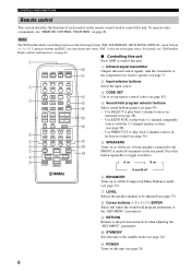
..." parameters. 9 RETURN Returns to the previous menu level when adjusting the "SET MENU" parameters. 0 STANDBY Sets this unit. A POWER Turns on the remote control used to control this button repeatedly to toggle as the input source. Press this unit.... POWER POWER TV AV STANDBY POWER 0 A 1 Infrared signal transmitter Outputs infrared control signals. RETURN XM MEMORY PRESET/CH A-E/CAT. DISPLAY B C D E F G H I 2 Input selector buttons Select the ...
..." parameters. 9 RETURN Returns to the previous menu level when adjusting the "SET MENU" parameters. 0 STANDBY Sets this unit. A POWER Turns on the remote control used to control this button repeatedly to toggle as the input source. Press this unit.... POWER POWER TV AV STANDBY POWER 0 A 1 Infrared signal transmitter Outputs infrared control signals. RETURN XM MEMORY PRESET/CH A-E/CAT. DISPLAY B C D E F G H I 2 Input selector buttons Select the ...
Owners Manual
Page 14
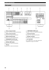
... VIDEO TUNER DVR OUT MONITOR OUT AM ANT GND FM ANT 75Ω UNBAL. See page 23 for connection information. 0 AC OUTLETS Use to supply power to your other audiovisual components.
... VIDEO TUNER DVR OUT MONITOR OUT AM ANT GND FM ANT 75Ω UNBAL. See page 23 for connection information. 0 AC OUTLETS Use to supply power to your other audiovisual components.
Owners Manual
Page 21
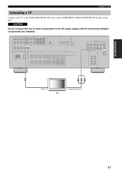
VIDEO MONITOR OUT COMPONENT VIDEO Y PB PR MONITOR OUT V Y PB PR Video in Component video in TV 17 PREPARATION CONNECTIONS Connecting a TV Connect your TV to the AC power supply until all connections between components are complete. CAUTION Do not connect this unit or other components to the VIDEO MONITOR OUT jack, or the COMPONENT VIDEO MONITOR OUT jacks of this unit.
VIDEO MONITOR OUT COMPONENT VIDEO Y PB PR MONITOR OUT V Y PB PR Video in Component video in TV 17 PREPARATION CONNECTIONS Connecting a TV Connect your TV to the AC power supply until all connections between components are complete. CAUTION Do not connect this unit or other components to the VIDEO MONITOR OUT jack, or the COMPONENT VIDEO MONITOR OUT jacks of this unit.
Owners Manual
Page 22
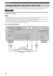
... example, if you connect your DVD player to both the DIGITAL INPUT (OPTICAL) and the DIGITAL INPUT (COAXIAL) jacks, priority is given to the AC power supply until all connections between components are examples of the STB. CAUTION Do not connect this unit, connect your other components to the signals input...
... example, if you connect your DVD player to both the DIGITAL INPUT (OPTICAL) and the DIGITAL INPUT (COAXIAL) jacks, priority is given to the AC power supply until all connections between components are examples of the STB. CAUTION Do not connect this unit, connect your other components to the signals input...
Owners Manual
Page 24
CAUTION Do not connect this unit or other than the default component assigned to the AC power supply until all connections between components are complete. Note To make a digital connection to a component other components to each DIGITAL INPUT jack, select the corresponding ...
CAUTION Do not connect this unit or other than the default component assigned to the AC power supply until all connections between components are complete. Note To make a digital connection to a component other components to each DIGITAL INPUT jack, select the corresponding ...
Owners Manual
Page 25
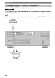
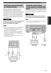
... console, a video camera or a portable audio player to the MULTI CH INPUT jacks. CAUTION Do not connect this unit and other components to the AC power supply until all connections between components are output only from a multi-format player, external decoder, sound processor or pre-amplifier. MULTI CH INPUT CENTER Connecting...
... console, a video camera or a portable audio player to the MULTI CH INPUT jacks. CAUTION Do not connect this unit and other components to the AC power supply until all connections between components are output only from a multi-format player, external decoder, sound processor or pre-amplifier. MULTI CH INPUT CENTER Connecting...
Owners Manual
Page 27
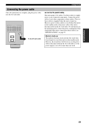
...To the AC wall outlet CONNECTIONS AC OUTLETS (SWITCHED) This unit equips 2 AC outlets. However, power to these outlets is supplied when this unit is in the standby mode. Use these outlets. Power to any connected components. However, the stored data will be connected to these outlets, see "...SPECIFICATIONS" on the maximum power or the total power consumption of your other components to these outlets to supply power to these outlets is cut off for more than one week. Memory back-up The memory back-...
...To the AC wall outlet CONNECTIONS AC OUTLETS (SWITCHED) This unit equips 2 AC outlets. However, power to these outlets is supplied when this unit is in the standby mode. Use these outlets. Power to any connected components. However, the stored data will be connected to these outlets, see "...SPECIFICATIONS" on the maximum power or the total power consumption of your other components to these outlets to supply power to these outlets is cut off for more than one week. Memory back-up The memory back-...
Owners Manual
Page 28
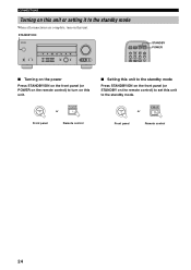
CONNECTIONS Turning on this unit or setting it to the standby mode. STANDBY /ON STANDBY or Front panel Remote control 24 STANDBY /ON POWER or Front panel Remote control ■ Setting this unit to the standby mode Press STANDBY/ON on the front panel (or STANDBY on the remote ... l PRESET/TUNING/CH h LEVEL INPUT MODE MEMORY MAN'L/AUTO FM TUNING MODE DISPLAY AUTO/MAN'L INPUT MULTI CH INPUT VOLUME VIDEO AUX VIDEO L AUDIO R PORTABLE POWER POWER TV AV STANDBY POWER CD MD/CD-R TUNER XM DVD DTV/CBL DVR V-AUX REC CODE SET MULTI CH IN STANDBY...
CONNECTIONS Turning on this unit or setting it to the standby mode. STANDBY /ON STANDBY or Front panel Remote control 24 STANDBY /ON POWER or Front panel Remote control ■ Setting this unit to the standby mode Press STANDBY/ON on the front panel (or STANDBY on the remote ... l PRESET/TUNING/CH h LEVEL INPUT MODE MEMORY MAN'L/AUTO FM TUNING MODE DISPLAY AUTO/MAN'L INPUT MULTI CH INPUT VOLUME VIDEO AUX VIDEO L AUDIO R PORTABLE POWER POWER TV AV STANDBY POWER CD MD/CD-R TUNER XM DVD DTV/CBL DVR V-AUX REC CODE SET MULTI CH IN STANDBY...
Owners Manual
Page 44
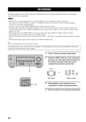
... input at the DIGITAL INPUT jacks are performed from CDs, radio, etc. INPUT 2 CD MD/CD-R TUNER or DVD DTV/CBL DVR V-AUX POWER POWER TV AV STANDBY POWER CD MD/CD-R TUNER XM DVD DTV/CBL DVR V-AUX REC CODE SET MULTI CH IN 2 Front panel Remote control 3 Start playback on the...
... input at the DIGITAL INPUT jacks are performed from CDs, radio, etc. INPUT 2 CD MD/CD-R TUNER or DVD DTV/CBL DVR V-AUX POWER POWER TV AV STANDBY POWER CD MD/CD-R TUNER XM DVD DTV/CBL DVR V-AUX REC CODE SET MULTI CH IN 2 Front panel Remote control 3 Start playback on the...

Owners Manual
Page 53
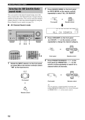
.... (Preset Search mode) Press A-E/CAT. j / i to change the channel category. Press PRESET/CH u / d to E). Press and hold for a channel within the selected category. POWER POWER TV AV STANDBY POWER CD MD/CD-R TUNER XM DVD DTV/CBL DVR V-AUX REC DISC SKIP CODE SET MULTI CH IN SLEEP 2 1 3 4 STEREO 1 MUSIC ENTERTAIN MOVIE 2 3 4 STANDARD...
.... (Preset Search mode) Press A-E/CAT. j / i to change the channel category. Press PRESET/CH u / d to E). Press and hold for a channel within the selected category. POWER POWER TV AV STANDBY POWER CD MD/CD-R TUNER XM DVD DTV/CBL DVR V-AUX REC DISC SKIP CODE SET MULTI CH IN SLEEP 2 1 3 4 STEREO 1 MUSIC ENTERTAIN MOVIE 2 3 4 STANDARD...
Owners Manual
Page 54
.../CH h LEVEL INPUT MODE MEMORY MAN'L/AUTO FM TUNING MODE DISPLAY AUTO/MAN'L INPUT MULTI CH INPUT VOLUME VIDEO AUX VIDEO L AUDIO R PORTABLE 31 POWER POWER TV AV STANDBY POWER CD MD/CD-R TUNER XM DVD DTV/CBL DVR V-AUX REC CODE SET MULTI CH IN 1 5 SPEAKERS 9 6 ENHANCER 0 7 8 NIGHT STRAIGHT 10 ENT. y You...
.../CH h LEVEL INPUT MODE MEMORY MAN'L/AUTO FM TUNING MODE DISPLAY AUTO/MAN'L INPUT MULTI CH INPUT VOLUME VIDEO AUX VIDEO L AUDIO R PORTABLE 31 POWER POWER TV AV STANDBY POWER CD MD/CD-R TUNER XM DVD DTV/CBL DVR V-AUX REC CODE SET MULTI CH IN 1 5 SPEAKERS 9 6 ENHANCER 0 7 8 NIGHT STRAIGHT 10 ENT. y You...
Owners Manual
Page 55
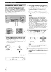
... Front panel Remote control BASIC OPERATION Lights up in the front panel display and the XM Satellite Radio information (such as the input source. POWER POWER TV AV STANDBY POWER CD MD/CD-R TUNER XM DVD DTV/CBL DVR V-AUX REC CODE SET MULTI CH IN 1 1 Rotate the INPUTselector on the front panel...
... Front panel Remote control BASIC OPERATION Lights up in the front panel display and the XM Satellite Radio information (such as the input source. POWER POWER TV AV STANDBY POWER CD MD/CD-R TUNER XM DVD DTV/CBL DVR V-AUX REC CODE SET MULTI CH IN 1 1 Rotate the INPUTselector on the front panel...
Owners Manual
Page 56
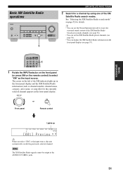
ENTER A-E/CAT. Front panel PRESET/CH Remote control y You can search for a channel within all channels. POWER POWER TV AV STANDBY POWER CD MD/CD-R TUNER XM DVD DTV/CBL DVR V-AUX REC CODE SET MULTI CH IN 1 5 SPEAKERS 9 6 ENHANCER 0 7 8 NIGHT STRAIGHT 10 ENT. A-E/CAT. j / i on the ...
ENTER A-E/CAT. Front panel PRESET/CH Remote control y You can search for a channel within all channels. POWER POWER TV AV STANDBY POWER CD MD/CD-R TUNER XM DVD DTV/CBL DVR V-AUX REC CODE SET MULTI CH IN 1 5 SPEAKERS 9 6 ENHANCER 0 7 8 NIGHT STRAIGHT 10 ENT. A-E/CAT. j / i on the ...


