
Owner's Manual
Page 2
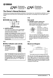
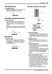
...panel 0). Neutrik NL4FC CHANNEL B 1+ B+ 1- P.15 ■ Other indicators and controls ^ Level Meter This LED display shows the level of the EMX5000-20, EMX5000-12 owner's manual have been revised. Check the output signal level via the internal power amplifier. The Owner's Manual Revisions E Thank you...the indicator will light before the Level Meter "8" or "PEAK" LED light. Use only Neutrik NL4FC plugs for purchasing the Yamaha EMX5000-20/EMX5000-12 Powered Mixer. The LIMITER indicator will light. P.14 ■ POWER amp section X X LIMITER indicator If the ...
...panel 0). Neutrik NL4FC CHANNEL B 1+ B+ 1- P.15 ■ Other indicators and controls ^ Level Meter This LED display shows the level of the EMX5000-20, EMX5000-12 owner's manual have been revised. Check the output signal level via the internal power amplifier. The Owner's Manual Revisions E Thank you...the indicator will light before the Level Meter "8" or "PEAK" LED light. Use only Neutrik NL4FC plugs for purchasing the Yamaha EMX5000-20/EMX5000-12 Powered Mixer. The LIMITER indicator will light. P.14 ■ POWER amp section X X LIMITER indicator If the ...
Owner's Manual
Page 7
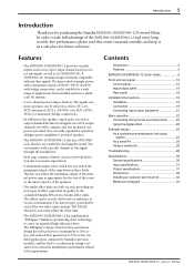
... an optional rack mount kit 32 Block/Level Diagram 33 EMX5000-20/EMX5000-12-Owner's Manual The signals output to the acclaimed Yamaha SPX series of the internal power amp as 16 (EMX5000-20), 8 (EMX5000-12) monaural input channels compatible with bridge connection), and is very useful for purchasing the Yamaha EMX5000-20/EMX5000-12 Powered Mixer. You can easily expand the system...
... an optional rack mount kit 32 Block/Level Diagram 33 EMX5000-20/EMX5000-12-Owner's Manual The signals output to the acclaimed Yamaha SPX series of the internal power amp as 16 (EMX5000-20), 8 (EMX5000-12) monaural input channels compatible with bridge connection), and is very useful for purchasing the Yamaha EMX5000-20/EMX5000-12 Powered Mixer. You can easily expand the system...
Owner's Manual
Page 9
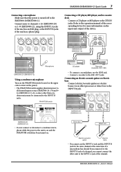
...off to the INPUT A jack of the channel. EMX5000-20 (EMX5000-12) Microphone EMX5000-20 (EMX5000-12) Using a condenser microphone Turn on the PHANTOM switch (located in the upper center corner on the input and output of the device. EMX5000-20/EMX5000-12-Owner's Manual PHANTOM switch CD player Recorder (Cassette, DAT... MD player, and/or cassette deck Connect a CD player or MD player to the operation manual of the corresponding device for the same channel at once (EMX5000-20: 1-8 and 9- 16, EMX5000-12: 1-8), so mics other than condenser mics must be connected to the REC OUT jacks....
...off to the INPUT A jack of the channel. EMX5000-20 (EMX5000-12) Microphone EMX5000-20 (EMX5000-12) Using a condenser microphone Turn on the PHANTOM switch (located in the upper center corner on the input and output of the device. EMX5000-20/EMX5000-12-Owner's Manual PHANTOM switch CD player Recorder (Cassette, DAT... MD player, and/or cassette deck Connect a CD player or MD player to the operation manual of the corresponding device for the same channel at once (EMX5000-20: 1-8 and 9- 16, EMX5000-12: 1-8), so mics other than condenser mics must be connected to the REC OUT jacks....
Owner's Manual
Page 10
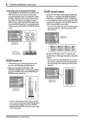
...YAMAHA SPEAKER PROCESSING switch in stereo. EMX5000-20/EMX5000-12-Owner's Manual EMX5000-20 (EMX5000-12) EMX5000-20 (EMX5000-12) Synthesizer, Drum machine, Guitar processor STEP 2 Power on 1 Turn on . Refer to the diagram below to make a stereo connection from the microphone. 8 EMX5000-20/EMX5000-12 Quick Guide Connecting an electronic musical instrument To the EMX5000-20/EMX5000...the low range, turn it on the power to all external devices connected to the EMX5000-20/EMX5000-12. 2 Make sure that channel lights occasionally. • Do not press the 26dB PAD switch if sound is ...
...YAMAHA SPEAKER PROCESSING switch in stereo. EMX5000-20/EMX5000-12-Owner's Manual EMX5000-20 (EMX5000-12) EMX5000-20 (EMX5000-12) Synthesizer, Drum machine, Guitar processor STEP 2 Power on 1 Turn on . Refer to the diagram below to make a stereo connection from the microphone. 8 EMX5000-20/EMX5000-12 Quick Guide Connecting an electronic musical instrument To the EMX5000-20/EMX5000...the low range, turn it on the power to all external devices connected to the EMX5000-20/EMX5000-12. 2 Make sure that channel lights occasionally. • Do not press the 26dB PAD switch if sound is ...
Owner's Manual
Page 11
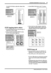
.... EMX5000-20/EMX5000-12-Owner's Manual EMX5000-20/EMX5000-12 Quick Guide 9 Use the ST OUT fader to adjust the volume of the speakers. 3 Set the EFFECT RTN fader to the "0" position. 3 EMX5000-20 (EMX5000-12) EMX5000-20 (EMX5000-12) STEP 4 Applying built-in effects 1 Use the PROGRAM selector to select the type of effect that you set the faders of the channel to...
.... EMX5000-20/EMX5000-12-Owner's Manual EMX5000-20/EMX5000-12 Quick Guide 9 Use the ST OUT fader to adjust the volume of the speakers. 3 Set the EFFECT RTN fader to the "0" position. 3 EMX5000-20 (EMX5000-12) EMX5000-20 (EMX5000-12) STEP 4 Applying built-in effects 1 Use the PROGRAM selector to select the type of effect that you set the faders of the channel to...
Owner's Manual
Page 12
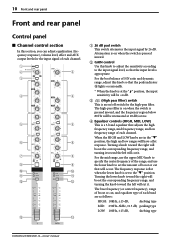
...15 dB, shelving type MID: 250Hz-5kHz, ±15 dB, peaking type LOW: 100Hz, ±15 dB, shelving type EMX5000-20/EMX5000-12-Owner's Manual Turning the lower knob toward the right will boost the corresponding frequency range, and turning the knob toward the left will cut it... switch is pressed inward. 2 GAIN control Use this knob so that adjusts the high frequency range, mid frequency range, and low frequency range of each channel. 1 2* 2 3 4 4 5 5 6 6 7 8 9 9 0 0 A A B B C C 1 26 dB pad switch This switch attenuates the input signal by 26 dB. Turning a knob ...
...15 dB, shelving type MID: 250Hz-5kHz, ±15 dB, peaking type LOW: 100Hz, ±15 dB, shelving type EMX5000-20/EMX5000-12-Owner's Manual Turning the lower knob toward the right will boost the corresponding frequency range, and turning the knob toward the left will cut it... switch is pressed inward. 2 GAIN control Use this knob so that adjusts the high frequency range, mid frequency range, and low frequency range of each channel. 1 2* 2 3 4 4 5 5 6 6 7 8 9 9 0 0 A A B B C C 1 26 dB pad switch This switch attenuates the input signal by 26 dB. Turning a knob ...
Owner's Manual
Page 13
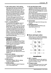
... is turned on . F ST (stereo) control The ST knob adjusts the amount of each channel will light 3 dB before the channel fader C) or post-fader (after the channel fader C). EMX5000-20/EMX5000-12-Owner's Manual It is also sent to the AUX1 and 2 buses. Note: If this switch is sent ...to monitor only a specific channel. D PHANTOM indicator This will light if a signal is off ...
... is turned on . F ST (stereo) control The ST knob adjusts the amount of each channel will light 3 dB before the channel fader C) or post-fader (after the channel fader C). EMX5000-20/EMX5000-12-Owner's Manual It is also sent to the AUX1 and 2 buses. Note: If this switch is sent ...to monitor only a specific channel. D PHANTOM indicator This will light if a signal is off ...
Owner's Manual
Page 16
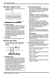
... and the line level signal that is a 9-band graphic equalizer that is a mix of the STEREO bus is significantly overloaded, which could result in two-channel power amplifier. V W V Graphic equalizer This is output from the SPEAKERS B 1/2 jacks. X Y Z X LIMITER indicator This indicator lights... SPEAKERS B 1/2 jacks. • MONO BRIDGE The monaural signal that allows you to adjust the tone of the STEREO bus signal. EMX5000-20/EMX5000-12-Owner's Manual s Power amp section This section allows you to select the signals that is a mix of the STEREO bus signals is adjusted by...
... and the line level signal that is a 9-band graphic equalizer that is a mix of the STEREO bus is significantly overloaded, which could result in two-channel power amplifier. V W V Graphic equalizer This is output from the SPEAKERS B 1/2 jacks. X Y Z X LIMITER indicator This indicator lights... SPEAKERS B 1/2 jacks. • MONO BRIDGE The monaural signal that allows you to adjust the tone of the STEREO bus signal. EMX5000-20/EMX5000-12-Owner's Manual s Power amp section This section allows you to select the signals that is a mix of the STEREO bus signals is adjusted by...
Owner's Manual
Page 17
...the STEREO bus to the desired position. The frequency is set this switch is output from channels 1-16 (EMX5000-20) or channels 1-8 (EMX5000-12). Use this switch is turned on. [ s Other indicators and controls ` s YAMAHA SPEAKER PROCESSING \ ON/OFF switch This switch enables you are sent from the ST OUT jacks...) you to the ST SUB OUT jacks and the SPEAKERS jacks. This will blink when this switch to the MONO OUT jack. EMX5000-20/EMX5000-12-Owner's Manual a PHONES control This knob adjusts the level of the slit in the control trimmer that is on or off. \ s STAND-...
...the STEREO bus to the desired position. The frequency is set this switch is output from channels 1-16 (EMX5000-20) or channels 1-8 (EMX5000-12). Use this switch is turned on. [ s Other indicators and controls ` s YAMAHA SPEAKER PROCESSING \ ON/OFF switch This switch enables you are sent from the ST OUT jacks...) you to the ST SUB OUT jacks and the SPEAKERS jacks. This will blink when this switch to the MONO OUT jack. EMX5000-20/EMX5000-12-Owner's Manual a PHONES control This knob adjusts the level of the slit in the control trimmer that is on or off. \ s STAND-...
Owner's Manual
Page 18
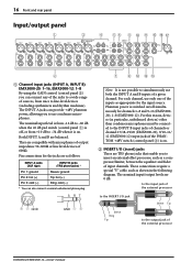
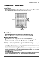
...as shown in particular, unbalanced devices) other than condenser microphones must be connected to the INPUT B input jacks of channels or channel 17/18-19/20 (EMX5000-20), 9/10-11/ 12 (EMX5000-12) input jacks if the PHANTOM +48V switch (control panel 3) is on . Phantom power is switched on/..., such as a compressor/limiter, between the equalizer and fader of input channels. The INPUT A jacks can provide +48V phantom power, allowing you to use both the INPUT A and B inputs of the external processor EMX5000-20/EMX5000-12-Owner's Manual Pin connections for the input source.
...as shown in particular, unbalanced devices) other than condenser microphones must be connected to the INPUT B input jacks of channels or channel 17/18-19/20 (EMX5000-20), 9/10-11/ 12 (EMX5000-12) input jacks if the PHANTOM +48V switch (control panel 3) is on . Phantom power is switched on/..., such as a compressor/limiter, between the equalizer and fader of input channels. The INPUT A jacks can provide +48V phantom power, allowing you to use both the INPUT A and B inputs of the external processor EMX5000-20/EMX5000-12-Owner's Manual Pin connections for the input source.
Owner's Manual
Page 19
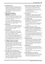
... to this jack. Connect an external mixer output here. The nominal input level is +4 dB. E FOOT SW EFFECT 2 ON/OFF jack A separately sold Yamaha FC5 foot switch can be connected to these jacks. Note: Use only the L jack to the STEREO bus. The signal adjusted by the AFL switches...line-level stereo signals to the two-channel built-in the upper part of an external effect unit such as a cassette deck and CD player, to be sent to adjust the final level of the signal output from these jacks. EMX5000-20/EMX5000-12-Owner's Manual The nominal input level is -10 ...
... to this jack. Connect an external mixer output here. The nominal input level is +4 dB. E FOOT SW EFFECT 2 ON/OFF jack A separately sold Yamaha FC5 foot switch can be connected to these jacks. Note: Use only the L jack to the STEREO bus. The signal adjusted by the AFL switches...line-level stereo signals to the two-channel built-in the upper part of an external effect unit such as a cassette deck and CD player, to be sent to adjust the final level of the signal output from these jacks. EMX5000-20/EMX5000-12-Owner's Manual The nominal input level is -10 ...
Owner's Manual
Page 20
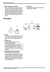
... controls in the master section of the control panel must be connected. EMX5000-20/EMX5000-12-Owner's Manual 18 Front and rear panel F FOOT SW (EFFECT 2) TAP jack When TAP DELAY is selected as the internal effect type for the EFFECT 2 RTN channel, you can be lowered to the minimum position. 3 SPEAKERS (speaker output) jacks...
... controls in the master section of the control panel must be connected. EMX5000-20/EMX5000-12-Owner's Manual 18 Front and rear panel F FOOT SW (EFFECT 2) TAP jack When TAP DELAY is selected as the internal effect type for the EFFECT 2 RTN channel, you can be lowered to the minimum position. 3 SPEAKERS (speaker output) jacks...
Owner's Manual
Page 21
... speakers connected to these respective jacks. • Two channel connections Use speakers with air intake on the right side and exhaust on the rear. When the power amp select switch is set of outputs. EMX5000-20/EMX5000-12-Owner's Manual Be sure to use cables designed for the purpose when... you connect speakers to the EMX5000-20/EMX5000-12. The speaker impedance requirement varies depending on the type of speaker cable you ...
... speakers connected to these respective jacks. • Two channel connections Use speakers with air intake on the right side and exhaust on the rear. When the power amp select switch is set of outputs. EMX5000-20/EMX5000-12-Owner's Manual Be sure to use cables designed for the purpose when... you connect speakers to the EMX5000-20/EMX5000-12. The speaker impedance requirement varies depending on the type of speaker cable you ...
Owner's Manual
Page 22
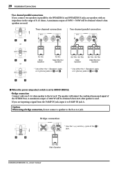
... speaker to the A1 jack. Caution: When using a bridge connection, do not connect a speaker to the B or A 2 jack. 20 Installation/Connections • Two channel parallel connections If you are used . Two-channel connection Two-channel parallel connection or 4Ω-8Ω 4Ω-8Ω 8Ω-16Ω 8Ω-16Ω 8Ω-16Ω 8Ω-16Ω... either the 1 (Speakon) jacks or 2 (phone) jacks of and . * Use either the 1 (Speakon) jacks or 2 (phone) jacks of the 1 jack. 8Ω-16Ω Main Speaker EMX5000-20/EMX5000-12-Owner's Manual
... speaker to the A1 jack. Caution: When using a bridge connection, do not connect a speaker to the B or A 2 jack. 20 Installation/Connections • Two channel parallel connections If you are used . Two-channel connection Two-channel parallel connection or 4Ω-8Ω 4Ω-8Ω 8Ω-16Ω 8Ω-16Ω 8Ω-16Ω 8Ω-16Ω... either the 1 (Speakon) jacks or 2 (phone) jacks of and . * Use either the 1 (Speakon) jacks or 2 (phone) jacks of the 1 jack. 8Ω-16Ω Main Speaker EMX5000-20/EMX5000-12-Owner's Manual

Owner's Manual
Page 24
... LEVEL control to adjust the maximum level of the speakers. 6 If you wish to adjust the tone of all the way down . EMX5000-20/EMX5000-12-Owner's Manual Check to see if the Power amp select switch on the power to which you set to ST L-R. 2 Connect cables to the desired.... Note: The volume level is set the equalizers, check the peak level indicator and adjust the ST fader if necessary. Note: You cannot use channel 1-16 (EMX5000-20), 1-8 (EMX5000-12) INPUT A and B jacks at the maximum volume. 5 Raise the ST OUT fader in the digital effect section are turned down , lower the...
... LEVEL control to adjust the maximum level of the speakers. 6 If you wish to adjust the tone of all the way down . EMX5000-20/EMX5000-12-Owner's Manual Check to see if the Power amp select switch on the power to which you set to ST L-R. 2 Connect cables to the desired.... Note: The volume level is set the equalizers, check the peak level indicator and adjust the ST fader if necessary. Note: You cannot use channel 1-16 (EMX5000-20), 1-8 (EMX5000-12) INPUT A and B jacks at the maximum volume. 5 Raise the ST OUT fader in the digital effect section are turned down , lower the...

Owner's Manual
Page 27
EMX5000-20/EMX5000-12-Owner's Manual s Playing back a CD player 1 Turn on the power to the peripheral devices, then to the EMX5000-20/ EMX5000-12. 2 Start playback on the EMX5000-20/ EMX5000-12, connect the 2TR IN jacks of the EMX5000-20/EMX5000-12 to the output of the recording cassette deck. • Connect the main ...set the Power amp select switch to ST L-R. Then, raise the ST OUT fader to the "0" position, and adjust the channel 17/18 (EMX5000-20), 9/10 (EMX5000-12) fader so that the PEAK indicator below the GAIN control will light occasionally. 3 As appropriate for the size of the...
EMX5000-20/EMX5000-12-Owner's Manual s Playing back a CD player 1 Turn on the power to the peripheral devices, then to the EMX5000-20/ EMX5000-12. 2 Start playback on the EMX5000-20/ EMX5000-12, connect the 2TR IN jacks of the EMX5000-20/EMX5000-12 to the output of the recording cassette deck. • Connect the main ...set the Power amp select switch to ST L-R. Then, raise the ST OUT fader to the "0" position, and adjust the channel 17/18 (EMX5000-20), 9/10 (EMX5000-12) fader so that the PEAK indicator below the GAIN control will light occasionally. 3 As appropriate for the size of the...
Owner's Manual
Page 29
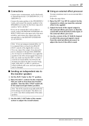
...processor so that you turn down all the way down for the channels to which the effect sound is independent of the main speakers. 3 Use the AUX 1 OUT fader of the effect sound. EMX5000-20/EMX5000-12-Owner's Manual Set the Power amp select switch to "AUX 1-MONO." •... If you want to use an external effect such as keyboards, to channel input jacks 1-20 (EMX5000-20), 1-12 (EMX5000-12). • Connect the main speakers to the SPEAKERSB 1/ ...
...processor so that you turn down all the way down for the channels to which the effect sound is independent of the main speakers. 3 Use the AUX 1 OUT fader of the effect sound. EMX5000-20/EMX5000-12-Owner's Manual Set the Power amp select switch to "AUX 1-MONO." •... If you want to use an external effect such as keyboards, to channel input jacks 1-20 (EMX5000-20), 1-12 (EMX5000-12). • Connect the main speakers to the SPEAKERSB 1/ ...
Owner's Manual
Page 31
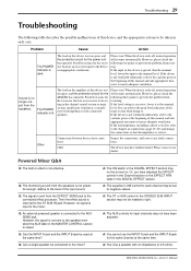
... Channel section or the EFFECT RTN fader in the MASTER CONTROL section is raised. sive load are an excessive level set to negative values. You can refer to the peak level indicators of the cient load impedance of 4-8 ohms. EMX5000-20/EMX5000-12-Owner's Manual ...Troubleshooting 29 Troubleshooting The following table describes the possible malfunctions of this device, and the appropriate actions to be turned on connections (page 19-20) and change the connections so that the impedance ...
... Channel section or the EFFECT RTN fader in the MASTER CONTROL section is raised. sive load are an excessive level set to negative values. You can refer to the peak level indicators of the cient load impedance of 4-8 ohms. EMX5000-20/EMX5000-12-Owner's Manual ...Troubleshooting 29 Troubleshooting The following table describes the possible malfunctions of this device, and the appropriate actions to be turned on connections (page 19-20) and change the connections so that the impedance ...
Owner's Manual
Page 32
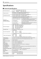
... (balanced input) FC5 (Foot switch), RK-124 (EMX5000-12) USA and Canada:120 V AC 60 Hz, 400 W Europe: 230 V AC 50 Hz, 550 W Other: 240 V AC 50 Hz, 550 W EMX5000-20/EMX5000-12-Owner's Manual 30 Specifications Specifications s General specifications ...Maximum output power Frequency response Total harmonic distortion Hum & noise (Average, Rs=150Ω) (with 20 Hz-20 kHz BPF) Maximum voltage gain Crosstalk at 1 kHz Input channel equalization ST Input channel ...
... (balanced input) FC5 (Foot switch), RK-124 (EMX5000-12) USA and Canada:120 V AC 60 Hz, 400 W Europe: 230 V AC 50 Hz, 550 W Other: 240 V AC 50 Hz, 550 W EMX5000-20/EMX5000-12-Owner's Manual 30 Specifications Specifications s General specifications ...Maximum output power Frequency response Total harmonic distortion Hum & noise (Average, Rs=150Ω) (with 20 Hz-20 kHz BPF) Maximum voltage gain Crosstalk at 1 kHz Input channel equalization ST Input channel ...


