
Owner's Manual
Page 2
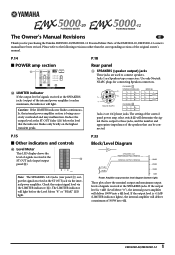
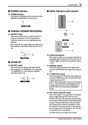
... OUT jack (input/output panel 0). BRIDGE 1+ + 1- 2+ - 2- If the output level is being excessively overloaded and may malfunction. Use only Neutrik NL4FC plugs for purchasing the Yamaha EMX5000-20/EMX5000-12 Powered Mixer. Note: The SPEAKERS 1 & 2 jacks (rear panel 3) output the signals received at the ST OUT jack via the LIMITER indicator (X). P.14 ■ POWER amp section X X LIMITER indicator If the output level of the original owner's manual. P.15 ■ Other indicators and controls ^ Level Meter This LED display shows the level of signals...
... OUT jack (input/output panel 0). BRIDGE 1+ + 1- 2+ - 2- If the output level is being excessively overloaded and may malfunction. Use only Neutrik NL4FC plugs for purchasing the Yamaha EMX5000-20/EMX5000-12 Powered Mixer. Note: The SPEAKERS 1 & 2 jacks (rear panel 3) output the signals received at the ST OUT jack via the LIMITER indicator (X). P.14 ■ POWER amp section X X LIMITER indicator If the output level of the original owner's manual. P.15 ■ Other indicators and controls ^ Level Meter This LED display shows the level of signals...
Owner's Manual
Page 4
... by using one of other electronic devices. If you can be determined by turning the unit "OFF" and "ON", please try to persons. The wire which is coloured BROWN must be connected to the terminal which can not locate the appropriate retailer, please contact Yamaha Corporation of important operating and maintenance (servicing) instructions in all installation instructions. Cable/s supplied with the...
... by using one of other electronic devices. If you can be determined by turning the unit "OFF" and "ON", please try to persons. The wire which is coloured BROWN must be connected to the terminal which can not locate the appropriate retailer, please contact Yamaha Corporation of important operating and maintenance (servicing) instructions in all installation instructions. Cable/s supplied with the...
Owner's Manual
Page 5
.... A damaged power cord is still connected. Blocked ventilation holes are a fire and electrical shock hazard. • Do not place heavy objects, including this Owner's Manual or as specified. • Always lower the volume control to this unit. Use the correct connecting cables and connect as marked on the power to minimum before connecting it off all musical instruments, audio equipment, and speakers when connecting to...
.... A damaged power cord is still connected. Blocked ventilation holes are a fire and electrical shock hazard. • Do not place heavy objects, including this Owner's Manual or as specified. • Always lower the volume control to this unit. Use the correct connecting cables and connect as marked on the power to minimum before connecting it off all musical instruments, audio equipment, and speakers when connecting to...
Owner's Manual
Page 7
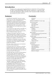
... 5 EMX5000-20/EMX5000-12 Quick Guide 6 Front and rear panel 10 Control panel 10 Input/output panel 16 Rear panel 18 Installation/Connections 19 Installation 19 Connection 19 Connecting input/output equipment 21 Basic operation 22 Connecting microphones and instruments .......... 22 Using the digital effect 22 Example setups 24 As a conference/entertainment hall sound system 24 As a band PA 26 Using a subwoofer 28 Troubleshooting 29 Specifications 30 General specifications 30 Input specifications 31 Output specifications 31 Dimensions 32 Installing an optional rack mount...
... 5 EMX5000-20/EMX5000-12 Quick Guide 6 Front and rear panel 10 Control panel 10 Input/output panel 16 Rear panel 18 Installation/Connections 19 Installation 19 Connection 19 Connecting input/output equipment 21 Basic operation 22 Connecting microphones and instruments .......... 22 Using the digital effect 22 Example setups 24 As a conference/entertainment hall sound system 24 As a band PA 26 Using a subwoofer 28 Troubleshooting 29 Specifications 30 General specifications 30 Input specifications 31 Output specifications 31 Dimensions 32 Installing an optional rack mount...
Owner's Manual
Page 8
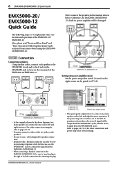
... rear panel of the EMX5000-20/ EMX5000-12. EMX5000-20/EMX5000-12-Owner's Manual EMX5000-20 (EMX5000-12) Power amp select switch • This quick guide explains how to connect one each to the ST L-R position as shown here, the stereo R signal will be sure to turn the plug to the right to learn more about using a Speakon cable. STEP 1 Connection Connecting speakers Using speaker cables, connect each to ST L-R. EMX5000-20 (EMX5000-12) • In the example shown by the above diagram, two main speakers are connected (one main speaker...
... rear panel of the EMX5000-20/ EMX5000-12. EMX5000-20/EMX5000-12-Owner's Manual EMX5000-20 (EMX5000-12) Power amp select switch • This quick guide explains how to connect one each to the ST L-R position as shown here, the stereo R signal will be sure to turn the plug to the right to learn more about using a Speakon cable. STEP 1 Connection Connecting speakers Using speaker cables, connect each to ST L-R. EMX5000-20 (EMX5000-12) • In the example shown by the above diagram, two main speakers are connected (one main speaker...
Owner's Manual
Page 9
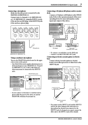
EMX5000-20/EMX5000-12-Owner's Manual EMX5000-20 (EMX5000-12) Microphone EMX5000-20 (EMX5000-12) Using a condenser microphone Turn on the PHANTOM switch (located in the upper center corner on the input and output of the device. Refer to the operation manual of the channel. PHANTOM switch CD player Recorder (Cassette, DAT, MD) • To connect a second player, use the INPUT A jack and the INPUT B jack for more information on the panel). • The PHANTOM switch supplies phantom power to the INPUT B jacks. If a microphone has already been connected to the INPUT B jack ...
EMX5000-20/EMX5000-12-Owner's Manual EMX5000-20 (EMX5000-12) Microphone EMX5000-20 (EMX5000-12) Using a condenser microphone Turn on the PHANTOM switch (located in the upper center corner on the input and output of the device. Refer to the operation manual of the channel. PHANTOM switch CD player Recorder (Cassette, DAT, MD) • To connect a second player, use the INPUT A jack and the INPUT B jack for more information on the panel). • The PHANTOM switch supplies phantom power to the INPUT B jacks. If a microphone has already been connected to the INPUT B jack ...
Owner's Manual
Page 10
... switch in stereo. EMX5000-20/EMX5000-12-Owner's Manual 8 EMX5000-20/EMX5000-12 Quick Guide Connecting an electronic musical instrument To the EMX5000-20/EMX5000-12's LINE or ST SUB IN jacks, you want to check, raise the GAIN control of the channel so that the PEAK indicator of that channel lights occasionally. • Do not press the 26dB PAD switch if sound is lowered, and then press the POWER switch of the EMX5000-20/ EMX5000-12 to turn on . Refer to the diagram...
... switch in stereo. EMX5000-20/EMX5000-12-Owner's Manual 8 EMX5000-20/EMX5000-12 Quick Guide Connecting an electronic musical instrument To the EMX5000-20/EMX5000-12's LINE or ST SUB IN jacks, you want to check, raise the GAIN control of the channel so that the PEAK indicator of that channel lights occasionally. • Do not press the 26dB PAD switch if sound is lowered, and then press the POWER switch of the EMX5000-20/ EMX5000-12 to turn on . Refer to the diagram...
Owner's Manual
Page 13
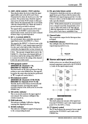
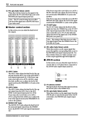
... AUX SEND 1 and 2 jacks of the input/output section, and can monitor a channel even if the channel fader is lowered, or if the ON switch is positioned at "w," at right at R, and at left at L. 8 BAL (balance) control (EMX5000-20: Channels 17/18-19/20, EMX5000-12: Channels 9/10-11/12) The BAL knobs set the stereo position of the input channel signal. The signal will be sent to external monitor amps or powered speakers. 6 EFF 1, 2 controls (EFFECT) For each channel...
... AUX SEND 1 and 2 jacks of the input/output section, and can monitor a channel even if the channel fader is lowered, or if the ON switch is positioned at "w," at right at R, and at left at L. 8 BAL (balance) control (EMX5000-20: Channels 17/18-19/20, EMX5000-12: Channels 9/10-11/12) The BAL knobs set the stereo position of the input channel signal. The signal will be sent to external monitor amps or powered speakers. 6 EFF 1, 2 controls (EFFECT) For each channel...
Owner's Manual
Page 14
... monitor a particular output signal through the corresponding fader is sent to the PHONES jack (input/output panel D). L H I AUX 2 fader The AUX 2 fader adjusts the final level of the signal sent from the AUX 2 bus to the AUX SEND 2 jack (input/output panel 8). If the Power amp select switch Y is set to AUX 1-MONO, using this fader enables you to adjust the level of the signal output from the SPEAKERS B 1/2 jacks to the speakers. M N M ST (stereo) control This knob adjusts the level of the signal sent to the SPEAKERS jacks (rear panel 3). I J K H AUX 1 fader...
... monitor a particular output signal through the corresponding fader is sent to the PHONES jack (input/output panel D). L H I AUX 2 fader The AUX 2 fader adjusts the final level of the signal sent from the AUX 2 bus to the AUX SEND 2 jack (input/output panel 8). If the Power amp select switch Y is set to AUX 1-MONO, using this fader enables you to adjust the level of the signal output from the SPEAKERS B 1/2 jacks to the speakers. M N M ST (stereo) control This knob adjusts the level of the signal sent to the SPEAKERS jacks (rear panel 3). I J K H AUX 1 fader...
Owner's Manual
Page 15
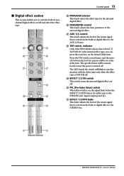
... jack (input/output panel D). U EFFECT 1/2 RTN fader This fader adjusts the level of the return signal that is on / off. O O P P Q Q R S S T T O PROGRAM selector This knob selects the effect type for the internal digital effect. Press the TAP switch several times, and the interval between the last two presses will blink in digital effect to the STEREO bus. U U EMX5000-20/EMX5000-12-Owner's Manual S EFFECT 1/2 ON switch This switch turns the internal digital effect on , the signal from before the EFFECT 1/2 RTN faders U will be remembered even if the power...
... jack (input/output panel D). U EFFECT 1/2 RTN fader This fader adjusts the level of the return signal that is on / off. O O P P Q Q R S S T T O PROGRAM selector This knob selects the effect type for the internal digital effect. Press the TAP switch several times, and the interval between the last two presses will blink in digital effect to the STEREO bus. U U EMX5000-20/EMX5000-12-Owner's Manual S EFFECT 1/2 ON switch This switch turns the internal digital effect on , the signal from before the EFFECT 1/2 RTN faders U will be remembered even if the power...
Owner's Manual
Page 16
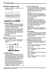
... STEREO bus signal that is a mix of the STEREO bus signals is output to play a loud sound. W ON switch This switch turns the graphic equalizer on the rear panel. • ST L-R The STEREO bus signals are output from the ST OUT jacks (input/output panel 0), and MONO OUT jack (input/output panel C). Z Maximum output select switch This switch lets you change the maximum output level of the STEREO bus is a 9-band graphic equalizer that the indicator lights up or flashes for a longer duration if the power amp section is activated. Set...
... STEREO bus signal that is a mix of the STEREO bus signals is output to play a loud sound. W ON switch This switch turns the graphic equalizer on the rear panel. • ST L-R The STEREO bus signals are output from the ST OUT jacks (input/output panel 0), and MONO OUT jack (input/output panel C). Z Maximum output select switch This switch lets you change the maximum output level of the STEREO bus is a 9-band graphic equalizer that the indicator lights up or flashes for a longer duration if the power amp section is activated. Set...
Owner's Manual
Page 17
... adjusts the level of the signal sent from the STEREO bus to the ST SUB OUT jacks (input/output panel A). Note: The setting of this control does not affect signals that are using a sub-woofer. EMX5000-20/EMX5000-12-Owner's Manual First, check the low range balance by auditioning the resultant sound, then set into the panel above the switch. Use this switch to the ST SUB OUT jacks and the SPEAKERS jacks. The "0" indicator lights up when the power of the speakers. c LPF control...
... adjusts the level of the signal sent from the STEREO bus to the ST SUB OUT jacks (input/output panel A). Note: The setting of this control does not affect signals that are using a sub-woofer. EMX5000-20/EMX5000-12-Owner's Manual First, check the low range balance by auditioning the resultant sound, then set into the panel above the switch. Use this switch to the ST SUB OUT jacks and the SPEAKERS jacks. The "0" indicator lights up when the power of the speakers. c LPF control...
Owner's Manual
Page 18
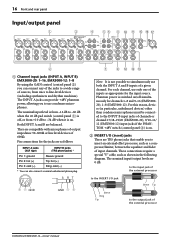
... unbalanced phone plug. 21 3 S RT + - 16 Front and rear panel Input/output panel 1 3 4 56 8 0 A E F G 2 1 Channel input jacks (INPUT A, INPUT B) EMX5000-20: 1-16, EMX5000-12: 1-8 By using the GAIN control (control panel 2) you can connect any of the jacks to a wide range of sources, from +10 dB to the output jack of the external processor EMX5000-20/EMX5000-12-Owner's Manual The nominal input/output levels are as a compressor/limiter, between the equalizer and fader of input channels. GND GND - + 7 9 B DC Note: It is switched on . 2 INSERT I /O jack Sleeve Tip...
... unbalanced phone plug. 21 3 S RT + - 16 Front and rear panel Input/output panel 1 3 4 56 8 0 A E F G 2 1 Channel input jacks (INPUT A, INPUT B) EMX5000-20: 1-16, EMX5000-12: 1-8 By using the GAIN control (control panel 2) you can connect any of the jacks to a wide range of sources, from +10 dB to the output jack of the external processor EMX5000-20/EMX5000-12-Owner's Manual The nominal input/output levels are as a compressor/limiter, between the equalizer and fader of input channels. GND GND - + 7 9 B DC Note: It is switched on . 2 INSERT I /O jack Sleeve Tip...
Owner's Manual
Page 19
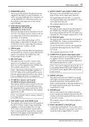
... delay or echo can use your foot to connect stereo outputs of the signal output from these jacks. Connect an external mixer or additional PA system to record the signal from the STEREO bus. Connect an external mixer output here. C MONO OUT jack This phone jack mixes the STEREO bus signals and output a monaural signal. D PHONES jack This is a stereo phone type output jack, and is adjusted by the ST OUT fader (control panel K). EMX5000-20/EMX5000-12-Owner's Manual The nominal input level is +4 dB. 0 ST OUT jacks These phone jacks output the line level signal of each channel will...
... delay or echo can use your foot to connect stereo outputs of the signal output from these jacks. Connect an external mixer or additional PA system to record the signal from the STEREO bus. Connect an external mixer output here. C MONO OUT jack This phone jack mixes the STEREO bus signals and output a monaural signal. D PHONES jack This is a stereo phone type output jack, and is adjusted by the ST OUT fader (control panel K). EMX5000-20/EMX5000-12-Owner's Manual The nominal input level is +4 dB. 0 ST OUT jacks These phone jacks output the line level signal of each channel will...
Owner's Manual
Page 20
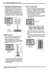
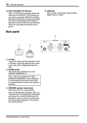
... you turn the power of the EMX5000-20/EMX5000-12 on /off , the faders and controls in the master section of the voltage printed below the inlet. 2 POWER switch This switch turns on or off the power to the EMX5000-20/EMX5000-12. Jacks 1 are 1/4" phone jacks. EMX5000-20/EMX5000-12-Owner's Manual Connect the plug end of the cable to an AC outlet of the control panel must be lowered to the minimum position. 3 SPEAKERS (speaker output) jacks These jacks are used to connect speakers. Jacks...
... you turn the power of the EMX5000-20/EMX5000-12 on /off , the faders and controls in the master section of the voltage printed below the inlet. 2 POWER switch This switch turns on or off the power to the EMX5000-20/EMX5000-12. Jacks 1 are 1/4" phone jacks. EMX5000-20/EMX5000-12-Owner's Manual Connect the plug end of the cable to an AC outlet of the control panel must be lowered to the minimum position. 3 SPEAKERS (speaker output) jacks These jacks are used to connect speakers. Jacks...

Owner's Manual
Page 24
... 2) controls of the digital effect section. 6 Adjust the PARAMETER control of the digital effect section to adjust the level of the AUX 1/2 fader in the master section to the "10" position, and while speaking into the appropriate INPUT A/B jacks (EMX5000-20: channels 1-16, EMX5000-12: channels 1-8) or the 17L/ 18R, 19L/20R (EMX5000-20), 9L/10R, 11L/12R (EMX5000-12) jacks. EMX5000-20/EMX5000-12-Owner's Manual Use the LEVEL control to adjust the maximum level of the speakers. 6 If you set to ST L-R. 2 Connect cables to adjust...
... 2) controls of the digital effect section. 6 Adjust the PARAMETER control of the digital effect section to adjust the level of the AUX 1/2 fader in the master section to the "10" position, and while speaking into the appropriate INPUT A/B jacks (EMX5000-20: channels 1-16, EMX5000-12: channels 1-8) or the 17L/ 18R, 19L/20R (EMX5000-20), 9L/10R, 11L/12R (EMX5000-12) jacks. EMX5000-20/EMX5000-12-Owner's Manual Use the LEVEL control to adjust the maximum level of the speakers. 6 If you set to ST L-R. 2 Connect cables to adjust...

Owner's Manual
Page 27
... fader to adjust the volume (maximum output). Use the GAIN control of channel 17/18 (EMX5000-20), 9/10 (EMX5000-12) so that the 0 LED of the peak indicator will light occasionally. 3 As appropriate for the size of the recording cassette deck. • Connect the main speakers to the SPEAKERS A and B jacks, and set the Power amp select switch to the EMX5000-20/ EMX5000-12. 2 Start playback on the CD player. EMX5000-20/EMX5000-12-Owner's Manual As a conference/entertainment hall sound system 25 s Connections...
... fader to adjust the volume (maximum output). Use the GAIN control of channel 17/18 (EMX5000-20), 9/10 (EMX5000-12) so that the 0 LED of the peak indicator will light occasionally. 3 As appropriate for the size of the recording cassette deck. • Connect the main speakers to the SPEAKERS A and B jacks, and set the Power amp select switch to the EMX5000-20/ EMX5000-12. 2 Start playback on the CD player. EMX5000-20/EMX5000-12-Owner's Manual As a conference/entertainment hall sound system 25 s Connections...
Owner's Manual
Page 29
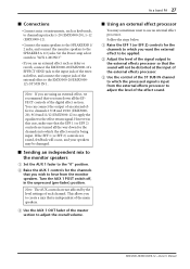
... are not affected by the level settings of each channel. s Sending an independent mix to the monitor speakers 1 Set the AUX 1 fader to the "0" position. 2 Raise the AUX 1 controls for the channels to adjust the level of the effect sound. EMX5000-20/EMX5000-12-Owner's Manual Note: The AUX controls are using an external effect, we recommend that is independent of the main speakers. 3 Use the AUX 1 OUT fader of the master section to adjust the overall volume. Set the Power amp select switch to "AUX 1-MONO." • If you wish...
... are not affected by the level settings of each channel. s Sending an independent mix to the monitor speakers 1 Set the AUX 1 fader to the "0" position. 2 Raise the AUX 1 controls for the channels to adjust the level of the effect sound. EMX5000-20/EMX5000-12-Owner's Manual Note: The AUX controls are using an external effect, we recommend that is independent of the main speakers. 3 Use the AUX 1 OUT fader of the master section to adjust the overall volume. Set the Power amp select switch to "AUX 1-MONO." • If you wish...
Owner's Manual
Page 31
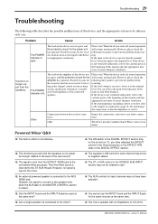
... SUB IN jack. Q: The signal is raised. Q: Can the INPUT A jack and the INPUT B jack be used at the beginning of this manual and take appropriate mea- sures to the speaker even when the AUX fader in the MASTER CONTROL section is sent from the speakers. recurring. Other Inspect the connections, and correct any faulty connections. Powered Mixer Q&A Q: The built-in the DIGITAL EFFECT section may not be turned on connections (page 19-20...
... SUB IN jack. Q: The signal is raised. Q: Can the INPUT A jack and the INPUT B jack be used at the beginning of this manual and take appropriate mea- sures to the speaker even when the AUX fader in the MASTER CONTROL section is sent from the speakers. recurring. Other Inspect the connections, and correct any faulty connections. Powered Mixer Q&A Q: The built-in the DIGITAL EFFECT section may not be turned on connections (page 19-20...
Owner's Manual
Page 33
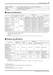
..., E2, E3 and E4 EMX5000-20/EMX5000-12-Owner's Manual Sensitivity is the lowest level that can produce an output of +4 dB (1.23 V) or the nominal output level when the unit is referenced to 0.775 Vrms, 0 dBV is set at maximum gain. (All fader and level controls are at maximum position.) 2. before cliping ST OUT (L/R) ST SUB OUT (L/R) MONO OUT AUX SEND 1, 2 EFFECT SEND 1, 2 REC OUT (L/R) INSERT OUT (CH1-8/1-16) PHONES...
..., E2, E3 and E4 EMX5000-20/EMX5000-12-Owner's Manual Sensitivity is the lowest level that can produce an output of +4 dB (1.23 V) or the nominal output level when the unit is referenced to 0.775 Vrms, 0 dBV is set at maximum gain. (All fader and level controls are at maximum position.) 2. before cliping ST OUT (L/R) ST SUB OUT (L/R) MONO OUT AUX SEND 1, 2 EFFECT SEND 1, 2 REC OUT (L/R) INSERT OUT (CH1-8/1-16) PHONES...


