

Owner's Manual
Page 1
Owner's Manual MIC LINE INS I/O 1 MIC LINE INS I/O 2 MIC LINE INS I/O 3 INPUT MIC MIC MIC LINE INS I/O 4 LINE LINE 0dB INSERT I/O 5 OUT IN 6 MIC LINE 7 MIC 9 L B LINE 8 10 R B 9 L (MONO) A 10 R A 9/10 11 L (MONO) A 12 R A 11/12 11 L B L TAPE 12 R R B L (MONO) R ST SUB 1 +4dB OUTPUT L L REC -10dBV L R L (MONO) MONI 1 R ST SUB 2 +4dB L BRIDGE R ST 1 +4dB R ST 2 +4dB MONI 2 +4dB R PAMP IN +4dB FOOT SW MONO +4dB EFFECT +4dB PHONES/ C-R OUT (+4dB) EEEngine GAIN GAIN GAIN GAIN GAIN GAIN GAIN GAIN A B GAIN +10 -16 -34 -60 +10 -16 -34 -60 +10...
Owner's Manual MIC LINE INS I/O 1 MIC LINE INS I/O 2 MIC LINE INS I/O 3 INPUT MIC MIC MIC LINE INS I/O 4 LINE LINE 0dB INSERT I/O 5 OUT IN 6 MIC LINE 7 MIC 9 L B LINE 8 10 R B 9 L (MONO) A 10 R A 9/10 11 L (MONO) A 12 R A 11/12 11 L B L TAPE 12 R R B L (MONO) R ST SUB 1 +4dB OUTPUT L L REC -10dBV L R L (MONO) MONI 1 R ST SUB 2 +4dB L BRIDGE R ST 1 +4dB R ST 2 +4dB MONI 2 +4dB R PAMP IN +4dB FOOT SW MONO +4dB EFFECT +4dB PHONES/ C-R OUT (+4dB) EEEngine GAIN GAIN GAIN GAIN GAIN GAIN GAIN GAIN A B GAIN +10 -16 -34 -60 +10 -16 -34 -60 +10...
Owner's Manual
Page 2
... not installed and used . If the antenna lead-in is coloured BLUE must be connected to follow instructions could void your authority, granted by YAMAHA KEMBLE MUSIC (U.K.) LTD. If you can be connected to the operation of product. Follow all installations. If this product or the device that interference will not result in FCC Regulations, Part 15 for Class "B" digital devices...
... not installed and used . If the antenna lead-in is coloured BLUE must be connected to follow instructions could void your authority, granted by YAMAHA KEMBLE MUSIC (U.K.) LTD. If you can be connected to the operation of product. Follow all installations. If this product or the device that interference will not result in FCC Regulations, Part 15 for Class "B" digital devices...
Owner's Manual
Page 3
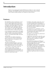
..., compared to Yamaha's previous models), and has lead to the amp. • A digital effect with mic/line signals. EMX2000-Owner's Manual Features • The EMX2000 provides versatile inputs, such as two stereo input channels and two stereo sub inputs, as well as stereo main (ST L-R), monitor+monaural main (MONI 1MONO), or monaural main (bridge connection). - You can easily expand the system by adding a power amplifier or powered speakers. • The EMX2000 also has a PHONES C-R OUT jack, which is...
..., compared to Yamaha's previous models), and has lead to the amp. • A digital effect with mic/line signals. EMX2000-Owner's Manual Features • The EMX2000 provides versatile inputs, such as two stereo input channels and two stereo sub inputs, as well as stereo main (ST L-R), monitor+monaural main (MONI 1MONO), or monaural main (bridge connection). - You can easily expand the system by adding a power amplifier or powered speakers. • The EMX2000 also has a PHONES C-R OUT jack, which is...
Owner's Manual
Page 4
... no user-serviceable parts. Do not open a vent hole. Contents Front and rear panel 4 Control panel 4 Input/output panel 9 Rear panel 11 Connections 12 Connecting speakers 12 Connecting input/output equipment...........12 Basic operation 13 Connecting microphones and instruments .13 Using the digital effect 13 Example setups 14 As a band PA 14 As a conference/entertainment hall sound system 15 Using a subwoofer 16 Specifications 17 General specifications 17 Input specifications 18 Output specifications 18 Dimensions 19 Block/Level Diagram 20 EMX2000-Owner's Manual Avoid...
... no user-serviceable parts. Do not open a vent hole. Contents Front and rear panel 4 Control panel 4 Input/output panel 9 Rear panel 11 Connections 12 Connecting speakers 12 Connecting input/output equipment...........12 Basic operation 13 Connecting microphones and instruments .13 Using the digital effect 13 Example setups 14 As a band PA 14 As a conference/entertainment hall sound system 15 Using a subwoofer 16 Specifications 17 General specifications 17 Input specifications 18 Output specifications 18 Dimensions 19 Block/Level Diagram 20 EMX2000-Owner's Manual Avoid...
Owner's Manual
Page 5
... frequency range, and low frequency range of each channel. If the power amp select switch V is appropriate. For the best balance of S/N ratio and dynamic range, adjust this knob so that the input level is in the "w" position. Note: The signal sent to the MONI 1 jack (input/output panel 9). The signal of the MONITOR 1 bus is also sent to the speakers connected to the MONI 2 jack (input/output panel 9). The base frequency...
... frequency range, and low frequency range of each channel. If the power amp select switch V is appropriate. For the best balance of S/N ratio and dynamic range, adjust this knob so that the input level is in the "w" position. Note: The signal sent to the MONI 1 jack (input/output panel 9). The signal of the MONITOR 1 bus is also sent to the speakers connected to the MONI 2 jack (input/output panel 9). The base frequency...

Owner's Manual
Page 6
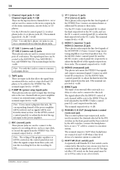
... signal that is sent to the EFFECT bus. The signal of the signal sent to the MONITOR 1/2 buses (pre-fader send). EMX2000-Owner's Manual This is useful when you can monitor the signal through the headphones. Note: The ST control setting does not affect the level of the EFFECT bus is sent to the EFFECT jack (input/output panel A). The switch operation does not affect the signal sent to the STEREO bus, MONITOR 1/2 buses, or the EFFECT bus. 0 Channel fader This controls the output level of the input channel signal. 5 6 Effect control (EFFECT) For each channel...
... signal that is sent to the EFFECT bus. The signal of the signal sent to the MONITOR 1/2 buses (pre-fader send). EMX2000-Owner's Manual This is useful when you can monitor the signal through the headphones. Note: The ST control setting does not affect the level of the EFFECT bus is sent to the EFFECT jack (input/output panel A). The switch operation does not affect the signal sent to the STEREO bus, MONITOR 1/2 buses, or the EFFECT bus. 0 Channel fader This controls the output level of the input channel signal. 5 6 Effect control (EFFECT) For each channel...

Owner's Manual
Page 7
...STEREO bus to the MONO jack (input/output panel 0). EMX2000-Owner's Manual If the Power amp select switch V is set to MONI 1-MONO, this switch is connected to the TAPE jacks (input/output panel 5). Note: The setting of this fader enables you can adjust the input level of the signal sent from the SPEAKERS R 1/2 jacks to the ST 1 jacks (input/output panel 8). 6 s Master control section In this fader also adjusts the level of the signal sent to the SPEAKERS jacks (rear panel 1). G EFFECT fader The EFFECT fader adjusts the final level of the signal output from the STEREO...
...STEREO bus to the MONO jack (input/output panel 0). EMX2000-Owner's Manual If the Power amp select switch V is set to MONI 1-MONO, this switch is connected to the TAPE jacks (input/output panel 5). Note: The setting of this fader enables you can adjust the input level of the signal sent from the SPEAKERS R 1/2 jacks to the ST 1 jacks (input/output panel 8). 6 s Master control section In this fader also adjusts the level of the signal sent to the SPEAKERS jacks (rear panel 1). G EFFECT fader The EFFECT fader adjusts the final level of the signal output from the STEREO...

Owner's Manual
Page 8
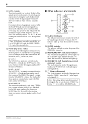
... switch This switch turns the internal digital effect on/ off . s Power amp section This section allows you to select the signals that is activated. N ST (stereo) control This knob adjusts the level of the signal output from the power amp section reaches the maximum and the limiter is output from the ST 1/2 jacks (input/output panel 8), and MONO jack (input/output panel 0). L POWER AMP R LIMITER LEVEL +18 +4 +18 +4 L/BRIDGE ST L MONI 1 ST R MONO MONO BRIDGE T U V T LIMITER indicator This indicator lights up when the level...
... switch This switch turns the internal digital effect on/ off . s Power amp section This section allows you to select the signals that is activated. N ST (stereo) control This knob adjusts the level of the signal output from the power amp section reaches the maximum and the limiter is output from the ST 1/2 jacks (input/output panel 8), and MONO jack (input/output panel 0). L POWER AMP R LIMITER LEVEL +18 +4 +18 +4 L/BRIDGE ST L MONI 1 ST R MONO MONO BRIDGE T U V T LIMITER indicator This indicator lights up when the level...
Owner's Manual
Page 9
... MIC input jacks for channels 1~8. V Power amp select switch Select one speaker to adjust the knob. The final level of these signals is adjusted by the master MONI 1 fader and the MONO fader. • MONO BRIDGE The monaural signal that will light up when the ouput level reaches +4 dB. Y PHANTOM (+48V) switch and indicator This switch turns the phantom power supply on . Z PHONES/C.R.OUT (headphones/control room out) control This knob adjusts the level of the signal monitored via the PHONES/C-R OUT jack (input/ output panel B). [ ST 2 (stereo 2) control...
... MIC input jacks for channels 1~8. V Power amp select switch Select one speaker to adjust the knob. The final level of these signals is adjusted by the master MONI 1 fader and the MONO fader. • MONO BRIDGE The monaural signal that will light up when the ouput level reaches +4 dB. Y PHANTOM (+48V) switch and indicator This switch turns the phantom power supply on . Z PHONES/C.R.OUT (headphones/control room out) control This knob adjusts the level of the signal monitored via the PHONES/C-R OUT jack (input/ output panel B). [ ST 2 (stereo 2) control...

Owner's Manual
Page 10
... 0 dB. These connections require a special "Y" cable, such as shown in particular, unbalanced devices) other than condenser microphones must be connected to the LINE jacks of channels 1~8 or channel 9/10~11/12 input jacks if the PHANTOM +48V switch (control panel Y) is not possible to simultaneously use only one of the inputs as appropriate for channels 1~8. 9 Input/output panel 57 8C MIC 1 LINE INS I/O 1 MIC LINE INS I/O 2 MIC LINE INS I/O 3 INPUT MIC MIC MIC LINE INS I/O 4 LINE LINE 0dB INSERT I/O 5 OUT IN 6 MIC LINE 7 MIC 9 L B LINE 8 10 R B 9 L (MONO) A 10...
... 0 dB. These connections require a special "Y" cable, such as shown in particular, unbalanced devices) other than condenser microphones must be connected to the LINE jacks of channels 1~8 or channel 9/10~11/12 input jacks if the PHANTOM +48V switch (control panel Y) is not possible to simultaneously use only one of the inputs as appropriate for channels 1~8. 9 Input/output panel 57 8C MIC 1 LINE INS I/O 1 MIC LINE INS I/O 2 MIC LINE INS I/O 3 INPUT MIC MIC MIC LINE INS I/O 4 LINE LINE 0dB INSERT I/O 5 OUT IN 6 MIC LINE 7 MIC 9 L B LINE 8 10 R B 9 L (MONO) A 10...
Owner's Manual
Page 11
...MONITOR 1 bus, MONITOR 2 bus, and STEREO bus. Connect an external mixer output here. The nominal input level is +4 dB. Use the LEVEL control (control panel U) to adjust the level of the signal input to the power amplifier. 7 REC (record) jacks These phono jacks are used to connect to the inputs of the MONITOR 1/2 buses. The nominal output level is +4 dB. 9 MONI 1 (monitor 1) jack MONI 2 (monitor 2) jack These phone jacks output the line-level signals of a recording device, such as a delay or echo can be sent from these jacks. EMX2000-Owner's Manual The nominal input...
...MONITOR 1 bus, MONITOR 2 bus, and STEREO bus. Connect an external mixer output here. The nominal input level is +4 dB. Use the LEVEL control (control panel U) to adjust the level of the signal input to the power amplifier. 7 REC (record) jacks These phono jacks are used to connect to the inputs of the MONITOR 1/2 buses. The nominal output level is +4 dB. 9 MONI 1 (monitor 1) jack MONI 2 (monitor 2) jack These phone jacks output the line-level signals of a recording device, such as a delay or echo can be sent from these jacks. EMX2000-Owner's Manual The nominal input...
Owner's Manual
Page 12
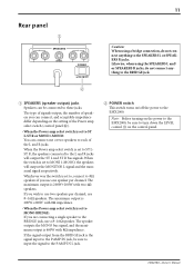
... speakers per channel. EMX2000-Owner's Manual The maximum output is 200W+200W with 8Ω impedance. Whichever way the switch is set to ST L-ST R or MONI 1-MONO: You can be sure to input the signal to the P.AMP IN L jack. 2 POWER switch This switch turns on/off the power to turn down the LEVEL control U on the setting of the L and R jacks. 11 Rear panel 1 SPEAKERS R L 2 1 BRIDGE 2 1 POWER ON OFF 2 Caution: When using the SPEAKERS L and/ or SPEAKERS R jacks, do not connect...
... speakers per channel. EMX2000-Owner's Manual The maximum output is 200W+200W with 8Ω impedance. Whichever way the switch is set to ST L-ST R or MONI 1-MONO: You can be sure to input the signal to the P.AMP IN L jack. 2 POWER switch This switch turns on/off the power to turn down the LEVEL control U on the setting of the L and R jacks. 11 Rear panel 1 SPEAKERS R L 2 1 BRIDGE 2 1 POWER ON OFF 2 Caution: When using the SPEAKERS L and/ or SPEAKERS R jacks, do not connect...

Owner's Manual
Page 13
... L Connecting a single speaker to the BRIDGE jack SPEAKERS R L 2 1 BRIDGE 2 1 2 1 BRIDGE 2 1 2 1 BRIDGE 2 1 4Ω~8Ω Main speaker 4Ω~8Ω Main/monitor speaker 8Ω~16Ω Main speakers 8Ω~16Ω Main/monitor speakers Connecting input/output equipment Microphone Foot switch CD player Cassette recorder 8Ω~16Ω Main speaker Main speakers MIC LINE INS I/O 1 MIC LINE INS I/O 2 MIC LINE INS I/O 3 INPUT MIC MIC MIC LINE INS I/O 4 LINE LINE 0dB INSERT I/O 5 OUT IN 6 MIC LINE 7 MIC 9 L B LINE 8 10 R B 9 L (MONO...
... L Connecting a single speaker to the BRIDGE jack SPEAKERS R L 2 1 BRIDGE 2 1 2 1 BRIDGE 2 1 2 1 BRIDGE 2 1 4Ω~8Ω Main speaker 4Ω~8Ω Main/monitor speaker 8Ω~16Ω Main speakers 8Ω~16Ω Main/monitor speakers Connecting input/output equipment Microphone Foot switch CD player Cassette recorder 8Ω~16Ω Main speaker Main speakers MIC LINE INS I/O 1 MIC LINE INS I/O 2 MIC LINE INS I/O 3 INPUT MIC MIC MIC LINE INS I/O 4 LINE LINE 0dB INSERT I/O 5 OUT IN 6 MIC LINE 7 MIC 9 L B LINE 8 10 R B 9 L (MONO...
Owner's Manual
Page 14
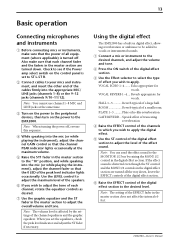
... control panel is affected by raising the MONI 1/2 control in the master section does not affect the internal effect. Note: You cannot use channel 1~8 MIC and LINE jacks at the maximum volume. 5 Raise the ST1 fader in digital effect, allowing reverberation or ambiance to be added to vocals or instrumental sounds. 1 Connect a mic or instrument to the desired channels, and adjust the volume and tone. 2 Press the ON switch of the digital effect section. 3 Use...
... control panel is affected by raising the MONI 1/2 control in the master section does not affect the internal effect. Note: You cannot use channel 1~8 MIC and LINE jacks at the maximum volume. 5 Raise the ST1 fader in digital effect, allowing reverberation or ambiance to be added to vocals or instrumental sounds. 1 Connect a mic or instrument to the desired channels, and adjust the volume and tone. 2 Press the ON switch of the digital effect section. 3 Use...
Owner's Manual
Page 15
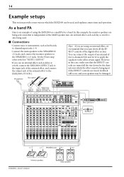
... connect the monitor speakers to the EMX2000's ST SUB 1. s Connections • Connect mics or instruments, such as delay or reverb is being input. However in which the effect sound is also being used , and explains connections and operation. If the EFFECT controls are being sent a mix that is an example of using an external effect, we recommend that the EFFECT controls are turned all the way down all the EFFECT controls of the MAIN speaker mix. Set the Power amp select switch to "MONI 1-MONO...
... connect the monitor speakers to the EMX2000's ST SUB 1. s Connections • Connect mics or instruments, such as delay or reverb is being input. However in which the effect sound is also being used , and explains connections and operation. If the EFFECT controls are being sent a mix that is an example of using an external effect, we recommend that the EFFECT controls are turned all the way down all the EFFECT controls of the MAIN speaker mix. Set the Power amp select switch to "MONI 1-MONO...
Owner's Manual
Page 16
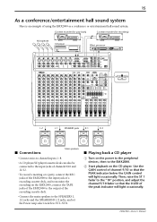
... deck. • Connect the main speakers to the SPEAKERS L 1/2 jacks and the SPEAKERS R 1/2 jacks, and set the Power amp select switch to the EMX2000. 2 Start playback on the EMX2000, connect the TAPE jacks of the EMX2000 to the output of the peak indicator will light occasionally. Cassette recorder (for paly back) Cassette recorder (for recording) Microphone CD player Effect processor 88 MIC LINE INS I/O 1 MIC LINE INS I/O 2 MIC LINE INS I/O 3 INPUT MIC MIC MIC LINE INS I/O 4 LINE LINE 0dB INSERT I/O 5 OUT IN 6 MIC LINE 7 MIC 9 L B LINE 8 10 R B 9 L (MONO) A 10...
... deck. • Connect the main speakers to the SPEAKERS L 1/2 jacks and the SPEAKERS R 1/2 jacks, and set the Power amp select switch to the EMX2000. 2 Start playback on the EMX2000, connect the TAPE jacks of the EMX2000 to the output of the peak indicator will light occasionally. Cassette recorder (for paly back) Cassette recorder (for recording) Microphone CD player Effect processor 88 MIC LINE INS I/O 1 MIC LINE INS I/O 2 MIC LINE INS I/O 3 INPUT MIC MIC MIC LINE INS I/O 4 LINE LINE 0dB INSERT I/O 5 OUT IN 6 MIC LINE 7 MIC 9 L B LINE 8 10 R B 9 L (MONO) A 10...

Owner's Manual
Page 17
... 2 EFFECT ST 1 MONO ST L MONI 1 ST R MONO MONO BRIDGE Power AMP Subwoofer L 1/2 SPEAKERS jacks R 1/2 EMX2000-Owner's Manual Main speakers 16 s Sending an independent mix to the monitor speakers 1 Set the MONI 1 or MONI 2 fader to the "10" position. 2 Raise the MONI 1 or MONI 2 controls for the channels to adjust the level of each channel. In this case, refer to the diagram on page 13 for connection information and follow the steps below. 1 Set the EFFECT fader of the master section...
... 2 EFFECT ST 1 MONO ST L MONI 1 ST R MONO MONO BRIDGE Power AMP Subwoofer L 1/2 SPEAKERS jacks R 1/2 EMX2000-Owner's Manual Main speakers 16 s Sending an independent mix to the monitor speakers 1 Set the MONI 1 or MONI 2 fader to the "10" position. 2 Raise the MONI 1 or MONI 2 controls for the channels to adjust the level of each channel. In this case, refer to the diagram on page 13 for connection information and follow the steps below. 1 Set the EFFECT fader of the master section...
Owner's Manual
Page 18
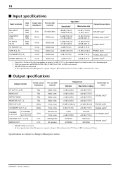
... input noise -63 dB residual output noise (SPEAKER OUT) -95 dB residual output noise (ST OUT, MONO OUT, EFFECT SEND, MONITOR OUT) -87 dB (ST OUT, MONO OUT) ST master/MONO master fader at maximum level and all channel level controls (EFFECT SEND, MONITOR OUT) at minimum. Comp. : THD≥0.5% Lit when THD≥0.5% 7 bands (125, 250, 500, 1k, 2k, 4k, 8k Hz), ±12 dB Maximum 16 programs Digital effect mute: on/off +48 V is supplied to output...
... input noise -63 dB residual output noise (SPEAKER OUT) -95 dB residual output noise (ST OUT, MONO OUT, EFFECT SEND, MONITOR OUT) -87 dB (ST OUT, MONO OUT) ST master/MONO master fader at maximum level and all channel level controls (EFFECT SEND, MONITOR OUT) at minimum. Comp. : THD≥0.5% Lit when THD≥0.5% 7 bands (125, 250, 500, 1k, 2k, 4k, 8k Hz), ±12 dB Maximum 16 programs Digital effect mute: on/off +48 V is supplied to output...
Owner's Manual
Page 19
... +20 dB (7.75 V) ST PHONE JACK1 SPEAKER OUT 1, 2 (L/R) BRIDGE OUT 0.1Ω 0.1Ω 4/8Ω Speaker 8Ω Speaker 200 W/4Ω 400 W/8Ω 200 W/4Ω 400 W/8Ω PHONE JACK1 1. OUT for PHONES for C. EMX2000-Owner's Manual before cliping Connectors on mixer MIC INPUT (1-8) MAX MIN LINE INPUT (1-8) MAX MIN ST INPUT (9-12) MAX MIN ST SUB IN (1, 2) TAPE IN (L, R) CH INSERT IN (1-4) 5 kΩ 50 kΩ 10 kΩ...
... +20 dB (7.75 V) ST PHONE JACK1 SPEAKER OUT 1, 2 (L/R) BRIDGE OUT 0.1Ω 0.1Ω 4/8Ω Speaker 8Ω Speaker 200 W/4Ω 400 W/8Ω 200 W/4Ω 400 W/8Ω PHONE JACK1 1. OUT for PHONES for C. EMX2000-Owner's Manual before cliping Connectors on mixer MIC INPUT (1-8) MAX MIN LINE INPUT (1-8) MAX MIN ST INPUT (9-12) MAX MIN ST SUB IN (1, 2) TAPE IN (L, R) CH INSERT IN (1-4) 5 kΩ 50 kΩ 10 kΩ...

Owner's Manual
Page 21
20 Block/Level Diagram ST EFFECT MONITOR AFL/PFL GAIN LOW MID HIGH 125 250 4k 8k MIC INPUT 1-4 LINE MIC INPUT 5-8 LINE 9L,11L (MONO) A 10R,12R INPUT 9/10 11/12 9L,11L B 10R,12R PHANTOM +48V PEAK PAD HA 3 Band EQ GAIN LOW MID HIGH INS I/O PEAK PAD HA 3 Band EQ GAIN LOW MID HIGH HA A/B HA 3 Band EQ 3 Band EQ PEAK L (MONO) ST SUB 1,2 R PAD PAD L TAPE R ON dB +40...
20 Block/Level Diagram ST EFFECT MONITOR AFL/PFL GAIN LOW MID HIGH 125 250 4k 8k MIC INPUT 1-4 LINE MIC INPUT 5-8 LINE 9L,11L (MONO) A 10R,12R INPUT 9/10 11/12 9L,11L B 10R,12R PHANTOM +48V PEAK PAD HA 3 Band EQ GAIN LOW MID HIGH INS I/O PEAK PAD HA 3 Band EQ GAIN LOW MID HIGH HA A/B HA 3 Band EQ 3 Band EQ PEAK L (MONO) ST SUB 1,2 R PAD PAD L TAPE R ON dB +40...


