
Owner's Manual
Page 3
... SPEAKER OUTPUT LEVELS 22 Before You Begin 22 Using the Test Tone (TEST DOLBY SUR 22 BASIC OPERATION BASIC PLAYBACK 24 Input Modes and Indications 26 Selecting a Sound Field Program 28 Normal Stereo Reproduction 29 BASIC RECORDING 30 ADVANCED OPERATION SET MENU 31 Adjusting the Items on the SET MENU 31 1 SPEAKER SET (speaker mode settings 32 2 L/R BALANCE (balance of the Numeric Buttons 7 Using the Remote Control 8 Front Panel Display 9 Rear Panel 10 PREPARATION SPEAKER SETUP 11 Speakers to the Factory-set 36 7 DTS SET (DTS LFE level 36 8 SP DELAY TIME 37 9 DISPLAY SET...
... SPEAKER OUTPUT LEVELS 22 Before You Begin 22 Using the Test Tone (TEST DOLBY SUR 22 BASIC OPERATION BASIC PLAYBACK 24 Input Modes and Indications 26 Selecting a Sound Field Program 28 Normal Stereo Reproduction 29 BASIC RECORDING 30 ADVANCED OPERATION SET MENU 31 Adjusting the Items on the SET MENU 31 1 SPEAKER SET (speaker mode settings 32 2 L/R BALANCE (balance of the Numeric Buttons 7 Using the Remote Control 8 Front Panel Display 9 Rear Panel 10 PREPARATION SPEAKER SETUP 11 Speakers to the Factory-set 36 7 DTS SET (DTS LFE level 36 8 SP DELAY TIME 37 9 DISPLAY SET...
Owner's Manual
Page 4
... Speaker Balance Adjustment N 6-Channel External Decoder Input for Other Future Formats N BASS EXTENSION Button for Reinforcing Bass Response N On Screen Display Function Helpful in Controlling This Unit N S Video Signal Input/Output Capability N Component Video Input/Output Capability N Optical and Coaxial Digital Audio Signal Jacks N Sleep Timer N Remote Control with Preset Manufacturer Codes • y indicates a tip for your operation. • Some operations can be performed by using either the buttons on the main unit or on the remote control is given in parentheses in this manual...
... Speaker Balance Adjustment N 6-Channel External Decoder Input for Other Future Formats N BASS EXTENSION Button for Reinforcing Bass Response N On Screen Display Function Helpful in Controlling This Unit N S Video Signal Input/Output Capability N Component Video Input/Output Capability N Optical and Coaxial Digital Audio Signal Jacks N Sleep Timer N Remote Control with Preset Manufacturer Codes • y indicates a tip for your operation. • Some operations can be performed by using either the buttons on the main unit or on the remote control is given in parentheses in this manual...
Owner's Manual
Page 6
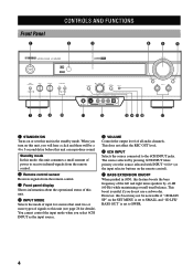
... types of signals to 5-second delay before this feature boosts the bass frequency of all audio channels. This boost is set to the 6CH INPUT jacks. You cannot control the input mode when you do not use a subwoofer. Front Panel 1 CONTROLS AND FUNCTIONS 2 3 4 5 6 STANDBY /ON D I G I TA L SURROUND BASS EXTENSION BASS TREBLE ON OFF -+ -+ SPEAKERS A B ON OFF 78 9 0 D I G I TA L VOLUME SET MENU DSP PROGRAM EFFECT PHONES S VIDEO - VIDEO + L AUDIO R OPTICAL INPUT MODE INPUT 6CH INPUT SILENT q VIDEO AUX w erty u 1 STANDBY/ON Turns on the SET MENU is set to...
... types of signals to 5-second delay before this feature boosts the bass frequency of all audio channels. This boost is set to the 6CH INPUT jacks. You cannot control the input mode when you do not use a subwoofer. Front Panel 1 CONTROLS AND FUNCTIONS 2 3 4 5 6 STANDBY /ON D I G I TA L SURROUND BASS EXTENSION BASS TREBLE ON OFF -+ -+ SPEAKERS A B ON OFF 78 9 0 D I G I TA L VOLUME SET MENU DSP PROGRAM EFFECT PHONES S VIDEO - VIDEO + L AUDIO R OPTICAL INPUT MODE INPUT 6CH INPUT SILENT q VIDEO AUX w erty u 1 STANDBY/ON Turns on the SET MENU is set to...

Owner's Manual
Page 7
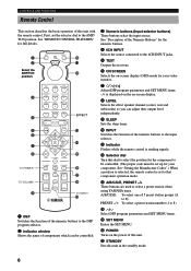
... reproduce source signals from a portable external source such as the input source. t DSP PROGRAM Switches the function of the multi jog knob for the left and right main speakers. 0 SPEAKERS A/B When pushed in (ON), these buttons turn off . If you connect headphones, no signals are also output to or watch. When Dolby Digital or DTS signals are directed to decrease the low-frequency response. 9 TREBLE Adjusts the high-frequency response for selecting DSP program. models only) • When you turn on the set...
... reproduce source signals from a portable external source such as the input source. t DSP PROGRAM Switches the function of the multi jog knob for the left and right main speakers. 0 SPEAKERS A/B When pushed in (ON), these buttons turn off . If you connect headphones, no signals are also output to or watch. When Dolby Digital or DTS signals are directed to decrease the low-frequency response. 9 TREBLE Adjusts the high-frequency response for selecting DSP program. models only) • When you turn on the set...
Owner's Manual
Page 8
q Indicator Flashes while the remote control is set to the AMP/ TUN position. y POWER Turns on -screen display. 8 LEVEL Selects the effect speaker channel (center, rear and subwoofer) so you can be set the selector dial to that component operation mode. See "Description of the Numeric Buttons" for the numeric buttons. 4 6CH INPUT Selects the source connected to the 6CH INPUT jacks. 5 TEST Outputs the test tone. 6 ON SCREEN Selects the on-screen display (OSD) mode for full details. 1 0 2 q Select the AMP/TUN w position. 3 4 5 6 7 8 TV POWER TV VOLUME 9 EFFECT A/B/C/D/E ...
q Indicator Flashes while the remote control is set to the AMP/ TUN position. y POWER Turns on -screen display. 8 LEVEL Selects the effect speaker channel (center, rear and subwoofer) so you can be set the selector dial to that component operation mode. See "Description of the Numeric Buttons" for the numeric buttons. 4 6CH INPUT Selects the source connected to the 6CH INPUT jacks. 5 TEST Outputs the test tone. 6 ON SCREEN Selects the on-screen display (OSD) mode for full details. 1 0 2 q Select the AMP/TUN w position. 3 4 5 6 7 8 TV POWER TV VOLUME 9 EFFECT A/B/C/D/E ...

Owner's Manual
Page 11
... the type of the selected DSP program lights up when the ENTERTAINMENT, MOVIE THEATER 1, MOVIE THEATER 2 or q/DTS SURROUND DSP program is selected. 9 Multi-information display Shows the current DSP program name and other information when adjusting or changing settings. 0 VOLUME level indicator Indicates the volume level. INTRODUCTION PREPARATION Front Panel Display CONTROLS AND FUNCTIONS 1 23 4 VIRTUAL DIGITAL PRO LOGIC DSP V-AUX VCR2/DVR VCR 1 D-TV/CBL DOLBY DIGITAL MOVIE THEATER 1 2 PRO LOGIC DTS ENTERTAINMENT SP PCM AB DVD MD/CD-R TUNER CD PHONO SLEEP dmBs VOLUME 56 7 8 9 0q...
... the type of the selected DSP program lights up when the ENTERTAINMENT, MOVIE THEATER 1, MOVIE THEATER 2 or q/DTS SURROUND DSP program is selected. 9 Multi-information display Shows the current DSP program name and other information when adjusting or changing settings. 0 VOLUME level indicator Indicates the volume level. INTRODUCTION PREPARATION Front Panel Display CONTROLS AND FUNCTIONS 1 23 4 VIRTUAL DIGITAL PRO LOGIC DSP V-AUX VCR2/DVR VCR 1 D-TV/CBL DOLBY DIGITAL MOVIE THEATER 1 2 PRO LOGIC DTS ENTERTAINMENT SP PCM AB DVD MD/CD-R TUNER CD PHONO SLEEP dmBs VOLUME 56 7 8 9 0q...

Owner's Manual
Page 12
...for connection information. 7 OUTPUT jacks (Europe and U.K. Set this unit in the standby mode before you change the setting of this switch to match the amplifier output to your speaker impedance. CONTROLS AND FUNCTIONS Rear Panel 1 23 4 5 6 7 89 DIGITAL INPUT CD COAXIAL OPTICAL D-TV/CBL DVD GND TUNER L R 6CH INPUT MAIN SURROUND CENTER L L MD/CD-R DVD D-TV/CBL R+ A MAIN MONITOR OUT Y PB/CB PR/CR COMPONENT VIDEO B DVD D-TV/CBL IN VCR 1OUT IN V/DCVRR2OUT MONITOR OUT VIDEO CENTER + S VIDEO OPTICAL MD/CD-R R L R SUB WOOFER VIDEO SIGNAL DIGITAL OUTPUT R PHONO CD...
...for connection information. 7 OUTPUT jacks (Europe and U.K. Set this unit in the standby mode before you change the setting of this switch to match the amplifier output to your speaker impedance. CONTROLS AND FUNCTIONS Rear Panel 1 23 4 5 6 7 89 DIGITAL INPUT CD COAXIAL OPTICAL D-TV/CBL DVD GND TUNER L R 6CH INPUT MAIN SURROUND CENTER L L MD/CD-R DVD D-TV/CBL R+ A MAIN MONITOR OUT Y PB/CB PR/CR COMPONENT VIDEO B DVD D-TV/CBL IN VCR 1OUT IN V/DCVRR2OUT MONITOR OUT VIDEO CENTER + S VIDEO OPTICAL MD/CD-R R L R SUB WOOFER VIDEO SIGNAL DIGITAL OUTPUT R PHONO CD...

Owner's Manual
Page 19
...the subwoofer volume according to the operating instructions for the subwoofer. (Fine adjustment is decoded are also directed if they are directed to this jack. (The cut-off frequency of "1 SPEAKER SET", "6 DOLBY D. INTRODUCTION Main speakers A CONNECTIONS Main speakers B Right Left Right Left (Europe model) D R+ /CBL A TOR T OMPONENT VIDEO MONITOR OUT MAIN B VIDEO CENTER + S VIDEO R+ SUB WOOFER OUTPUT REAR (SURROUND) SPEAKERS - - - - - +L MAINS AC OUTLETS OUTPUT R MAIN R REAR (SURROUND) + L CENTER L L IMPEDANCE SELECTOR SET BEFORE POWER ON SWITCHED 100W...
...the subwoofer volume according to the operating instructions for the subwoofer. (Fine adjustment is decoded are also directed if they are directed to this jack. (The cut-off frequency of "1 SPEAKER SET", "6 DOLBY D. INTRODUCTION Main speakers A CONNECTIONS Main speakers B Right Left Right Left (Europe model) D R+ /CBL A TOR T OMPONENT VIDEO MONITOR OUT MAIN B VIDEO CENTER + S VIDEO R+ SUB WOOFER OUTPUT REAR (SURROUND) SPEAKERS - - - - - +L MAINS AC OUTLETS OUTPUT R MAIN R REAR (SURROUND) + L CENTER L L IMPEDANCE SELECTOR SET BEFORE POWER ON SWITCHED 100W...

Owner's Manual
Page 21
... OUTLETS IMPEDANCE SELECTOR SET BEFORE POWER ON SWITCHED 100W MAX. If so, slide the switch to turn on when STANDBY/ON (or POWER) is pressed, the IMPEDANCE SELECTOR switch may be 6 Ω or higher. VOLTAGE SELECTOR (General model) AC OUTLETS SWITCHED 100W MAX. model 1 OUTLET Use these outlets to connect the power cords only from your audio/video components to the AC OUTLET(S) is in your local main voltage BEFORE plugging...
... OUTLETS IMPEDANCE SELECTOR SET BEFORE POWER ON SWITCHED 100W MAX. If so, slide the switch to turn on when STANDBY/ON (or POWER) is pressed, the IMPEDANCE SELECTOR switch may be 6 Ω or higher. VOLTAGE SELECTOR (General model) AC OUTLETS SWITCHED 100W MAX. model 1 OUTLET Use these outlets to connect the power cords only from your audio/video components to the AC OUTLET(S) is in your local main voltage BEFORE plugging...

Owner's Manual
Page 22
... test tone display appear regardless of the main volume for a few seconds and then switch to show the current DSP program. 2 Press ON SCREEN on both the S VIDEO OUT and VIDEO OUT jacks. If no changes to turn on the power, the video monitor and front panel display show the level of the OSD mode. 20 Make sure to connect your video monitor is carried only on the SET MENU. OSD Modes You can change the display mode. ON-SCREEN DISPLAY...
... test tone display appear regardless of the main volume for a few seconds and then switch to show the current DSP program. 2 Press ON SCREEN on both the S VIDEO OUT and VIDEO OUT jacks. If no changes to turn on the power, the video monitor and front panel display show the level of the OSD mode. 20 Make sure to connect your video monitor is carried only on the SET MENU. OSD Modes You can change the display mode. ON-SCREEN DISPLAY...

Owner's Manual
Page 25
... state of the test tone output is convenient for the center and rear speakers again. 5 Press j / i repeatedly to adjust the output level of the currently selected speaker so that it is complete, press TEST. This is also shown on the monitor by pressing d. (Pressing u changes the selection in the standby mode and check the speaker connections. 4 Press LEVEL repeatedly to select the speaker to be heard, turn down the volume, set "1E MAIN LEVEL" on page...
... state of the test tone output is convenient for the center and rear speakers again. 5 Press j / i repeatedly to adjust the output level of the currently selected speaker so that it is complete, press TEST. This is also shown on the monitor by pressing d. (Pressing u changes the selection in the standby mode and check the speaker connections. 4 Press LEVEL repeatedly to select the speaker to be heard, turn down the volume, set "1E MAIN LEVEL" on page...
Owner's Manual
Page 27
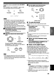
... the operation instructions for digital output. The following when a 96-kHz sampling digital signal is turned off "6CH INPUT" from the subwoofer. 3. BASS EXTENSION BASS TREBLE ON OFF -+ Front panel -+ Note • If the component connected to the VCR 1 OUT, VCR 2/DVR OUT and MD/CD-R OUT jacks is input to this unit in the standby mode. I Notes on the video monitor. 6CH INPUT or Front panel Remote control BASIC PLAYBACK 6 Use the digital sound field processor. To select a source connected...
... the operation instructions for digital output. The following when a 96-kHz sampling digital signal is turned off "6CH INPUT" from the subwoofer. 3. BASS EXTENSION BASS TREBLE ON OFF -+ Front panel -+ Note • If the component connected to the VCR 1 OUT, VCR 2/DVR OUT and MD/CD-R OUT jacks is input to this unit in the standby mode. I Notes on the video monitor. 6CH INPUT or Front panel Remote control BASIC PLAYBACK 6 Use the digital sound field processor. To select a source connected...

Owner's Manual
Page 34
... selected as the input source, level adjustments in the standby mode, the power cord is disconnected from the SET MENU. 1 SPEAKER SET (speaker mode settings) Use this unit, level adjustments in items 1B and 1D are possible, but those in items 1A,1C and 1E are directed to enter the setup mode of the SET MENU you set this unit is directed to the center speaker. 1A CENTER SP or y • When operating through the front panel, turn the multi jog knob to change...
... selected as the input source, level adjustments in the standby mode, the power cord is disconnected from the SET MENU. 1 SPEAKER SET (speaker mode settings) Use this unit, level adjustments in items 1B and 1D are possible, but those in items 1A,1C and 1E are directed to enter the setup mode of the SET MENU you set this unit is directed to the center speaker. 1A CENTER SP or y • When operating through the front panel, turn the multi jog knob to change...

Owner's Manual
Page 38
... Dialog level Output level Output level 1.0 0.0 L-LEVEL BST Input level Input level Note • When you select MIN, the sound output may be faint because some Dolby Digital signals are not compatible with the minimum-level dynamic range. The LFE signal carries the low-frequency special effect sound which is most suitable for listening to adjust the output level of the LFE (low-frequency effect) channel when playing back a Dolby Digital signal. I LFE LEVEL Use this unit decodes Dolby Digital signals. Control range (dB): -10 to +10 Initial setting: 0 dB 7 DTS SET LFE LEVEL...
... Dialog level Output level Output level 1.0 0.0 L-LEVEL BST Input level Input level Note • When you select MIN, the sound output may be faint because some Dolby Digital signals are not compatible with the minimum-level dynamic range. The LFE signal carries the low-frequency special effect sound which is most suitable for listening to adjust the output level of the LFE (low-frequency effect) channel when playing back a Dolby Digital signal. I LFE LEVEL Use this unit decodes Dolby Digital signals. Control range (dB): -10 to +10 Initial setting: 0 dB 7 DTS SET LFE LEVEL...

Owner's Manual
Page 39
... video signal input. Choices: ON, OFF Initial setting: OFF 10 MEMORY GUARD OFF ON -/+ : Select / : Exit Select ON to protect the following features: • DSP program parameters • All SET MENU items • Center, rear speakers and subwoofer levels • The on the screen including the onscreen display if OFF is selected. Control range: +5 (downward) to -5 (upward) Initial setting: 0 Press i to lower the position of the front panel display. Control range (ms): 0 to 5 Initial setting: 0 ms 8 SP DELAY TIME CENTER...
... video signal input. Choices: ON, OFF Initial setting: OFF 10 MEMORY GUARD OFF ON -/+ : Select / : Exit Select ON to protect the following features: • DSP program parameters • All SET MENU items • Center, rear speakers and subwoofer levels • The on the screen including the onscreen display if OFF is selected. Control range: +5 (downward) to -5 (upward) Initial setting: 0 Press i to lower the position of the front panel display. Control range (ms): 0 to 5 Initial setting: 0 ms 8 SP DELAY TIME CENTER...
Owner's Manual
Page 48
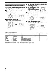
... DVD/LD CD TAPE/MD Component TV Satellite tuner VCR DVD player CD player MD recorder Code 0101 0006 0002 0008 (YAMAHA DVD player) 0005 (YAMAHA CD player) 0024 (YAMAHA MD recorder) Set component We recommend that you have set . Make sure that the indicator flashes twice. 3 Enter the code number "0000". The indicator flashes twice. 2 Enter the code number "9990". REMOTE CONTROL FEATURES Returning to the Factory Setting I To return to the factory setting. 2 Press j / i at the same time...
... DVD/LD CD TAPE/MD Component TV Satellite tuner VCR DVD player CD player MD recorder Code 0101 0006 0002 0008 (YAMAHA DVD player) 0005 (YAMAHA CD player) 0024 (YAMAHA MD recorder) Set component We recommend that you have set . Make sure that the indicator flashes twice. 3 Enter the code number "0000". The indicator flashes twice. 2 Enter the code number "9990". REMOTE CONTROL FEATURES Returning to the Factory Setting I To return to the factory setting. 2 Press j / i at the same time...

Owner's Manual
Page 57
... SET MENU is pressed, or enters in the standby mode, disconnect the power cord and contact the nearest authorized YAMAHA dealer or service center. The speaker connections are experiencing is input to be defective. The main speakers to this unit can be defective. 12 - 17 ADVANCED OPERATION ADDITIONAL INFORMATION APPENDIX English 55 Connect the cables properly. The protection circuit has been activated because of jack (between composites, S-VIDEOs, or components...
... SET MENU is pressed, or enters in the standby mode, disconnect the power cord and contact the nearest authorized YAMAHA dealer or service center. The speaker connections are experiencing is input to be defective. The main speakers to this unit can be defective. 12 - 17 ADVANCED OPERATION ADDITIONAL INFORMATION APPENDIX English 55 Connect the cables properly. The protection circuit has been activated because of jack (between composites, S-VIDEOs, or components...

Owner's Manual
Page 58
... a Dolby Digital or DTS signal is set to the GND terminal of your speaker configuration. The output mode for each speaker (main, center or rear) on a turntable with the program 9. Firmly connect the audio plugs. Connect the grounding cord of this unit. No sound from the effect speakers. A Dolby Surround, Dolby Digital or DTS decoding DSP program is low while playing a record. The output level of the center speaker is being input to turn it on the size of the rear speakers. "1A CENTER SP" on the SET MENU...
... a Dolby Digital or DTS signal is set to the GND terminal of your speaker configuration. The output mode for each speaker (main, center or rear) on a turntable with the program 9. Firmly connect the audio plugs. Connect the grounding cord of this unit. No sound from the effect speakers. A Dolby Surround, Dolby Digital or DTS decoding DSP program is low while playing a record. The output level of the center speaker is being input to turn it on the size of the rear speakers. "1A CENTER SP" on the SET MENU...

Owner's Manual
Page 64
... PHONO jack 12 Playing 24 Power supply cords 19 R Rear panel 10 Recording 30 Remote control Basic operation 6 Batteries 3 Operation range 8 Setup codes 45 S Sampling frequency 25, 61 Selector dial 6, 40 SET MENU 31 SILENT CINEMA 29, 60 Sleep timer 39 Sound field 50 SP DELAY TIME (SET MENU 37 Speaker Output balance (test tone 22 Output levels (LEVEL mode 38 Output mode (SET MENU 21 Placement 11 SPEAKER SET (SET MENU) CENTER SP 32 LFE/BASS OUT 34 MAIN LEVEL 34 MAIN SP 33 REAR L/R SP 33 Stereo reproduction 29 Subwoofer 17 S VIDEO 61 T TAPE/MD position 42 Test tone...
... PHONO jack 12 Playing 24 Power supply cords 19 R Rear panel 10 Recording 30 Remote control Basic operation 6 Batteries 3 Operation range 8 Setup codes 45 S Sampling frequency 25, 61 Selector dial 6, 40 SET MENU 31 SILENT CINEMA 29, 60 Sleep timer 39 Sound field 50 SP DELAY TIME (SET MENU 37 Speaker Output balance (test tone 22 Output levels (LEVEL mode 38 Output mode (SET MENU 21 Placement 11 SPEAKER SET (SET MENU) CENTER SP 32 LFE/BASS OUT 34 MAIN LEVEL 34 MAIN SP 33 REAR L/R SP 33 Stereo reproduction 29 Subwoofer 17 S VIDEO 61 T TAPE/MD position 42 Test tone...
Owner's Manual
Page 71
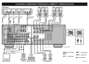
... a digital 5.1-channel source) DVD player OPTICAL AUDIO OUT L R S VIDEO OUT VIDEO OUT COMPONENT VIDEO OUT Main speakers A Main speakers B OPTICAL OUT AUDIO S VIDEO VIDEO OUT OUT OUT O LR V S R COMPONENT VIDEO OUT LR L DIGITAL INPUT CD SIGNAL GND TUNER L DVD D-TV/CBL R+ A COAXIAL OPTICAL D-TV/CBL DVD R 6CH INPUT MAIN SURROUND CENTER L L MD/CD-R MAIN MONITOR OUT Y PB/CB PR/CR COMPONENT VIDEO B DVD D-TV/CBL IN VCR 1OUT IN V/DCVRR2OUT MONITOR OUT VIDEO CENTER + S VIDEO OPTICAL MD/CD-R R L R SUB WOOFER VIDEO SIGNAL DIGITAL OUTPUT R PHONO CD IN(PLAY...
... a digital 5.1-channel source) DVD player OPTICAL AUDIO OUT L R S VIDEO OUT VIDEO OUT COMPONENT VIDEO OUT Main speakers A Main speakers B OPTICAL OUT AUDIO S VIDEO VIDEO OUT OUT OUT O LR V S R COMPONENT VIDEO OUT LR L DIGITAL INPUT CD SIGNAL GND TUNER L DVD D-TV/CBL R+ A COAXIAL OPTICAL D-TV/CBL DVD R 6CH INPUT MAIN SURROUND CENTER L L MD/CD-R MAIN MONITOR OUT Y PB/CB PR/CR COMPONENT VIDEO B DVD D-TV/CBL IN VCR 1OUT IN V/DCVRR2OUT MONITOR OUT VIDEO CENTER + S VIDEO OPTICAL MD/CD-R R L R SUB WOOFER VIDEO SIGNAL DIGITAL OUTPUT R PHONO CD IN(PLAY...


