
AVS-700 OWNERS MANUAL
Page 1
... Owner's Manual in the space below. IMPORTANT Please record the serial number of the unit. Model: AVS-100 Serial No.: The serial number is located on 13 Troubleshooting 14 Specifications Back cover -, - VS 700 Natural Sound AV Selector i 10 Audio/5 Video Inputs, Including 4 S Video Terminals 4 Audio/2 Video Rec Out Terminals Ideally suited or use with the DSP-A700 Digital Sound Field Processing Amplifier -20 dB Audio Muting Wireless Remote Control Transmitter Thahk you fo sin the YAMAHA AVS 700 AV...
... Owner's Manual in the space below. IMPORTANT Please record the serial number of the unit. Model: AVS-100 Serial No.: The serial number is located on 13 Troubleshooting 14 Specifications Back cover -, - VS 700 Natural Sound AV Selector i 10 Audio/5 Video Inputs, Including 4 S Video Terminals 4 Audio/2 Video Rec Out Terminals Ideally suited or use with the DSP-A700 Digital Sound Field Processing Amplifier -20 dB Audio Muting Wireless Remote Control Transmitter Thahk you fo sin the YAMAHA AVS 700 AV...
AVS-700 OWNERS MANUAL
Page 2
..., is operated. 2 Retain Instructions - The appliance should be used near swimming pool, etc. 6 Carts and Stands - The power cord of the appliance should be followed. 5 Water and Moisture - NO USER-SERVICEABLE PARTS INSIDE. WARNING...time. 14 Object and Liquid Entry - For example, the appliance shouk not be moved with arrowhead symbol, within the product's enclosure that may block the ventilation openings: or placed in built-in installation, such as a bookcase or cabinet th may impede the flow of the type described in the literature accompanying the appliance. Power...
..., is operated. 2 Retain Instructions - The appliance should be used near swimming pool, etc. 6 Carts and Stands - The power cord of the appliance should be followed. 5 Water and Moisture - NO USER-SERVICEABLE PARTS INSIDE. WARNING...time. 14 Object and Liquid Entry - For example, the appliance shouk not be moved with arrowhead symbol, within the product's enclosure that may block the ventilation openings: or placed in built-in installation, such as a bookcase or cabinet th may impede the flow of the type described in the literature accompanying the appliance. Power...
AVS-700 OWNERS MANUAL
Page 3
... not properly set the volume control of the amplifier to indicate your unit in performance; away from power lines. 15 Grounding or Polarization - Do not use force on common operating errors before you plug it is not defeated. 1. Always set , reset the switch to "-OO" or the attenuator of hum (transformers, motors.). CAUTION: READ THIS BEFORE OPERATING YOUR AVS-700 S 15 Damage Requiring Service - The precautions...
... not properly set the volume control of the amplifier to indicate your unit in performance; away from power lines. 15 Grounding or Polarization - Do not use force on common operating errors before you plug it is not defeated. 1. Always set , reset the switch to "-OO" or the attenuator of hum (transformers, motors.). CAUTION: READ THIS BEFORE OPERATING YOUR AVS-700 S 15 Damage Requiring Service - The precautions...
AVS-700 OWNERS MANUAL
Page 5
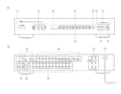
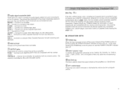
...MONITOR OUT. v.'"° urevErmao 1 SWITCHED CTS "-0UTPUT"'"'s 4\. • ® 0 ®'/C:17•)))\) f3 4 0 ) C) (C) (C) C) C)) SE #) ONO....MOND .....CO wr "631. %•1'',wTAPIr a''' r". 7APS7*°' 11911/TVwwL0 C, ''''" Rr " "" ' VOar -*u. LW REC CUT ON/OPP MUTING Ds 11 0 14 MOTE CONTROL... . vcor VCPS "'" O O . M0 xn MY, mum wan law ' - , © rhA .,..„ ..1O PS0 40 ,011800 ,186ii;\ ......-- /8)TV W ( .ee o VCPI _L....VCAS La-- ®© 0 IONIA NATURAL SOUND AV SELECTOR AVG-700 POWER AUX STANDBY „,..
...MONITOR OUT. v.'"° urevErmao 1 SWITCHED CTS "-0UTPUT"'"'s 4\. • ® 0 ®'/C:17•)))\) f3 4 0 ) C) (C) (C) C) C)) SE #) ONO....MOND .....CO wr "631. %•1'',wTAPIr a''' r". 7APS7*°' 11911/TVwwL0 C, ''''" Rr " "" ' VOar -*u. LW REC CUT ON/OPP MUTING Ds 11 0 14 MOTE CONTROL... . vcor VCPS "'" O O . M0 xn MY, mum wan law ' - , © rhA .,..„ ..1O PS0 40 ,011800 ,186ii;\ ......-- /8)TV W ( .ee o VCPI _L....VCAS La-- ®© 0 IONIA NATURAL SOUND AV SELECTOR AVG-700 POWER AUX STANDBY „,..
AVS-700 OWNERS MANUAL
Page 7
... 2, Laser Disc player/CD Video player, Television, Tape deck 2, Tape deck 1, Tuner, CD player or Turntable). When one of the remote control transmitter, the sound level will be recorded. To obtain a high resolution picture, connect S input connector on and the POWER STANDBY indicator goes off the power instead of any source, even while monitoring another. The REC OUT ON/OFF button Is used to select the source you wish to turn off the output of the source signal selected with...
... 2, Laser Disc player/CD Video player, Television, Tape deck 2, Tape deck 1, Tuner, CD player or Turntable). When one of the remote control transmitter, the sound level will be recorded. To obtain a high resolution picture, connect S input connector on and the POWER STANDBY indicator goes off the power instead of any source, even while monitoring another. The REC OUT ON/OFF button Is used to select the source you wish to turn off the output of the source signal selected with...
AVS-700 OWNERS MANUAL
Page 8
... YAMAHA components (with the REC OUT selector, the corresponding indicator lights. Connect to a Video Cassette Recorder for remote control of the S VIDEO connectors are used to an AC wall outlet. The power to th AV selector. Ell 0 REMOTE CONTROL cable connectors These connectors are connected at the same time, only the signals of each component. Connect to a tuner using the cable with this switch is pressed, the sound level is turned on a TV monitor. 7 VIDEO connectors With the S VIDEO connections...
... YAMAHA components (with the REC OUT selector, the corresponding indicator lights. Connect to a Video Cassette Recorder for remote control of the S VIDEO connectors are used to an AC wall outlet. The power to th AV selector. Ell 0 REMOTE CONTROL cable connectors These connectors are connected at the same time, only the signals of each component. Connect to a tuner using the cable with this switch is pressed, the sound level is turned on a TV monitor. 7 VIDEO connectors With the S VIDEO connections...
AVS-700 OWNERS MANUAL
Page 9
... volume control. Connect to the TUNER, CD, PHONO, TV, TAPE 2, TAPE 1, VCR 2, VCR 1, LD or AUX jacks of a program source. 8 O OUTPUT jacks These jacks are YAMAHA components designed for both recording and playback. 0 GND terminal Connect to the ground wire from your components to your YAMAHA dealer for information on which components are compatible with the DSP-A700 amplifier will directly operate any compatible YAMAHA CD, LD/CDV player, and some Tuners or Cassette Decks bearing the !gm mark. PHONO - Connect...
... volume control. Connect to the TUNER, CD, PHONO, TV, TAPE 2, TAPE 1, VCR 2, VCR 1, LD or AUX jacks of a program source. 8 O OUTPUT jacks These jacks are YAMAHA components designed for both recording and playback. 0 GND terminal Connect to the ground wire from your components to your YAMAHA dealer for information on which components are compatible with the DSP-A700 amplifier will directly operate any compatible YAMAHA CD, LD/CDV player, and some Tuners or Cassette Decks bearing the !gm mark. PHONO - Connect...
AVS-700 OWNERS MANUAL
Page 10
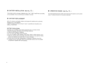
... that they are installed correctly. • BATTERY REPLACEMENT When the 'emote controllable distance decreases the batteries are exhaused. re When the remote control transmitter will not be within about 7 meters (23 feet) of time, remove the batteries and store them according to the illustration. BATTERY PRIECAUTIONS Incorrect use an old battery with new batteries. • OPERATION RANGE (See Fig...
... that they are installed correctly. • BATTERY REPLACEMENT When the 'emote controllable distance decreases the batteries are exhaused. re When the remote control transmitter will not be within about 7 meters (23 feet) of time, remove the batteries and store them according to the illustration. BATTERY PRIECAUTIONS Incorrect use an old battery with new batteries. • OPERATION RANGE (See Fig...
AVS-700 OWNERS MANUAL
Page 11
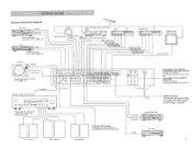
tuner with an Egge mark TV set Laser Vision Disc player or CD Video player VCR Video output jack Audio outpu jacks Video output jack 1 Audio output jacks Video output jackj Video input jack AuZio oulpplacks. , Audio input 1acWts Second VCR Video output jack Vidueooinout s • • sut ura16rac s Aucito input jacks TV/Monitor with video input jack i Video input jack Turntable OUTPUT Ground wire • Remote terminal for e. Power plugs for UK mod Handles up to 300 W Linked to the POWER switch of thit unit. El= 10 , CONNECTI9NS System Connection Diagram 5 gam a ...
tuner with an Egge mark TV set Laser Vision Disc player or CD Video player VCR Video output jack Audio outpu jacks Video output jack 1 Audio output jacks Video output jackj Video input jack AuZio oulpplacks. , Audio input 1acWts Second VCR Video output jack Vidueooinout s • • sut ura16rac s Aucito input jacks TV/Monitor with video input jack i Video input jack Turntable OUTPUT Ground wire • Remote terminal for e. Power plugs for UK mod Handles up to 300 W Linked to the POWER switch of thit unit. El= 10 , CONNECTI9NS System Connection Diagram 5 gam a ...
AVS-700 OWNERS MANUAL
Page 12
... volume control, connect the amplifier to the VARIABLE OUTPUT jacks of this connection, the remote control transmitter supplied wit] the DSP-A700 can control the tuner. * If your tuner bears the grp,kri mark, and it can be directly operated with the remote control transmitter supplied with the DSP-A700 can control those components as the remote control transmitter operates the player directly. When a cassette deck equipped with mini-plug. 11 • COMPACT DISC PLAYER Connect the output jacks of the compact disc player to the CD jacks...
... volume control, connect the amplifier to the VARIABLE OUTPUT jacks of this connection, the remote control transmitter supplied wit] the DSP-A700 can control the tuner. * If your tuner bears the grp,kri mark, and it can be directly operated with the remote control transmitter supplied with the DSP-A700 can control those components as the remote control transmitter operates the player directly. When a cassette deck equipped with mini-plug. 11 • COMPACT DISC PLAYER Connect the output jacks of the compact disc player to the CD jacks...
AVS-700 OWNERS MANUAL
Page 13
... VIDEO SOURCE If necessary, you can connect a third video input source, such as the audio portion of a second VCR to the VCR 2 AUDIO SIGNAL jacks. Note that has an S video connector is sent to your speakers through the amplifier. to the MONITOR OUT jack on the rear panel of this unit. Connect the audio output jacks of the VCR to the VCR 1 AUDIO SIGNAL jacks, and connect the audio output jacks of the signal is used , connect the S VIDEO connectors. With the S VIDEO connections...
... VIDEO SOURCE If necessary, you can connect a third video input source, such as the audio portion of a second VCR to the VCR 2 AUDIO SIGNAL jacks. Note that has an S video connector is sent to your speakers through the amplifier. to the MONITOR OUT jack on the rear panel of this unit. Connect the audio output jacks of the VCR to the VCR 1 AUDIO SIGNAL jacks, and connect the audio output jacks of the signal is used , connect the S VIDEO connectors. With the S VIDEO connections...
AVS-700 OWNERS MANUAL
Page 14
... with the INPUT SELECT( button. 4. Select the program source to both the MONITOR OUT S VIDEO connector and the MONITOR OUT pin jack. Press REC OUT ON/OFF button to the -20 dB level. For video sources, turn it constantly. Adjust the sound with the input/output cables. 4. This lets you can listen to turn the unit ON. 2. Connect the power cord of the unit connected to be recorded and set to VCR 1 (or VCR 2), signals are not...
... with the INPUT SELECT( button. 4. Select the program source to both the MONITOR OUT S VIDEO connector and the MONITOR OUT pin jack. Press REC OUT ON/OFF button to the -20 dB level. For video sources, turn it constantly. Adjust the sound with the input/output cables. 4. This lets you can listen to turn the unit ON. 2. Connect the power cord of the unit connected to be recorded and set to VCR 1 (or VCR 2), signals are not...
AVS-700 OWNERS MANUAL
Page 15
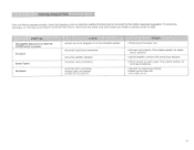
... the POWER switch is not completely inserted. • Firmly plug In the power cord. • Incorrect output cord connections. • Incorrect amplifier operation. • Incorrect cable connections. ll ,Ndq,,,i' l % ;Itrli! ,,'';', ,7,'L,1 II ,,IP('414:tqg '1,,14, .l',!,..ii,,"t,I 1 I ;, lid 0!I ."1-" - 'if.".. ea Incorrect cord connections. e Video unit not turned on . 14 If it cannot be defective. • Connect the video plugs correctly. • Select correct video unit. • Turn video unit on . • Connect cord properly. to Set the amplifier controls...
... the POWER switch is not completely inserted. • Firmly plug In the power cord. • Incorrect output cord connections. • Incorrect amplifier operation. • Incorrect cable connections. ll ,Ndq,,,i' l % ;Itrli! ,,'';', ,7,'L,1 II ,,IP('414:tqg '1,,14, .l',!,..ii,,"t,I 1 I ;, lid 0!I ."1-" - 'if.".. ea Incorrect cord connections. e Video unit not turned on . 14 If it cannot be defective. • Connect the video plugs correctly. • Select correct video unit. • Turn video unit on . • Connect cord properly. to Set the amplifier controls...
AVS-700 OWNERS MANUAL
Page 16
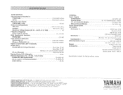
... LA VALLEE CEDEX 2. HAMAMATSU. and Australia model 100W me (Europe, U.K. SPECIFICATIONS, AUDIO SECTION Input Sensitivity/Impedance PHONO MM 2.5 mV/47 k-ohms CD etc. 150 mV/47 k-ohms Maximum Input Signal PHONO MM, 1kHz 110 mV Output Level/Impedance REC OUT 150 mV/1.6 k-ohms OUTPUT 150 mV/1 k-ohms Maxim um Voltage Output (20 Hz - 20 kH, 0.1% THD) 3V Frequency Response 20 Hz to change without notice. Video cord x Audio cord x Remote control transmitter x Battery (size "AAA", R03...
... LA VALLEE CEDEX 2. HAMAMATSU. and Australia model 100W me (Europe, U.K. SPECIFICATIONS, AUDIO SECTION Input Sensitivity/Impedance PHONO MM 2.5 mV/47 k-ohms CD etc. 150 mV/47 k-ohms Maximum Input Signal PHONO MM, 1kHz 110 mV Output Level/Impedance REC OUT 150 mV/1.6 k-ohms OUTPUT 150 mV/1 k-ohms Maxim um Voltage Output (20 Hz - 20 kH, 0.1% THD) 3V Frequency Response 20 Hz to change without notice. Video cord x Audio cord x Remote control transmitter x Battery (size "AAA", R03...


