

Owner's Manual
Page 5
... of hum such as that specified on the surface of the power amplifier/subwoofer unit assure proper ventilation of the unit. Condensation can cause the unit to vibration and excessive dust, heat, cold or moisture. YAMAHA shall not be liable for any damage resulting from use this unit...playback is possible (about 1 hour). • Remote control Wipe off condensation on the floor. s Choose the installation location of this manual carefully. YAMAHA will rise rapidly. WARNING TO REDUCE THE RISK OF FIRE OR ELECTRIC SHOCK, DO NOT EXPOSE THIS APPLIANCE TO RAIN OR MOISTURE. Serial No.: ...
... of hum such as that specified on the surface of the power amplifier/subwoofer unit assure proper ventilation of the unit. Condensation can cause the unit to vibration and excessive dust, heat, cold or moisture. YAMAHA shall not be liable for any damage resulting from use this unit...playback is possible (about 1 hour). • Remote control Wipe off condensation on the floor. s Choose the installation location of this manual carefully. YAMAHA will rise rapidly. WARNING TO REDUCE THE RISK OF FIRE OR ELECTRIC SHOCK, DO NOT EXPOSE THIS APPLIANCE TO RAIN OR MOISTURE. Serial No.: ...

Owner's Manual
Page 6
... terminal which is the value measured at a distance of about 200mm from the mains lead must be connected to the earth terminal of the power amplifier/subwoofer (SW-AV1) must be connected to the terminal which is hazardous if engaged in your plug. Recording of fire or electric shock, do not...
... terminal which is the value measured at a distance of about 200mm from the mains lead must be connected to the earth terminal of the power amplifier/subwoofer (SW-AV1) must be connected to the terminal which is hazardous if engaged in your plug. Recording of fire or electric shock, do not...

Owner's Manual
Page 8
... makes sound more real and more powerful. OUTLINE OF THIS SYSTEM SYSTEM CONFIGURATION This system is a multi-channel audio system which consists of Yamaha original digital sound fields simulating an actual concert hall, live house, etc. You will be given great enjoyment in CD player and tuner...SW-AV1 (6 channel power amplifier and Active Servo Processing Subwoofer system) NX-AV1 (Full range speakers used for front, center and rear speakers) TCD-AV1 (Main control unit including Tuner, CD player and Digital Sound Field Processor) PUSH OPEN POWER MINI COMPONENT SYSTEM AV-1 PRO LOGIC DSP OFF...
... makes sound more real and more powerful. OUTLINE OF THIS SYSTEM SYSTEM CONFIGURATION This system is a multi-channel audio system which consists of Yamaha original digital sound fields simulating an actual concert hall, live house, etc. You will be given great enjoyment in CD player and tuner...SW-AV1 (6 channel power amplifier and Active Servo Processing Subwoofer system) NX-AV1 (Full range speakers used for front, center and rear speakers) TCD-AV1 (Main control unit including Tuner, CD player and Digital Sound Field Processor) PUSH OPEN POWER MINI COMPONENT SYSTEM AV-1 PRO LOGIC DSP OFF...
Owner's Manual
Page 14
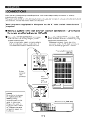
...CONNECTOR AUDIO OUTPUT ANTENNA FM 75Ω UNBAL. s Making a system connection between the main control unit (TCD-AV1) and the power amplifier/subwoofer (SW-AV1) 1 Connect the SYSTEM CONNECTOR terminals on both units with each other by using the provided connection cord. * Make ...plug to the "L" terminal. 1 System connector cable (provided) L R INPUT MARK SYSTEM CONNECTOR FROM TCD-AV1 2 Audio connection cord (provided) Power amplifier/subwoofer (SW-AV1) L R INPUT MARK SYSTEM CONNECTOR FROM TCD-AV1 RL FRONT RC L REAR CENTER REAR Caution Be careful not to both terminals, ...
...CONNECTOR AUDIO OUTPUT ANTENNA FM 75Ω UNBAL. s Making a system connection between the main control unit (TCD-AV1) and the power amplifier/subwoofer (SW-AV1) 1 Connect the SYSTEM CONNECTOR terminals on both units with each other by using the provided connection cord. * Make ...plug to the "L" terminal. 1 System connector cable (provided) L R INPUT MARK SYSTEM CONNECTOR FROM TCD-AV1 2 Audio connection cord (provided) Power amplifier/subwoofer (SW-AV1) L R INPUT MARK SYSTEM CONNECTOR FROM TCD-AV1 RL FRONT RC L REAR CENTER REAR Caution Be careful not to both terminals, ...

Owner's Manual
Page 15
English CONNECTIONS s Connecting the speakers (NX-AV1) to the power amplifier/subwoofer (SW-AV1) Right front speaker Left front speaker Right rear speaker Center speaker Left rear speaker RL FRONT RC L REAR CENTER REAR L R INPUT MARK SYSTEM CONNECTOR FROM TCD-AV1 RL FRONT RC L REAR CENTER REAR E-13 Power amplifier/subwoofer (SW-AV1)
English CONNECTIONS s Connecting the speakers (NX-AV1) to the power amplifier/subwoofer (SW-AV1) Right front speaker Left front speaker Right rear speaker Center speaker Left rear speaker RL FRONT RC L REAR CENTER REAR L R INPUT MARK SYSTEM CONNECTOR FROM TCD-AV1 RL FRONT RC L REAR CENTER REAR E-13 Power amplifier/subwoofer (SW-AV1)

Owner's Manual
Page 16
...-AV1. terminals on the rear of the speaker wires is correct, that is useful for preventing wrong connections between the SPEAKERS terminals on the power amplifier/subwoofer (SW-AV1) and the speaker terminals on both of the speakers (NX-AV1) are observed. On NX-AV1: Red: positive (+) Black: negative (-) Œ ... 5mm (1/4") insulation from the speaker wires.] Ž Release the tab and secure the wire. The speaker connected to the SPEAKERS terminals on both the power amplifier/subwoofer (SW-AV1) and speaker, and connect the wire with no sound will be heard from the speakers.
...-AV1. terminals on the rear of the speaker wires is correct, that is useful for preventing wrong connections between the SPEAKERS terminals on the power amplifier/subwoofer (SW-AV1) and the speaker terminals on both of the speakers (NX-AV1) are observed. On NX-AV1: Red: positive (+) Black: negative (-) Œ ... 5mm (1/4") insulation from the speaker wires.] Ž Release the tab and secure the wire. The speaker connected to the SPEAKERS terminals on both the power amplifier/subwoofer (SW-AV1) and speaker, and connect the wire with no sound will be heard from the speakers.
Owner's Manual
Page 19
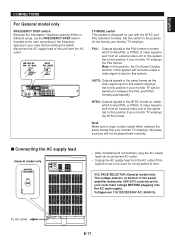
... matter which format (PAL or NTSC) of time. Set to this system. VOLTAGE SELECTOR (General model only) The voltage selector on bottom of the power amplifier/subwoofer (SW-AV1) must be used for a long period of video signal is input to this position if your monitor TV can be played back...
... matter which format (PAL or NTSC) of time. Set to this system. VOLTAGE SELECTOR (General model only) The voltage selector on bottom of the power amplifier/subwoofer (SW-AV1) must be used for a long period of video signal is input to this position if your monitor TV can be played back...

Owner's Manual
Page 55
s Amplifier section Minimum RMS Output Power per Channel Front L, R 6 ohms, 1 kHz, 10% THD 30W+30W Center 6 ohms, 1 kHz, 10% THD 30W Rear L, R 6 ohms, 1 kHz, 10% THD ... General models 530 - 1,710 kHz [U.K., Europe, Australia and Singapore models 531 - 1,611 kHz LW [U.K. The performance specification figures indicated are nominal values of continuous improvement, YAMAHA reserves the right to 10 MHz, -3 dB s Tuner section Tuning Range FM [U.S.A. and Europe models only].......... 560 µV/m s CD player section Type Single CD Player...
s Amplifier section Minimum RMS Output Power per Channel Front L, R 6 ohms, 1 kHz, 10% THD 30W+30W Center 6 ohms, 1 kHz, 10% THD 30W Rear L, R 6 ohms, 1 kHz, 10% THD ... General models 530 - 1,710 kHz [U.K., Europe, Australia and Singapore models 531 - 1,611 kHz LW [U.K. The performance specification figures indicated are nominal values of continuous improvement, YAMAHA reserves the right to 10 MHz, -3 dB s Tuner section Tuning Range FM [U.S.A. and Europe models only].......... 560 µV/m s CD player section Type Single CD Player...

