

MG32/14FX MG24/14FX Owners Manual
Page 1
MIXING CONSOLE Owner's Manual MG32/14 FX MG24/14 FX E
MIXING CONSOLE Owner's Manual MG32/14 FX MG24/14 FX E
MG32/14FX MG24/14FX Owners Manual
Page 3
PRECAUTIONS PLEASE READ CAREFULLY BEFORE PROCEEDING * Please keep this manual in a safe place for a long period of time at..., remove all devices. These precautions include, but are located on the buttons, switches or connectors. 3 MG32/14FX, MG24/14FX If some trouble or malfunction occurs, immediately turn off for the device. Upside down or on or off... volume levels to unplug the power cord from the outlet, and have the device inspected by qualified Yamaha service personnel. Depending on the device (vents, etc.). • Avoid inserting or dropping foreign objects (paper,...
PRECAUTIONS PLEASE READ CAREFULLY BEFORE PROCEEDING * Please keep this manual in a safe place for a long period of time at..., remove all devices. These precautions include, but are located on the buttons, switches or connectors. 3 MG32/14FX, MG24/14FX If some trouble or malfunction occurs, immediately turn off for the device. Upside down or on or off... volume levels to unplug the power cord from the outlet, and have the device inspected by qualified Yamaha service personnel. Depending on the device (vents, etc.). • Avoid inserting or dropping foreign objects (paper,...
MG32/14FX MG24/14FX Owners Manual
Page 4
... This product has been tested and found to comply with the requirements listed in to products distributed by Yamaha-Kemble Music (U.K.) Ltd. (3 wires). 4 MG32/14FX, MG24/14FX Utilize power outlets that interference will not result in use this product in this product is being affected by...cations to the device, or data that is found in all installation instructions. Compliance with other electronic devices. If this Owner's Manual are trademarks or registered trademarks of components with the letter L or coloured RED. • This applies only to co-axial ...
... This product has been tested and found to comply with the requirements listed in to products distributed by Yamaha-Kemble Music (U.K.) Ltd. (3 wires). 4 MG32/14FX, MG24/14FX Utilize power outlets that interference will not result in use this product in this product is being affected by...cations to the device, or data that is found in all installation instructions. Compliance with other electronic devices. If this Owner's Manual are trademarks or registered trademarks of components with the letter L or coloured RED. • This applies only to co-axial ...
MG32/14FX MG24/14FX Owners Manual
Page 6
...free operation for a total of 14 outputs. Contents Introduction 6 Features 6 Connecting to selectively monitor the input and output signals through this manual in an SR setup or as an auxiliary stereo input. The phantom power can use the AUX and GROUP outputs both microphones and ... and for the 2TR IN bus, together with independent AFL switches for each AUX and GROUP output and for your purchase of the YAMAHA MG32/14FX or MG24/14FX mixing console. Also provides four line-level stereo inputs. ● Built-in eight-channel blocks. ● Dual RETURN jacks can apply...
...free operation for a total of 14 outputs. Contents Introduction 6 Features 6 Connecting to selectively monitor the input and output signals through this manual in an SR setup or as an auxiliary stereo input. The phantom power can use the AUX and GROUP outputs both microphones and ... and for the 2TR IN bus, together with independent AFL switches for each AUX and GROUP output and for your purchase of the YAMAHA MG32/14FX or MG24/14FX mixing console. Also provides four line-level stereo inputs. ● Built-in eight-channel blocks. ● Dual RETURN jacks can apply...
MG32/14FX MG24/14FX Owners Manual
Page 8
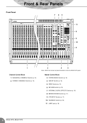
Front Panel Front & Rear Panels 7 65 11 8 9 10 8 1 Channel Control Block 1 MONAURAL CHANNELS Section (p. 10) 2 STEREO CHANNELS Section (p. 10) 2 4 3 Note: Within this manual, all panel illustrations show the MG32/14FX panel. Master Control Block 3 STEREO/MONO Section (p. 13) 4 GROUP Section (p. 14) 5 SEND Section (p. 14) 6 RETURN Section (p. 15) 7 INTERNAL DIGITAL EFFECTS Section (p. 16) 8 METER/PHONES Section (p. 17) 9 2TR INPUT Section (p. 17) 10 TALKBACK Section (p. 18) 11 LAMP Jack (p. 18) 8 MG32/14FX, MG24/14FX
Front Panel Front & Rear Panels 7 65 11 8 9 10 8 1 Channel Control Block 1 MONAURAL CHANNELS Section (p. 10) 2 STEREO CHANNELS Section (p. 10) 2 4 3 Note: Within this manual, all panel illustrations show the MG32/14FX panel. Master Control Block 3 STEREO/MONO Section (p. 13) 4 GROUP Section (p. 14) 5 SEND Section (p. 14) 6 RETURN Section (p. 15) 7 INTERNAL DIGITAL EFFECTS Section (p. 16) 8 METER/PHONES Section (p. 17) 9 2TR INPUT Section (p. 17) 10 TALKBACK Section (p. 18) 11 LAMP Jack (p. 18) 8 MG32/14FX, MG24/14FX

MG32/14FX MG24/14FX Owners Manual
Page 9
Rear Panel Front & Rear Panels 13 Rear Input/Output Block 12 CHANNEL I/O Section (p. 19) 13 MASTER I/O Section (p. 20) 12 Note: Within this manual, all panel illustrations show the MG32/14FX panel. 9 MG32/14FX, MG24/14FX
Rear Panel Front & Rear Panels 13 Rear Input/Output Block 12 CHANNEL I/O Section (p. 19) 13 MASTER I/O Section (p. 20) 12 Note: Within this manual, all panel illustrations show the MG32/14FX panel. 9 MG32/14FX, MG24/14FX
MG32/14FX MG24/14FX Owners Manual
Page 22
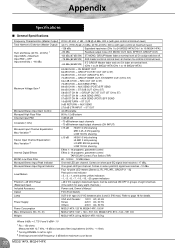
Appendix Specifications ■ General Specifications Frequency Characteristics (Master Output) Total Harmonic Distortion (Master Output) Hum and Noise (20 Hz - 20 kHz) 1 Input GAIN = Maximum Input PAD = OFF Input sensitivity = -60 dBu Maximum Voltage Gain 2 Monaural/Stereo Input Gain Control Monaural High Pass Filter Channel Input PAD Crosstalk (1 kHz) Monaural Input Channel Equalization: Max. Dimensions (W × H × D) Weight 20 Hz-20 kHz +1 dB, -3 dB @+4 dBu, 600 Ω (with gain control at minimum level) Variation 3 Internal Digital Effects MONO Low Pass Filter ...
Appendix Specifications ■ General Specifications Frequency Characteristics (Master Output) Total Harmonic Distortion (Master Output) Hum and Noise (20 Hz - 20 kHz) 1 Input GAIN = Maximum Input PAD = OFF Input sensitivity = -60 dBu Maximum Voltage Gain 2 Monaural/Stereo Input Gain Control Monaural High Pass Filter Channel Input PAD Crosstalk (1 kHz) Monaural Input Channel Equalization: Max. Dimensions (W × H × D) Weight 20 Hz-20 kHz +1 dB, -3 dB @+4 dBu, 600 Ω (with gain control at minimum level) Variation 3 Internal Digital Effects MONO Low Pass Filter ...
MG32/14FX MG24/14FX Owners Manual
Page 23
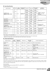
... RCA pin jack 2 ST INSERT IN [L, R] GROUP INSERT IN (1 - 4) CH INSERT IN (MG32/14FX: CHs 1 to 24) (MG24/14FX: CHs 1 to Environments: E1, E2, E3 and E4 23 MG32/14FX, MG24/14FX R: cold; Yamaha Corp. Since specifications, equipment or options may not be the same in ; S: ground]) REC...SEND (1-6) 150 Ω 600 Ω line +4 dBu (1.23 V) Phone jack (TRS) +20 dBu (7.75 V) (impedance balanced [T: hot; R: in this owner's manual are for information purposes only. S: ground]) PHONES 100 Ω 40 Ω phone 3 mW 75 mW Stereo phone jack Where 0 dBu = 0.775 V and 0 ...
... RCA pin jack 2 ST INSERT IN [L, R] GROUP INSERT IN (1 - 4) CH INSERT IN (MG32/14FX: CHs 1 to 24) (MG24/14FX: CHs 1 to Environments: E1, E2, E3 and E4 23 MG32/14FX, MG24/14FX R: cold; Yamaha Corp. Since specifications, equipment or options may not be the same in ; S: ground]) REC...SEND (1-6) 150 Ω 600 Ω line +4 dBu (1.23 V) Phone jack (TRS) +20 dBu (7.75 V) (impedance balanced [T: hot; R: in this owner's manual are for information purposes only. S: ground]) PHONES 100 Ω 40 Ω phone 3 mW 75 mW Stereo phone jack Where 0 dBu = 0.775 V and 0 ...

