

MG32/14FX MG24/14FX Owners Manual
Page 2
... your outlet, consult an electrician for replacement of the obsolete outlet. 10 Protect the power cord from the apparatus. 11 Only use this apparatus near any heat sources such as powersupply cord or plug is intended to alert the user to qualified service personnel. A polarized plug has two blades with the manufacturer's instructions. 8 Do not install near water. 6 Clean only with...
... your outlet, consult an electrician for replacement of the obsolete outlet. 10 Protect the power cord from the apparatus. 11 Only use this apparatus near any heat sources such as powersupply cord or plug is intended to alert the user to qualified service personnel. A polarized plug has two blades with the manufacturer's instructions. 8 Do not install near water. 6 Clean only with...
MG32/14FX MG24/14FX Owners Manual
Page 3
... listed below to avoid the possibility of physical injury to be malfunctioning, discontinue use . Handling caution • Avoid setting all connected cables. • When setting up the product, make sure to avoid the possibility of sound during use immediately and have the device inspected by qualified Yamaha service personnel. • If this happens, turn off the power switch, disconnect the electric plug...
... listed below to avoid the possibility of physical injury to be malfunctioning, discontinue use . Handling caution • Avoid setting all connected cables. • When setting up the product, make sure to avoid the possibility of sound during use immediately and have the device inspected by qualified Yamaha service personnel. • If this happens, turn off the power switch, disconnect the electric plug...
MG32/14FX MG24/14FX Owners Manual
Page 4
... be used. Cable/s supplied with moving contacts, such as switches, volume controls, and connectors, deteriorates over time. Utilize power outlets that are coloured in accordance with the following measures: Relocate either this product or the device that your plug proceed as indicated in the instructions contained in this manual, meets FCC requirements. If you can be connected to the terminal in the users manual...
... be used. Cable/s supplied with moving contacts, such as switches, volume controls, and connectors, deteriorates over time. Utilize power outlets that are coloured in accordance with the following measures: Relocate either this product or the device that your plug proceed as indicated in the instructions contained in this manual, meets FCC requirements. If you can be connected to the terminal in the users manual...
MG32/14FX MG24/14FX Owners Manual
Page 6
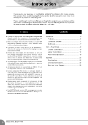
... part of 14 outputs. These jacks can apply a variety of internal effects to create custom mixes for targeted speakers or amps for connection to come. Features ● Provides 24 (MG32/14FX) or 16 (MG24/14FX) monaural input channels suitable for stage monitoring. ● An independently controlled MONO output jack feeds out a mix of the YAMAHA MG32/14FX or MG24/14FX mixing console. The phantom power can provide DC +48 power to any combination of the AUX buses. This console...
... part of 14 outputs. These jacks can apply a variety of internal effects to create custom mixes for targeted speakers or amps for connection to come. Features ● Provides 24 (MG32/14FX) or 16 (MG24/14FX) monaural input channels suitable for stage monitoring. ● An independently controlled MONO output jack feeds out a mix of the YAMAHA MG32/14FX or MG24/14FX mixing console. The phantom power can provide DC +48 power to any combination of the AUX buses. This console...
MG32/14FX MG24/14FX Owners Manual
Page 7
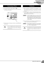
... connec- tor on the mixer. Setting Up (1) Before connecting to the appropriate input jack on the rear of the mixer. (3) Plug the other end to microphones and instruments, be sure that all of the mixer's channel faders and master control faders are set all the way down , turn off . Also be sure that all devices are turned off the power in the opposite order: Power amps (powered speakers) → mixer → peripheral devices. All...
... connec- tor on the mixer. Setting Up (1) Before connecting to the appropriate input jack on the rear of the mixer. (3) Plug the other end to microphones and instruments, be sure that all of the mixer's channel faders and master control faders are set all the way down , turn off . Also be sure that all devices are turned off the power in the opposite order: Power amps (powered speakers) → mixer → peripheral devices. All...
MG32/14FX MG24/14FX Owners Manual
Page 10
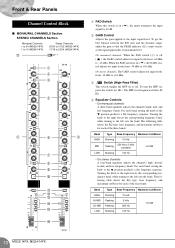
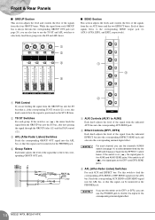
... cuts the band. Front & Rear Panels Channel Control Block ■ MONAURAL CHANNELS Section STEREO CHANNELS Section Monaural Channels 1 to 24 (MG32/14FX) 1 to 16 (MG24/14FX) Stereo Channels 25/26 to 31/32 (MG32/14FX) 17/18 to 23/24 (MG24/14FX) G 1 2 3 4 5 6 5 7 8 9 0 A B C D E F 1 PAD Switch When this switch is on just as the signal approaches its maximum level. To turn the HPF on ( ), the GAIN control adjusts for each band, setting the knob to 5 kHz...
... cuts the band. Front & Rear Panels Channel Control Block ■ MONAURAL CHANNELS Section STEREO CHANNELS Section Monaural Channels 1 to 24 (MG32/14FX) 1 to 16 (MG24/14FX) Stereo Channels 25/26 to 31/32 (MG32/14FX) 17/18 to 23/24 (MG24/14FX) G 1 2 3 4 5 6 5 7 8 9 0 A B C D E F 1 PAD Switch When this switch is on just as the signal approaches its maximum level. To turn the HPF on ( ), the GAIN control adjusts for each band, setting the knob to 5 kHz...
MG32/14FX MG24/14FX Owners Manual
Page 11
... control adjusts the signal's pan positioning into the Group 1-2 bus pair, into the Group 3-4 bus pair, and into the EFFECT bus. E ST Switch Set this switch to feed the channel's pre-channel-fader signal into the L input (odd channel) feed to the Group 1 and Group 3 buses and to the L line of the Stereo bus. A PFL (Pre-Fader Listen) Switch Use this switch on , press the switch in ( ) so that it lights up when a signal is no PRE switch for AUX5 and AUX6. To turn the channel...
... control adjusts the signal's pan positioning into the Group 1-2 bus pair, into the Group 3-4 bus pair, and into the EFFECT bus. E ST Switch Set this switch to feed the channel's pre-channel-fader signal into the L input (odd channel) feed to the Group 1 and Group 3 buses and to the L line of the Stereo bus. A PFL (Pre-Fader Listen) Switch Use this switch on , press the switch in ( ) so that it lights up when a signal is no PRE switch for AUX5 and AUX6. To turn the channel...
MG32/14FX MG24/14FX Owners Manual
Page 12
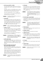
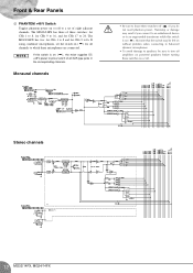
... 9 to16. If using condenser microphones, set of all channels to which these switches on or off to a set the switch on ( ), the mixer supplies DC +48 V power to 24. But note that the switch may result if you do not need phantom power. Front & Rear Panels G PHANTOM +48 V Switch Toggles phantom power on or off. Stereo channels 12 MG32/14FX, MG24/14FX Humming or damage may be left on without problem when connecting to balanced...
... 9 to16. If using condenser microphones, set of all channels to which these switches on or off to a set the switch on ( ), the mixer supplies DC +48 V power to 24. But note that the switch may result if you do not need phantom power. Front & Rear Panels G PHANTOM +48 V Switch Toggles phantom power on or off. Stereo channels 12 MG32/14FX, MG24/14FX Humming or damage may be left on without problem when connecting to balanced...
MG32/14FX MG24/14FX Owners Manual
Page 13
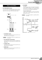
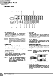
... adjust the main stereo output, the sub stereo output, and the mixed monaural output. 1 5 LPF (MONO) • LPF Switch Set this switch ON to apply a low-pass filter to the signal output from the ST bus. Front & Rear Panels Master Control Block ■ STEREO/MONO Section You use this section to independently adjust the levels of the outputs from the MONO output jack, or OFF to turn the dial. 5 2 4 3 1 ST SUB OUT Control Adjusts the level of the signal that feeds from the ST bus into the MONO output jack...
... adjust the main stereo output, the sub stereo output, and the mixed monaural output. 1 5 LPF (MONO) • LPF Switch Set this switch ON to apply a low-pass filter to the signal output from the ST bus. Front & Rear Panels Master Control Block ■ STEREO/MONO Section You use this section to independently adjust the levels of the outputs from the MONO output jack, or OFF to turn the dial. 5 2 4 3 1 ST SUB OUT Control Adjusts the level of the signal that feeds from the ST bus into the MONO output jack...
MG32/14FX MG24/14FX Owners Manual
Page 14
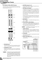
... & Rear Panels ■ GROUP Section This section adjusts the level and controls the flow of the signal from the indicated EFFECT bus into the corresponding EFFECT SEND jack and also into the corresponding internal digital effect. NOTE For each channel, you are also free to use the TO ST and AFL switches to AUX6) Each knob adjusts the level of the signal from the indicated AUX bus into the EFFECT 1 and 2 buses. If the switch...
... & Rear Panels ■ GROUP Section This section adjusts the level and controls the flow of the signal from the indicated EFFECT bus into the corresponding EFFECT SEND jack and also into the corresponding internal digital effect. NOTE For each channel, you are also free to use the TO ST and AFL switches to AUX6) Each knob adjusts the level of the signal from the indicated AUX bus into the EFFECT 1 and 2 buses. If the switch...

MG32/14FX MG24/14FX Owners Manual
Page 15
... (Pre-Fader Listen) Switch Use this switch to feed the corresponding RETURN signal, taken from before the ST and AUX Mix controls, into the PFL bus, so that you are inputting a stereo signal, the L and R signals are inputting a stereo signal, the L signal goes into the ST L line and the R signal goes into ST R line. To turn the PFL feed on, press the switch in ( ). 15 MG32/14FX, MG24/14FX Front & Rear Panels ■ RETURN Section This section adjusts...
... (Pre-Fader Listen) Switch Use this switch to feed the corresponding RETURN signal, taken from before the ST and AUX Mix controls, into the PFL bus, so that you are inputting a stereo signal, the L and R signals are inputting a stereo signal, the L signal goes into the ST L line and the R signal goes into ST R line. To turn the PFL feed on, press the switch in ( ). 15 MG32/14FX, MG24/14FX Front & Rear Panels ■ RETURN Section This section adjusts...
MG32/14FX MG24/14FX Owners Manual
Page 16
... (Pre-Fader Listen) Switches Use this switch to feed the corresponding digital effect signal, taken from the PHONES jack. The setting applies to Groups 1 and 2; Front & Rear Panels ■ INTERNAL DIGITAL EFFECTS Section You use this section to control the dual internal effects processor: to select the two effect types, to set the effects on or off, and to adjust the related signal levels and flows. 1 2 3 4 5 6 7 8 3 AUX PRE Controls (1 to 4) Each knob adjusts the level of the effected sound into the corresponding AUX bus...
... (Pre-Fader Listen) Switches Use this switch to feed the corresponding digital effect signal, taken from the PHONES jack. The setting applies to Groups 1 and 2; Front & Rear Panels ■ INTERNAL DIGITAL EFFECTS Section You use this section to control the dual internal effects processor: to select the two effect types, to set the effects on or off, and to adjust the related signal levels and flows. 1 2 3 4 5 6 7 8 3 AUX PRE Controls (1 to 4) Each knob adjusts the level of the effected sound into the corresponding AUX bus...

MG32/14FX MG24/14FX Owners Manual
Page 17
... ST bus. 2 PFL (Pre-Fader Listen) Switch Use this switch to feed the signal from the 2TR IN jack, taken from before the 2TR IN control, into the PFL bus, so that is input from the PHONES jack. If the GROUP switch is off , the left and right meters show the levels to the GROUP OUT jacks. The PEAK indicator lights up when the mixer's power is on. 2 STEREO Level Meters If the GROUP switch (4) is...
... ST bus. 2 PFL (Pre-Fader Listen) Switch Use this switch to feed the signal from the 2TR IN jack, taken from before the 2TR IN control, into the PFL bus, so that is input from the PHONES jack. If the GROUP switch is off , the left and right meters show the levels to the GROUP OUT jacks. The PEAK indicator lights up when the mixer's power is on. 2 STEREO Level Meters If the GROUP switch (4) is...
MG32/14FX MG24/14FX Owners Manual
Page 18
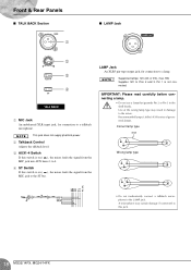
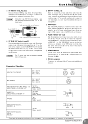
... supply phantom power. 2 Talkback Control Adjusts the talkback level. 3 AUX1-4 Switch If this switch is not connected. Pin 1 is on ( ), the mixer feeds the signal from the MIC jack into AUX buses 1 to 4. 4 ST Switch If this switch is on ( ), the mixer feeds the signal from the MIC jack to this jack. 18 MG32/14FX, MG24/14FX NOTE Supported lamps: 12V (AC or DC), max. 5W. A microphone may result in damage to the LAMP jack. Front & Rear Panels...
... supply phantom power. 2 Talkback Control Adjusts the talkback level. 3 AUX1-4 Switch If this switch is not connected. Pin 1 is on ( ), the mixer feeds the signal from the MIC jack into AUX buses 1 to 4. 4 ST Switch If this switch is on ( ), the mixer feeds the signal from the MIC jack to this jack. 18 MG32/14FX, MG24/14FX NOTE Supported lamps: 12V (AC or DC), max. 5W. A microphone may result in damage to the LAMP jack. Front & Rear Panels...
MG32/14FX MG24/14FX Owners Manual
Page 19
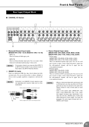
... connect to 16) • INPUT A These are balanced XLR input jacks. • INPUT B These are unbalanced TRS (tip, ring, sleeve) phone-type bidirectional jacks. Please connect to an INSERT I/O jack requires a special separately-sold insertion cable such as graphic equalizers, compressors, and noise filters. To the input jack of the external processor To the INSERT I/O jack Sleeve Tip Sleeve Ring Tip To the output jack of the external processor 3 Stereo-Channel Input Jacks (MG32/14FX...
... connect to 16) • INPUT A These are balanced XLR input jacks. • INPUT B These are unbalanced TRS (tip, ring, sleeve) phone-type bidirectional jacks. Please connect to an INSERT I/O jack requires a special separately-sold insertion cable such as graphic equalizers, compressors, and noise filters. To the input jack of the external processor To the INSERT I/O jack Sleeve Tip Sleeve Ring Tip To the output jack of the external processor 3 Stereo-Channel Input Jacks (MG32/14FX...
MG32/14FX MG24/14FX Owners Manual
Page 20
... use these jacks is not adjusted by the ST master fader and is being output from an external effector (reverb, delay, etc.). NOTE Connection to an INSERT I/O jack requires a special separately-sold insertion cable such as a CD player or DAT deck) directly to 4) These are impedance-balanced phone output jacks. Front & Rear Panels ■ MASTER I/O Section B A 87 1 C 0 9 6 5 4 32 1 RETURN Jacks (1, 2) These are impedance-balanced phone jacks. To the input jack of the external processor To the INSERT I/O jack...
... use these jacks is not adjusted by the ST master fader and is being output from an external effector (reverb, delay, etc.). NOTE Connection to an INSERT I/O jack requires a special separately-sold insertion cable such as a CD player or DAT deck) directly to 4) These are impedance-balanced phone output jacks. Front & Rear Panels ■ MASTER I/O Section B A 87 1 C 0 9 6 5 4 32 1 RETURN Jacks (1, 2) These are impedance-balanced phone jacks. To the input jack of the external processor To the INSERT I/O jack...
MG32/14FX MG24/14FX Owners Manual
Page 21
... accept connection to set the delay. You use with the mixer. The level for this output is a mix of the ST bus's L and R signals. The level for this output is controlled by the MONO fader in the Master Control block (see page 13). The mixer will be unbalanced. You would typically use monaural plugs, the connection will automatically set the delay to set the power off ( ). B POWER Switch Use this jack and then set internal EFFECT 2 to [16] TAP DELAY, you use these jacks, for this output is adjusted...
... accept connection to set the delay. You use with the mixer. The level for this output is a mix of the ST bus's L and R signals. The level for this output is controlled by the MONO fader in the Master Control block (see page 13). The mixer will be unbalanced. You would typically use monaural plugs, the connection will automatically set the delay to set the power off ( ). B POWER Switch Use this jack and then set internal EFFECT 2 to [16] TAP DELAY, you use these jacks, for this output is adjusted...
MG32/14FX MG24/14FX Owners Manual
Page 22
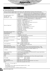
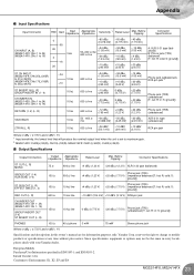
... Frequency Characteristics (Master Output) Total Harmonic Distortion (Master Output) Hum and Noise (20 Hz - 20 kHz) 1 Input GAIN = Maximum Input PAD = OFF Input sensitivity = -60 dBu Maximum Voltage Gain 2 Monaural/Stereo Input Gain Control Monaural High Pass Filter Channel Input PAD Crosstalk (1 kHz) Monaural Input Channel Equalization: Max. Variation 3 Internal Digital Effects MONO Low Pass Filter Monaural/Stereo Input Peak Indicator Monaural/Stereo Input Signal Indicator Level Meters Phantom +48 VDC Power (Balanced input) Included Accessory Option Lamp Power Supply Power Consumption Max...
... Frequency Characteristics (Master Output) Total Harmonic Distortion (Master Output) Hum and Noise (20 Hz - 20 kHz) 1 Input GAIN = Maximum Input PAD = OFF Input sensitivity = -60 dBu Maximum Voltage Gain 2 Monaural/Stereo Input Gain Control Monaural High Pass Filter Channel Input PAD Crosstalk (1 kHz) Monaural Input Channel Equalization: Max. Variation 3 Internal Digital Effects MONO Low Pass Filter Monaural/Stereo Input Peak Indicator Monaural/Stereo Input Signal Indicator Level Meters Phantom +48 VDC Power (Balanced input) Included Accessory Option Lamp Power Supply Power Consumption Max...
MG32/14FX MG24/14FX Owners Manual
Page 23
... EN55103-1 and EN55103-2. Yamaha Corp. European Models Purchaser/User Information specified in ; R: in this owner's manual are for information purposes only. S: ground]) ST SUB OUT (L, R) EFFECT SNED (1, 2) 150 Ω 10 kΩ line +4 dBu (1.23 V) Phone jack (TRS) +20 dBu (7.75 V) (impedance balanced [T: hot; S: ground]) PHONES 100 Ω 40 Ω phone 3 mW 75 mW Stereo phone jack Where 0 dBu = 0.775...
... EN55103-1 and EN55103-2. Yamaha Corp. European Models Purchaser/User Information specified in ; R: in this owner's manual are for information purposes only. S: ground]) ST SUB OUT (L, R) EFFECT SNED (1, 2) 150 Ω 10 kΩ line +4 dBu (1.23 V) Phone jack (TRS) +20 dBu (7.75 V) (impedance balanced [T: hot; S: ground]) PHONES 100 Ω 40 Ω phone 3 mW 75 mW Stereo phone jack Where 0 dBu = 0.775...

MG32/14FX MG24/14FX Owners Manual
Page 24
... gain Delay time 0-100 0-99% 100 ms (600 bpm) -2690 ms (22.3 bpm)* * The LED can be adjusted by the PARAMETER control. Reverb time 0.3-10.0 s Ideal echo for vocals. It lets you actually press the switch. Adds a sense of a small room. The well-known effect used to EFFECT 1 and 2 No. Appendix ■ Digital effect type list • Common to distort the sound. Produces a hard-sounding rever- An effect that changes the pitch...
... gain Delay time 0-100 0-99% 100 ms (600 bpm) -2690 ms (22.3 bpm)* * The LED can be adjusted by the PARAMETER control. Reverb time 0.3-10.0 s Ideal echo for vocals. It lets you actually press the switch. Adds a sense of a small room. The well-known effect used to EFFECT 1 and 2 No. Appendix ■ Digital effect type list • Common to distort the sound. Produces a hard-sounding rever- An effect that changes the pitch...


