

Owner's Manual
Page 6
... EQ Program List 67 Storing EQ Programs 68 Recalling EQ Programs 69 Editing EQ Program Titles 70 Preset EQ Program Parameters 71 7 Solo, Monitors & Meters 75 About Monitor & Solo 76 Monitor Outputs 77 Phones 77 Two-track Input (2TR IN 77 Monitor Setup 78 Using Monitor 78 Monitor Block Diagram 79 Solo Setup 80 Using Solo 81 Solo Block Diagram 82 Metering Signal Levels 83 Main Stereo Meters 84 Peak Hold 84 Setting the Metering Point 85 Option I/O Meters (input channels 17-24 85 Effects Send Meters 86 8 Stereo Output 87...
... EQ Program List 67 Storing EQ Programs 68 Recalling EQ Programs 69 Editing EQ Program Titles 70 Preset EQ Program Parameters 71 7 Solo, Monitors & Meters 75 About Monitor & Solo 76 Monitor Outputs 77 Phones 77 Two-track Input (2TR IN 77 Monitor Setup 78 Using Monitor 78 Monitor Block Diagram 79 Solo Setup 80 Using Solo 81 Solo Block Diagram 82 Metering Signal Levels 83 Main Stereo Meters 84 Peak Hold 84 Setting the Metering Point 85 Option I/O Meters (input channels 17-24 85 Effects Send Meters 86 8 Stereo Output 87...
Owner's Manual
Page 12
... the Scene Memories Chapter deals with the organization of 01V-related jargon is provided on page 293. 2 Chapter 1-Welcome to the 01V Welcome to the 01V Thank you 'll need in their own chapters. Based on the highly successful Yamaha digital mixer series, the Yamaha 01V has been designed with the important information at the buses. 01V Installation Site the 01V on input channels, aux sends, and the stereo output...
... the Scene Memories Chapter deals with the organization of 01V-related jargon is provided on page 293. 2 Chapter 1-Welcome to the 01V Welcome to the 01V Thank you 'll need in their own chapters. Based on the highly successful Yamaha digital mixer series, the Yamaha 01V has been designed with the important information at the buses. 01V Installation Site the 01V on input channels, aux sends, and the stereo output...
Owner's Manual
Page 13
...Omni outs (AUX, BUS, CH DIRECT, STEREO) • Option I/O slot for digital interface with 8-track digital multitrack recorders • 8 assignable digital outputs from an Option I/O card (Tascam, ADAT, AES/EBU) • Coaxial-type digital input and output • Versatile solo modes for comprehensive monitoring • 3 fader groups for multiple fader control • 3 mute groups for multiple mute control • 250 ms input delay (1-16) and 300 ms output delay (STEREO OUT, OMNI OUTs) • Channel Copy function • Stereo-pair operation for input channels, aux sends, and bus outs...
...Omni outs (AUX, BUS, CH DIRECT, STEREO) • Option I/O slot for digital interface with 8-track digital multitrack recorders • 8 assignable digital outputs from an Option I/O card (Tascam, ADAT, AES/EBU) • Coaxial-type digital input and output • Versatile solo modes for comprehensive monitoring • 3 fader groups for multiple fader control • 3 mute groups for multiple mute control • 250 ms input delay (1-16) and 300 ms output delay (STEREO OUT, OMNI OUTs) • Channel Copy function • Stereo-pair operation for input channels, aux sends, and bus outs...
Owner's Manual
Page 14
...-track digital recorder using third-generation Yamaha DSPs, as used for both recording and mixing. Analog mixers do this without introducing any new distortions and noise. The stereo output signal is a four-bus mixer, assigning the four buses and four aux sends, or the channel direct outs to the Option I /O digital outputs. Input channels 13 through 24 feature an attenuator, two-band parametric EQ, and can be connected directly to a modular digital multitrack recorder, thereby keeping audio data in the digital...
...-track digital recorder using third-generation Yamaha DSPs, as used for both recording and mixing. Analog mixers do this without introducing any new distortions and noise. The stereo output signal is a four-bus mixer, assigning the four buses and four aux sends, or the channel direct outs to the Option I /O digital outputs. Input channels 13 through 24 feature an attenuator, two-band parametric EQ, and can be connected directly to a modular digital multitrack recorder, thereby keeping audio data in the digital...
Owner's Manual
Page 15
... information. See "Assigning Faders & On Buttons" on page 194 and "User Defined MIDI Controllers" on page 32 for more information. The STEREO OUT features 20-bit 8-times oversampling D/A converters, while the MONITOR OUT and OMNI OUTs feature 18-bit 8-times oversampling D/A converters. High and low EQ bands can be used as the stereo output fader or aux or effects send master level faders. Faders on the selected Fader mode. Input channels 17 through 16...
... information. See "Assigning Faders & On Buttons" on page 194 and "User Defined MIDI Controllers" on page 32 for more information. The STEREO OUT features 20-bit 8-times oversampling D/A converters, while the MONITOR OUT and OMNI OUTs feature 18-bit 8-times oversampling D/A converters. High and low EQ bands can be used as the stereo output fader or aux or effects send master level faders. Faders on the selected Fader mode. Input channels 17 through 16...

Owner's Manual
Page 16
... eight digital inputs (input channels 17 through the effects return channels. See "About Option I /O card offering four analog outputs is used by the Yamaha 02R and 03D Digital Recording Consoles, such as the trigger signal), or triggered by the Effect 1 and Effect 2 buses, and the processed signals are available on page 213 for quick EQ and pan adjustments. The Coaxial DIGITAL STEREO IN and OUT allow you to represent rotary controls, switches, and faders...
... eight digital inputs (input channels 17 through the effects return channels. See "About Option I /O card offering four analog outputs is used by the Yamaha 02R and 03D Digital Recording Consoles, such as the trigger signal), or triggered by the Effect 1 and Effect 2 buses, and the processed signals are available on page 213 for quick EQ and pan adjustments. The Coaxial DIGITAL STEREO IN and OUT allow you to represent rotary controls, switches, and faders...

Owner's Manual
Page 58
... parameters are linked when channels are not linked. 52 Chapter 5-Input Channels Pairing Input Channels Input channels 1 through 12 can be paired together for more information. The following dialog box appears. RESET BOTH-Reset both input channels simultaneously. Routing switches, [SOLO] buttons, phase, panpots, aux panpots, and fade time on/off are paired: attenuators, EQ, dynamics, delays, [ON], and [SEL] buttons, faders, aux sends, effects sends, and pre/post settings. Panpot operation depends on page 48 for stereo signal processing.
... parameters are linked when channels are not linked. 52 Chapter 5-Input Channels Pairing Input Channels Input channels 1 through 12 can be paired together for more information. The following dialog box appears. RESET BOTH-Reset both input channels simultaneously. Routing switches, [SOLO] buttons, phase, panpots, aux panpots, and fade time on/off are paired: attenuators, EQ, dynamics, delays, [ON], and [SEL] buttons, faders, aux sends, effects sends, and pre/post settings. Panpot operation depends on page 48 for stereo signal processing.

Owner's Manual
Page 86
..., Monitors & Meters Solo Setup The Solo function, available on input channels 1 through 24 and the effects returns, is used to +6 dB. 01V-Owner's Manual Use the [SETUP] button to DISABLE, signals are turned on SETUP page 2. When set to locate SETUP page 2 shown below. 2. Only channels that are turned off are not soloed, the [SOLO] indicator on the soloed channel lights up instead of the solo signal from the Stereo bus. This switch is used to set to the monitor...
..., Monitors & Meters Solo Setup The Solo function, available on input channels 1 through 24 and the effects returns, is used to +6 dB. 01V-Owner's Manual Use the [SETUP] button to DISABLE, signals are turned on SETUP page 2. When set to locate SETUP page 2 shown below. 2. Only channels that are turned off are not soloed, the [SOLO] indicator on the soloed channel lights up instead of the solo signal from the Stereo bus. This switch is used to set to the monitor...

Owner's Manual
Page 87
... are using headphones, set to MONITOR. 3. For Input Channels 17-24 6. Set the MONITOR OUT LEVEL control midway. When a channel is set to AFL, you won't hear anything. 01V-Owner's Manual If SOLO SETUP LISTEN is soloed, its [SOLO] button and the main SOLO indicator flash. For Effects Returns 1 & 2 8. Otherwise, you must raise the soloed channel's fader. Connect a monitoring system (amp, speakers) to solo channels. Make sure that the MONITOR-2TR IN switch is set the PHONES LEVEL control midway. 4. Using...
... are using headphones, set to MONITOR. 3. For Input Channels 17-24 6. Set the MONITOR OUT LEVEL control midway. When a channel is set to AFL, you won't hear anything. 01V-Owner's Manual If SOLO SETUP LISTEN is soloed, its [SOLO] button and the main SOLO indicator flash. For Effects Returns 1 & 2 8. Otherwise, you must raise the soloed channel's fader. Connect a monitoring system (amp, speakers) to solo channels. Make sure that the MONITOR-2TR IN switch is set the PHONES LEVEL control midway. 4. Using...

Owner's Manual
Page 89
... for input and output meters can also be set on HOME page 5. Input channels 1-16 HOME page 1 displays signal level meters for input channels 1 through 16, the stereo output, aux sends, and effects sends can be metered using the main stereo meters or the meters on HOME page 4. The decibel value below each meter indicates the position of the stereo fader (ST) is also shown. See "Viewing Input Channel Settings" on page 57 for more information. 01V-Owner's Manual Effects Returns, Aux Sends & Bus Outs HOME page 2 displays signal level meters...
... for input and output meters can also be set on HOME page 5. Input channels 1-16 HOME page 1 displays signal level meters for input channels 1 through 16, the stereo output, aux sends, and effects sends can be metered using the main stereo meters or the meters on HOME page 4. The decibel value below each meter indicates the position of the stereo fader (ST) is also shown. See "Viewing Input Channel Settings" on page 57 for more information. 01V-Owner's Manual Effects Returns, Aux Sends & Bus Outs HOME page 2 displays signal level meters...

Owner's Manual
Page 107
... the [ENTER] button. RESET BOTH-Reset both aux sends operate independently. 01V-Owner's Manual Releasing Aux Send Pairs 1. On SETUP page 4, use the cursor buttons to select aux pair 1/2 or 3/4, and then press the [ENTER] button. The following dialog box appears. 2. The stereo pair is broken, and both aux sends to aux send 1. When paired, the EQ, dynamics, master faders, ON buttons, and monitors of aux send 1 to select a pairing mode, and then press the [ENTER] button. Use the cursor buttons to aux send 2.
... the [ENTER] button. RESET BOTH-Reset both aux sends operate independently. 01V-Owner's Manual Releasing Aux Send Pairs 1. On SETUP page 4, use the cursor buttons to select aux pair 1/2 or 3/4, and then press the [ENTER] button. The following dialog box appears. 2. The stereo pair is broken, and both aux sends to aux send 1. When paired, the EQ, dynamics, master faders, ON buttons, and monitors of aux send 1 to select a pairing mode, and then press the [ENTER] button. Use the cursor buttons to aux send 2.

Owner's Manual
Page 116
When paired, the master faders and ON buttons are now configured as shown below. 2. RESET BOTH-Reset both bus outs operate independently. 01V-Owner's Manual On SETUP page 4, use the cursor buttons to select bus pair 1/2 or 3/4, and then press the [ENTER] button. Use the cursor buttons to select the paired bus switch, and then press the [ENTER] button. BUS 2 -> 1-Copy the settings of bus out 1 to bus out 1. Releasing Bus Out Pairs 1. Making Bus Out Pairs...
When paired, the master faders and ON buttons are now configured as shown below. 2. RESET BOTH-Reset both bus outs operate independently. 01V-Owner's Manual On SETUP page 4, use the cursor buttons to select bus pair 1/2 or 3/4, and then press the [ENTER] button. Use the cursor buttons to select the paired bus switch, and then press the [ENTER] button. BUS 2 -> 1-Copy the settings of bus out 1 to bus out 1. Releasing Bus Out Pairs 1. Making Bus Out Pairs...

Owner's Manual
Page 124
... information. The meters indicate effects returns signal levels for the selected effects processor. 01V-Owner's Manual There are returned via effect returns 1 and 2. Effects processors are the effects parameters, the number of which contains 42 preset programs and 57 user programs. See "Effects Library" on the type of effect is using the up and down icon on this page, Effect 1 is using a HALL reverb, while Effect 2 is displayed above the effects returns level control icons. On...
... information. The meters indicate effects returns signal levels for the selected effects processor. 01V-Owner's Manual There are returned via effect returns 1 and 2. Effects processors are the effects parameters, the number of which contains 42 preset programs and 57 user programs. See "Effects Library" on the type of effect is using the up and down icon on this page, Effect 1 is using a HALL reverb, while Effect 2 is displayed above the effects returns level control icons. On...

Owner's Manual
Page 214
... use it . 01V-Owner's Manual The lowest bit is then rounded up or down prior to D/A conversion, thereby optimizing the digital output signal for applications with a wide dynamic range, such as shown below. 2. Use the [SETUP] button to locate SETUP page 5, as classical recording. 212 Chapter 16-Using the Digital Inputs & Outputs Output Dither When a high-resolution digital audio signal is used to optimize the wordlength reduction process. Dither works by a low-resolution digital reverb...
... use it . 01V-Owner's Manual The lowest bit is then rounded up or down prior to D/A conversion, thereby optimizing the digital output signal for applications with a wide dynamic range, such as shown below. 2. Use the [SETUP] button to locate SETUP page 5, as classical recording. 212 Chapter 16-Using the Digital Inputs & Outputs Output Dither When a high-resolution digital audio signal is used to optimize the wordlength reduction process. Dither works by a low-resolution digital reverb...

Owner's Manual
Page 215
... +10 GAIN -34 11 -16 -60 +10 GAIN -34 12 +10 -20 +10 -20 GAIN GAIN 13/14 15/16 0 10 LEVEL MONITOR OUT 0 10 LEVEL PHONES UTILITY MIDI SETUP VIEW PAN/ DYNAMICS EQ/ATT Ø/DELAY ROUTING FADER MODE EFFECT 1 EFFECT 2 OPTION I/O REMOTE AUX 1 AUX 2 AUX 3 AUX 4 FUNCTION MEMORY 1 RETURN 2 DIGITAL MIXING CONSOLE PAN F G EQ HIGH PAN HI-MID F LO-MID G LOW L STEREO R CLIP -3 -6 -9 -12 -15 -18 -24 -30 -36 -42 -48 SELECTED CHANNEL HOME...
... +10 GAIN -34 11 -16 -60 +10 GAIN -34 12 +10 -20 +10 -20 GAIN GAIN 13/14 15/16 0 10 LEVEL MONITOR OUT 0 10 LEVEL PHONES UTILITY MIDI SETUP VIEW PAN/ DYNAMICS EQ/ATT Ø/DELAY ROUTING FADER MODE EFFECT 1 EFFECT 2 OPTION I/O REMOTE AUX 1 AUX 2 AUX 3 AUX 4 FUNCTION MEMORY 1 RETURN 2 DIGITAL MIXING CONSOLE PAN F G EQ HIGH PAN HI-MID F LO-MID G LOW L STEREO R CLIP -3 -6 -9 -12 -15 -18 -24 -30 -36 -42 -48 SELECTED CHANNEL HOME...
Owner's Manual
Page 216
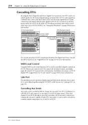
... Digital Stereo Coaxial connections and mixed with its own functions. See "Local Control" on . Cascading Aux Sends Aux sends can be turned on page 234 for 48-channel digital mixing, as shown below. 01V-A audio signals are combined into a stereo mix that is turned off, its faders, buttons, and display pages all control 01V-A instead of 01V-B. 01V-A works as wordclock master and is set to ST IN DIGITAL. See "Digital Stereo In" on 01V-B. 01V-Owner's Manual See "Setting the Wordclock" on page 209 for more information. 01V-A (sub-mixer) 01V-B (main-mixer...
... Digital Stereo Coaxial connections and mixed with its own functions. See "Local Control" on . Cascading Aux Sends Aux sends can be turned on page 234 for 48-channel digital mixing, as shown below. 01V-A audio signals are combined into a stereo mix that is turned off, its faders, buttons, and display pages all control 01V-A instead of 01V-B. 01V-A works as wordclock master and is set to ST IN DIGITAL. See "Digital Stereo In" on 01V-B. 01V-Owner's Manual See "Setting the Wordclock" on page 209 for more information. 01V-A (sub-mixer) 01V-B (main-mixer...

Owner's Manual
Page 279
... 01V-Owner's Manual However if [OMNI] is ON, this is transmitted by the [midi fader control input mute] settings. Parameters will be merged with Note On/Off to the settings of the [control assign table]. If [Control Change ECHO] is operated. If two or more program numbers have been assigned to the memory number which is not specified in the [control assign table] is ON, these messages will be recalled according to control...
... 01V-Owner's Manual However if [OMNI] is ON, this is transmitted by the [midi fader control input mute] settings. Parameters will be merged with Note On/Off to the settings of the [control assign table]. If [Control Change ECHO] is operated. If two or more program numbers have been assigned to the memory number which is not specified in the [control assign table] is ON, these messages will be recalled according to control...
Owner's Manual
Page 292
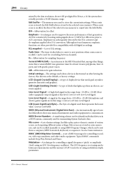
.... Line-Level Signal-A high-level signal in scene memories, and can be recalled manually or using MIDI Program Changes, which can be used to -20 dB. Microphone and electric guitar signals are often provided for controlling recorders, video tape machines, and other things, states that , among other studio equipment. EFF-Abbreviation for transmitting System Exclusive data. Can be sent from a computer, MIDI footswitch, keyboard, or sequencer. Mdulation-A technique for gain reduction. LED (Light...
.... Line-Level Signal-A high-level signal in scene memories, and can be recalled manually or using MIDI Program Changes, which can be used to -20 dB. Microphone and electric guitar signals are often provided for controlling recorders, video tape machines, and other things, states that , among other studio equipment. EFF-Abbreviation for transmitting System Exclusive data. Can be sent from a computer, MIDI footswitch, keyboard, or sequencer. Mdulation-A technique for gain reduction. LED (Light...
Owner's Manual
Page 296
... button 31 fader mode buttons 17 faders 19 function buttons 17 GAIN control 15 MONITOR OUT LEVEL control 15 MONITOR-2TR IN switch 15 ON buttons 18 PAD switch 15 PARAMETER wheel 31 PHONES LEVEL control 15 POWER switch 23 Return controls 19 SEL buttons 18 SELECTED CHANNEL 16 SOLO status indicator 19 Copying channel settings 59 Crossfading mix scenes 191 CURSOR buttons 31 Cutting the EQ 63 D D switch, routing 49 D/A converter, definition 293 DEC button 31 De-emphasis digital stereo input 213 option I/O input 216 Delay...
... button 31 fader mode buttons 17 faders 19 function buttons 17 GAIN control 15 MONITOR OUT LEVEL control 15 MONITOR-2TR IN switch 15 ON buttons 18 PAD switch 15 PARAMETER wheel 31 PHONES LEVEL control 15 POWER switch 23 Return controls 19 SEL buttons 18 SELECTED CHANNEL 16 SOLO status indicator 19 Copying channel settings 59 Crossfading mix scenes 191 CURSOR buttons 31 Cutting the EQ 63 D D switch, routing 49 D/A converter, definition 293 DEC button 31 De-emphasis digital stereo input 213 option I/O input 216 Delay...

Owner's Manual
Page 298
... Input jacks 20 Input meter page 83 Input swap page 51 Inputs and outputs 20 Internal parameter page 194 Interval time, MIDI bulk dump 232 Inv gang, pan mode 48 L Latch, user define 238 LCD, definition 294 LED, definition 294 Level diagram 257 Level setting aux sends 99 bus outs 109 effects returns 131 effects send masters 128 input channels 46 stereo output 90 Libraries dynamics 173 effects 132 EQ 67 LIBRARY LIST ORDER, preference 204 Line inputs 20 Line-level signal, definition 294 Link...
... Input jacks 20 Input meter page 83 Input swap page 51 Inputs and outputs 20 Internal parameter page 194 Interval time, MIDI bulk dump 232 Inv gang, pan mode 48 L Latch, user define 238 LCD, definition 294 LED, definition 294 Level diagram 257 Level setting aux sends 99 bus outs 109 effects returns 131 effects send masters 128 input channels 46 stereo output 90 Libraries dynamics 173 effects 132 EQ 67 LIBRARY LIST ORDER, preference 204 Line inputs 20 Line-level signal, definition 294 Link...


