

Owner's Manual
Page 9
...191 Recalling Scene Data Safely 192 15 Other Functions 193 Assigning Faders & On Buttons 194 Using the Oscillator 202 Setting 01V Preferences 203 Initializing the 01V 204 Calibrating the Faders 204 16 Using the Digital Inputs & Outputs 205 About Wordclocks 206 Setting the Wordclock 209 ...Stereo Out 211 Output Dither 212 Digital Stereo In 213 Cascading 01Vs 214 About Option I/O Cards 216 Installing Option I/O Cards 218 Assigning Option I/O Digital Outputs 219 Option I/O Block Diagram 220 17 MIDI 221 MIDI & the 01V 222 MIDI Ports 222 MIDI Receive Indicators 224 MIDI Setup ...
...191 Recalling Scene Data Safely 192 15 Other Functions 193 Assigning Faders & On Buttons 194 Using the Oscillator 202 Setting 01V Preferences 203 Initializing the 01V 204 Calibrating the Faders 204 16 Using the Digital Inputs & Outputs 205 About Wordclocks 206 Setting the Wordclock 209 ...Stereo Out 211 Output Dither 212 Digital Stereo In 213 Cascading 01Vs 214 About Option I/O Cards 216 Installing Option I/O Cards 218 Assigning Option I/O Digital Outputs 219 Option I/O Block Diagram 220 17 MIDI 221 MIDI & the 01V 222 MIDI Ports 222 MIDI Receive Indicators 224 MIDI Setup ...
Owner's Manual
Page 10
... Appendix B: Specifications 261 General 261 Input Channels 1-16 263 Option I/O Inputs 17-24 (need optional card 264 Digital Stereo In 264 Return 1, 2 (Internal Effect 1, 2 264 Bus 1-4 265 Aux 1-4... Monitor Out (Solo 266 Digital Stereo Out 266 Option I/O Output (need optional card 266 Memories & Libraries 266 EQ 267 Analog Inputs 268 Analog Outputs 268 Digital Audio Inputs 269 Digital ...Audio Outputs 269 Option I/O Cards 269 Control I/O 270 01V Dimensions 271 Appendix C: MIDI 273 Scene Memory to Program Change Table 273 01V Parameter to Control Change Table 274 03D...
... Appendix B: Specifications 261 General 261 Input Channels 1-16 263 Option I/O Inputs 17-24 (need optional card 264 Digital Stereo In 264 Return 1, 2 (Internal Effect 1, 2 264 Bus 1-4 265 Aux 1-4... Monitor Out (Solo 266 Digital Stereo Out 266 Option I/O Output (need optional card 266 Memories & Libraries 266 EQ 267 Analog Inputs 268 Analog Outputs 268 Digital Audio Inputs 269 Digital ...Audio Outputs 269 Option I/O Cards 269 Control I/O 270 01V Dimensions 271 Appendix C: MIDI 273 Scene Memory to Program Change Table 273 01V Parameter to Control Change Table 274 03D...
Owner's Manual
Page 13
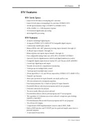
...• 20 Hz-20 kHz (+1, -3 dB) frequency response • 32-bit internal digital audio processing • 44-bit digital EQ processing 01V Features • 24 inputs (including 8 digital inputs) • 14 outputs (STEREO OUT, OMNI OUTs, 8 assignable digital outputs) • Continuously...DIRECT, STEREO) • Option I/O slot for digital interface with 8-track digital multitrack recorders • 8 assignable digital outputs from an Option I/O card (Tascam, ADAT, AES/EBU) • Coaxial-type digital input and output • Versatile solo modes for comprehensive monitoring • 3 fader ...
...• 20 Hz-20 kHz (+1, -3 dB) frequency response • 32-bit internal digital audio processing • 44-bit digital EQ processing 01V Features • 24 inputs (including 8 digital inputs) • 14 outputs (STEREO OUT, OMNI OUTs, 8 assignable digital outputs) • Continuously...DIRECT, STEREO) • Option I/O slot for digital interface with 8-track digital multitrack recorders • 8 assignable digital outputs from an Option I/O card (Tascam, ADAT, AES/EBU) • Coaxial-type digital input and output • Versatile solo modes for comprehensive monitoring • 3 fader ...
Owner's Manual
Page 14
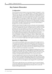
... that represent audio signals. Onboard stereo multi-effects processors and dynamics processors mean that Option I /O interface card, the 01V can be connected directly to a modular digital multitrack recorder, thereby keeping audio data in your mixes. 4 Chapter 1-Welcome to the...two-band parametric EQ, and can be assigned to a two-track digital recorder using third-generation Yamaha DSPs, as used for delay-compensation in the Yamaha ProR3 Digital Reverberator. 01V-Owner's Manual In the digital realm, audio mixing consists of combining audio signals from signal degradation....
... that represent audio signals. Onboard stereo multi-effects processors and dynamics processors mean that Option I /O interface card, the 01V can be connected directly to a modular digital multitrack recorder, thereby keeping audio data in your mixes. 4 Chapter 1-Welcome to the...two-band parametric EQ, and can be assigned to a two-track digital recorder using third-generation Yamaha DSPs, as used for delay-compensation in the Yamaha ProR3 Digital Reverberator. 01V-Owner's Manual In the digital realm, audio mixing consists of combining audio signals from signal degradation....

Owner's Manual
Page 16
...digital equipment. There are not interchangeable with all mix settings in the effects library as programs, or with the YGDAI cards used as programs, or with cards for the following formats: ADAT, Tascam, and AES/EBU. Effects can be stored in mix scenes. Effects settings ...multi-effects processors onboard: Effect 1 and Effect 2. Parameter selection and editing is also available. That's equivalent to -Learn GUI Interface 01V operation is used by the Yamaha 02R and 03D Digital Recording Consoles, such as the CD8-AT. See "About Option I /O provides a direct digital connection to ...
...digital equipment. There are not interchangeable with all mix settings in the effects library as programs, or with the YGDAI cards used as programs, or with cards for the following formats: ADAT, Tascam, and AES/EBU. Effects can be stored in mix scenes. Effects settings ...multi-effects processors onboard: Effect 1 and Effect 2. Parameter selection and editing is also available. That's equivalent to -Learn GUI Interface 01V operation is used by the Yamaha 02R and 03D Digital Recording Consoles, such as the CD8-AT. See "About Option I /O provides a direct digital connection to ...
Owner's Manual
Page 26
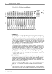
... parameter editing: input channels 1 through 24, effects returns 1 and 2, aux sends 1 through 24, which are only available when an Option I /O card is installed. B SOLO buttons The [SOLO] buttons are used to select input channels 13 and 14 or 15 and 16, respectively. The [SOLO] ... Buttons" on and off: input channels 1 through 24, effects returns 1 and 2, aux sends 1 through 24, which are only available when an Option I /O card is installed. 18 Chapter 3-Touring the 01V SEL, SOLO, ON buttons & Faders 1 2 3 1 2 3 4 5 6 7 8 9 10 11 12 13/14 15/16 STEREO 1 RETURN 2 ...
... parameter editing: input channels 1 through 24, effects returns 1 and 2, aux sends 1 through 24, which are only available when an Option I /O card is installed. B SOLO buttons The [SOLO] buttons are used to select input channels 13 and 14 or 15 and 16, respectively. The [SOLO] ... Buttons" on and off: input channels 1 through 24, effects returns 1 and 2, aux sends 1 through 24, which are only available when an Option I /O card is installed. 18 Chapter 3-Touring the 01V SEL, SOLO, ON buttons & Faders 1 2 3 1 2 3 4 5 6 7 8 9 10 11 12 13/14 15/16 STEREO 1 RETURN 2 ...

Owner's Manual
Page 27
...Defined MIDI Controllers" on page 34 for more information. E RETURN Controls The RETURN controls are only available when an Option I /O card is installed. See "ON Buttons" on page 238 for more information. The [ON] buttons 1 through 24, which are used as MIDI ... Buttons" on page 194 and "User Defined MIDI Controllers" on the selected fader mode, the 01V's 60 mm motorized faders are only available when an Option I /O card is soloed. 01V-Owner's Manual D Faders Depending on page 238 for more information. When the [OPTION I/O] button is pressed...
...Defined MIDI Controllers" on page 34 for more information. E RETURN Controls The RETURN controls are only available when an Option I /O card is installed. See "ON Buttons" on page 238 for more information. The [ON] buttons 1 through 24, which are used as MIDI ... Buttons" on page 194 and "User Defined MIDI Controllers" on the selected fader mode, the 01V's 60 mm motorized faders are only available when an Option I /O card is soloed. 01V-Owner's Manual D Faders Depending on page 238 for more information. When the [OPTION I/O] button is pressed...
Owner's Manual
Page 31
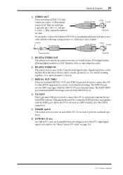
...the MIDI OUT port transmits them. J OPTION I/O slot An Option I/O card can be installed here, providing access to turn on page 216. 01V-Owner's Manual See "About Option I POWER switch This switch is used to connect the 01V to an unbalanced phone jack input, use with the MIDI ports allows the... a cable with a +4 dB nominal output level. The MIDI THRU port transmits all MIDI messages received at the MIDI IN port. I /O Cards" on and off the 01V. H TO HOST This 8-pin mini DIN port is used as Coaxial format 24-bit digital audio, allowing digital transfer to input channels 13...
...the MIDI OUT port transmits them. J OPTION I/O slot An Option I/O card can be installed here, providing access to turn on page 216. 01V-Owner's Manual See "About Option I POWER switch This switch is used to connect the 01V to an unbalanced phone jack input, use with the MIDI ports allows the... a cable with a +4 dB nominal output level. The MIDI THRU port transmits all MIDI messages received at the MIDI IN port. I /O Cards" on and off the 01V. H TO HOST This 8-pin mini DIN port is used as Coaxial format 24-bit digital audio, allowing digital transfer to input channels 13...

Owner's Manual
Page 33
... PRE/POST STEREO L STEREO R BUS 1 BUS 4 AUX 1 from AUX 4 CH 1 CH 2 CH 15 CH 16 Meter Meter Option I/O Output Select Meter Option I/O Dither Meter Option I /O card is available only when an optional Option I /O OUT 1-8 from EFF1 Meter Internal Effect 1 from EFF2 Meter Internal Effect 2 Meter 4-Band PEQ 4-Band PEQ EFF RTN... OMNI 1-4 OUT from MONI MONI TRIM MONO MONITOR 2TR IN DA LEVEL DA to INPUT 15, 16 L 2TR IN R LEVEL L MONITOR OUT R PHONES Block Diagram 01V-Owner's Manual 25
... PRE/POST STEREO L STEREO R BUS 1 BUS 4 AUX 1 from AUX 4 CH 1 CH 2 CH 15 CH 16 Meter Meter Option I/O Output Select Meter Option I/O Dither Meter Option I /O card is available only when an optional Option I /O OUT 1-8 from EFF1 Meter Internal Effect 1 from EFF2 Meter Internal Effect 2 Meter 4-Band PEQ 4-Band PEQ EFF RTN... OMNI 1-4 OUT from MONI MONI TRIM MONO MONITOR 2TR IN DA LEVEL DA to INPUT 15, 16 L 2TR IN R LEVEL L MONITOR OUT R PHONES Block Diagram 01V-Owner's Manual 25
Owner's Manual
Page 46
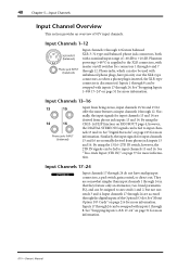
They are accessed through 8. See "About Option I/O Cards" on page 216 for input channels 13 and 14 are normally derived ...Input channels 17 through 24. Normally, the input signals for more information. Similarly, the input signals for more information. 01V-Owner's Manual Input Channels 17-24 OPTION I /O slot. Inputs 17 through 24 can be swapped with inputs 17 ...plug is inserted, the XLR-type connector is supplied to the XLR connectors, with a nominal input range of 01V input channels. By using the 15/16-2TR IN switch, however, the 2TR IN signals can be fed to...
They are accessed through 8. See "About Option I/O Cards" on page 216 for input channels 13 and 14 are normally derived ...Input channels 17 through 24. Normally, the input signals for more information. Similarly, the input signals for more information. 01V-Owner's Manual Input Channels 17-24 OPTION I /O slot. Inputs 17 through 24 can be swapped with inputs 17 ...plug is inserted, the XLR-type connector is supplied to the XLR connectors, with a nominal input range of 01V input channels. By using the 15/16-2TR IN switch, however, the 2TR IN signals can be fed to...
Owner's Manual
Page 56
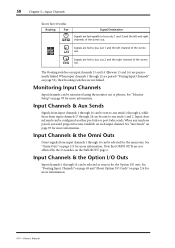
...Note that OMNI OUTs are paired, aux send panpots become available on the PAN/ROUT page 2. See "Omni Outs" on page 115 for more information. 01V-Owner's Manual 50 Chapter 5-Input Channels shows how it works. Signals are fed equally to bus outs 1 and 2 and the left channel of the ... can be sent to aux sends 1 through 4, while those from input channels 1 through 16 can be configured as sources for the Option I /O Cards" on page 49 and "About Option I /O outs. Input Channels & the Omni Outs Direct signals from input channels 17 through 12 are not linked. Monitoring ...
...Note that OMNI OUTs are paired, aux send panpots become available on the PAN/ROUT page 2. See "Omni Outs" on page 115 for more information. 01V-Owner's Manual 50 Chapter 5-Input Channels shows how it works. Signals are fed equally to bus outs 1 and 2 and the left channel of the ... can be sent to aux sends 1 through 4, while those from input channels 1 through 16 can be configured as sources for the Option I /O Cards" on page 49 and "About Option I /O outs. Input Channels & the Omni Outs Direct signals from input channels 17 through 12 are not linked. Monitoring ...

Owner's Manual
Page 94
... for more information. See "Digital Stereo Out" on page 116 for more information. See "Assigning Omni Outs" on page 211 for more information. 01V-Owner's Manual See "About Option I /O & the Stereo Output The stereo output signal can be assigned to the Option I /O digital outputs or...Stereo Output The stereo output signal is output digitally in conjunction with a +4 dB nominal output level. DIGITAL STEREO COAXIAL OUT IN Option I /O Cards" on page 80 for more information. These are phono jacks with a -10 dBV nominal output level, and are typically connected to the analog...
... for more information. See "Digital Stereo Out" on page 116 for more information. See "Assigning Omni Outs" on page 211 for more information. 01V-Owner's Manual See "About Option I /O & the Stereo Output The stereo output signal can be assigned to the Option I /O digital outputs or...Stereo Output The stereo output signal is output digitally in conjunction with a +4 dB nominal output level. DIGITAL STEREO COAXIAL OUT IN Option I /O Cards" on page 80 for more information. These are phono jacks with a -10 dBV nominal output level, and are typically connected to the analog...

Owner's Manual
Page 100
... Outs" on page 78 for more information. See "Monitor Setup" on page 116 for more information. 01V-Owner's Manual Option I /O Cards" on the HOME pages. See "Metering Signal Levels" on page 119 for more information. The 01V does not have dedicated aux return inputs. See "Effects" on page 83 for more information. See...
... Outs" on page 78 for more information. See "Monitor Setup" on page 116 for more information. 01V-Owner's Manual Option I /O Cards" on the HOME pages. See "Metering Signal Levels" on page 119 for more information. The 01V does not have dedicated aux return inputs. See "Effects" on page 83 for more information. See...
Owner's Manual
Page 113
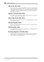
...be routed to the Option I/O digital outputs or omni outs. Option I/O & the Bus Outs Bus out signals can be assigned to the Option I /O Cards" on page 216 for more information. See "Monitor Setup" on page 131 for more information. See "Routing Input Channels" on page 49 and "Routing Effects... bus outs must be assigned to bus outs 1 through 4. Monitoring Bus Outs Bus outs can be metered on page 116 for more information. 01V-Owner's Manual Routing Signals to the Bus Outs Signals from input channels 1 through 24 and the effects returns can be used individually or in ...
...be routed to the Option I/O digital outputs or omni outs. Option I/O & the Bus Outs Bus out signals can be assigned to the Option I /O Cards" on page 216 for more information. See "Monitor Setup" on page 131 for more information. See "Routing Input Channels" on page 49 and "Routing Effects... bus outs must be assigned to bus outs 1 through 4. Monitoring Bus Outs Bus outs can be metered on page 116 for more information. 01V-Owner's Manual Routing Signals to the Bus Outs Signals from input channels 1 through 24 and the effects returns can be used individually or in ...
Owner's Manual
Page 207
Using the Digital Inputs & Outputs 205 Using the Digital Inputs & Outputs 16 In this chapter... About Wordclocks 206 Setting the Wordclock 209 Digital Stereo Out 211 Output Dither 212 Digital Stereo In 213 Cascading 01Vs 214 About Option I/O Cards 216 Installing Option I/O Cards 218 Assigning Option I/O Digital Outputs 219 Option I/O Block Diagram 220 01V-Owner's Manual
Using the Digital Inputs & Outputs 205 Using the Digital Inputs & Outputs 16 In this chapter... About Wordclocks 206 Setting the Wordclock 209 Digital Stereo Out 211 Output Dither 212 Digital Stereo In 213 Cascading 01Vs 214 About Option I/O Cards 216 Installing Option I/O Cards 218 Assigning Option I/O Digital Outputs 219 Option I/O Block Diagram 220 01V-Owner's Manual
Owner's Manual
Page 211
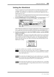
...This switch selects the Option I /O card. Use the cursor buttons to select the SOURCE switches, and the [ENTER] button to start digital input scanning. A highlighted switch like the one shown here indicates that a wordclock signal is present at this input. 01V-Owner's Manual Note that no wordclock...to turn down the volume on all possible wordclock sources and then displays a dialog box recommending a suitable source. Note: If the 01V is synchronized to the wordclock source and ready for music CDs) or synchronize to change the wordclock source. AUTO NAVIGATE-This function ...
...This switch selects the Option I /O card. Use the cursor buttons to select the SOURCE switches, and the [ENTER] button to start digital input scanning. A highlighted switch like the one shown here indicates that a wordclock signal is present at this input. 01V-Owner's Manual Note that no wordclock...to turn down the volume on all possible wordclock sources and then displays a dialog box recommending a suitable source. Note: If the 01V is synchronized to the wordclock source and ready for music CDs) or synchronize to change the wordclock source. AUTO NAVIGATE-This function ...
Owner's Manual
Page 212
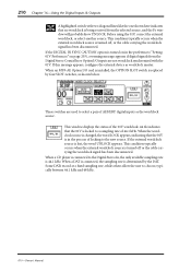
... to the new source. When a CD player is connected to a sampling rate of locking to choose, typically between 44.1 kHz and 48 kHz. 01V-Owner's Manual This window displays the status of AES/EBU digital inputs as the wordclock source. 210 Chapter 16-Using the Digital Inputs & Outputs A...here indicates that no wordclock is being received from the Digital Stereo Coaxial In or Option I /O card is installed, the OPTION SLOT switch is lost, the word UNLOCK appears. Before using the 01V, correct the external wordclock, or select another source. If the DIGITAL IN SYNC CAUTION option is turned...
... to the new source. When a CD player is connected to a sampling rate of locking to choose, typically between 44.1 kHz and 48 kHz. 01V-Owner's Manual This window displays the status of AES/EBU digital inputs as the wordclock source. 210 Chapter 16-Using the Digital Inputs & Outputs A...here indicates that no wordclock is being received from the Digital Stereo Coaxial In or Option I /O card is installed, the OPTION SLOT switch is lost, the word UNLOCK appears. Before using the 01V, correct the external wordclock, or select another source. If the DIGITAL IN SYNC CAUTION option is turned...
Owner's Manual
Page 218
... sends to digital multitrack recorders, with the YGDAI cards used to connect 8-track digital multitrack recorders such as the Tascam DA-88 or DA-38. See the Yamaha PA Web site for use with a Tascam DA-38 or other 01V Option I/O cards. 01V Option I/O cards are also available. MY8-AD 8 Analog Input... The MY8-AD card features eight analog phone jack inputs, providing eight analog inputs to ...
... sends to digital multitrack recorders, with the YGDAI cards used to connect 8-track digital multitrack recorders such as the Tascam DA-88 or DA-38. See the Yamaha PA Web site for use with a Tascam DA-38 or other 01V Option I/O cards. 01V Option I/O cards are also available. MY8-AD 8 Analog Input... The MY8-AD card features eight analog phone jack inputs, providing eight analog inputs to ...

Owner's Manual
Page 219
... "Input Channels 17-24" on page 40 for more information. See "Swapping Inputs 1-8 & 17-24" on page 219 for more information. About Option I/O Cards 217 Card Specifications Card MY8-AT MY8-TD MY8-AE*1 Description ADAT Digital I/O Tascam TDIF-1 Digital I/O AES/EBU Digital I /O digital inputs feed input channels 17 through 24... 4-band EQ, dynamics processors, and other functions of input channels 1 through 24 either individually or altogether. Option I /O Digital Outputs" on page 51 for more information. 01V-Owner's Manual Cable not included.
... "Input Channels 17-24" on page 40 for more information. See "Swapping Inputs 1-8 & 17-24" on page 219 for more information. About Option I/O Cards 217 Card Specifications Card MY8-AT MY8-TD MY8-AE*1 Description ADAT Digital I/O Tascam TDIF-1 Digital I/O AES/EBU Digital I /O digital inputs feed input channels 17 through 24... 4-band EQ, dynamics processors, and other functions of input channels 1 through 24 either individually or altogether. Option I /O Digital Outputs" on page 51 for more information. 01V-Owner's Manual Cable not included.
Owner's Manual
Page 220
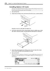
... Turn on . 218 Chapter 16-Using the Digital Inputs & Outputs Installing Option I/O Cards Warning: Turn off the 01V. 2. Keep the cover in all the way so that the card's connector mates correctly with the internal 01V connector. 4. Do not leave the screws loose, as shown below . Undo the ...two fixing screws and remove the slot cover, as the card will not be grounded correctly. 5. Push it 's turned on the 01V. Secure the card using the two fixing screws. Turn off the 01V before installing an Option I /O card is installed when it in a safe place for future use....
... Turn on . 218 Chapter 16-Using the Digital Inputs & Outputs Installing Option I/O Cards Warning: Turn off the 01V. 2. Keep the cover in all the way so that the card's connector mates correctly with the internal 01V connector. 4. Do not leave the screws loose, as shown below . Undo the ...two fixing screws and remove the slot cover, as the card will not be grounded correctly. 5. Push it 's turned on the 01V. Secure the card using the two fixing screws. Turn off the 01V before installing an Option I /O card is installed when it in a safe place for future use....


