Installation Instructions
Page 1
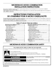
... reduce the chance of injury, and tell you and others are not followed. Table of Contents / Table des matières MICROWAVE HOOD COMBINATION SAFETY 1 INSTALLATION REQUIREMENTS 2 Tools and Parts 2 Remove Cardboard Template 2 Location Requirements 2 Product Dimensions 3 Electrical Requirements...'t immediately follow instructions. This symbol alerts you to Wall 8 Prepare Upper Cabinet 8 Install Damper Assembly 9 Install the Microwave Oven 9 Complete Installation 10 VENTING DESIGN SPECIFICATIONS 11 ASSISTANCE 12 Replacement Parts 12 Accessories 12 SÉCURITÉ DE ...
... reduce the chance of injury, and tell you and others are not followed. Table of Contents / Table des matières MICROWAVE HOOD COMBINATION SAFETY 1 INSTALLATION REQUIREMENTS 2 Tools and Parts 2 Remove Cardboard Template 2 Location Requirements 2 Product Dimensions 3 Electrical Requirements...'t immediately follow instructions. This symbol alerts you to Wall 8 Prepare Upper Cabinet 8 Install Damper Assembly 9 Install the Microwave Oven 9 Complete Installation 10 VENTING DESIGN SPECIFICATIONS 11 ASSISTANCE 12 Replacement Parts 12 Accessories 12 SÉCURITÉ DE ...
Installation Instructions
Page 2
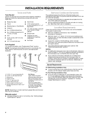
.... See User Instructions.) NOTE: Depending on model, charcoal filters may be free of clearance between the wall and the microwave oven, so that the materials used will be included. Location Requirements Check the opening . ■ Support for cabinet ... section. Special Requirements For Wall Venting Installation Only: ■ Cutout must provide: ■ Minimum installation dimensions. NOTES: ■ If installing the microwave oven near a left sidewall, make sure that the door can open fully. ■ Some cabinet and building materials are for cooking. A B ...
.... See User Instructions.) NOTE: Depending on model, charcoal filters may be free of clearance between the wall and the microwave oven, so that the materials used will be included. Location Requirements Check the opening . ■ Support for cabinet ... section. Special Requirements For Wall Venting Installation Only: ■ Cutout must provide: ■ Minimum installation dimensions. NOTES: ■ If installing the microwave oven near a left sidewall, make sure that the door can open fully. ■ Some cabinet and building materials are for cooking. A B ...
Installation Instructions
Page 3
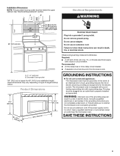
... The grounded 3 prong outlet must be plugged into a grounded 3 prong outlet. Do not use an adapter. Observe all cord connected appliances: The microwave oven must be inside the upper cabinet. Recommended: ■ A time-delay fuse or time-delay circuit breaker. ■ A separate circuit serving only this... cm) min. 30" (76.2 cm) min. 30" (76.2 cm) typical* 12" (30.5 cm) min. 14" (35.6 cm) max. Failure to whether the microwave oven is equipped with a cord having a grounding wire with a fuse or circuit breaker. In the event of an electrical short circuit, grounding reduces the risk...
... The grounded 3 prong outlet must be plugged into a grounded 3 prong outlet. Do not use an adapter. Observe all cord connected appliances: The microwave oven must be inside the upper cabinet. Recommended: ■ A time-delay fuse or time-delay circuit breaker. ■ A separate circuit serving only this... cm) min. 30" (76.2 cm) min. 30" (76.2 cm) typical* 12" (30.5 cm) min. 14" (35.6 cm) max. Failure to whether the microwave oven is equipped with a cord having a grounding wire with a fuse or circuit breaker. In the event of an electrical short circuit, grounding reduces the risk...
Installation Instructions
Page 4
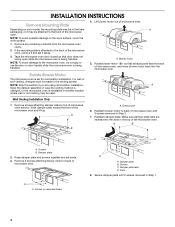
... Slots 8. NOTE: To avoid possible damage to top of the microwave oven. Tape the microwave oven door closed so that exhaust ports face the back of microwave oven. Blower motor 5. Rotate Blower Motor The microwave oven is being handled. Remove screws attaching damper plate to the...blower motor back into the slots in Step 1. 4 A B A. Lift blower motor out of the microwave oven and lift up. NOTE: Skip this section if you are inserted into the microwave oven. Damper plate 2. A A. Damper plate tabs D. Secure damper plate with 2 screws removed in ...
... Slots 8. NOTE: To avoid possible damage to top of the microwave oven. Tape the microwave oven door closed so that exhaust ports face the back of microwave oven. Blower motor 5. Rotate Blower Motor The microwave oven is being handled. Remove screws attaching damper plate to the...blower motor back into the slots in Step 1. 4 A B A. Lift blower motor out of the microwave oven and lift up. NOTE: Skip this section if you are inserted into the microwave oven. Damper plate 2. A A. Damper plate tabs D. Secure damper plate with 2 screws removed in ...
Installation Instructions
Page 5
..., and flat sides of blower motor face back of "Wall Venting Installation Only." Reattach blower motor to the microwave oven. 7. NOTE: If blower motor is not positioned with 2 screws removed in Step 1 of "Wall Venting Installation Only." 5 A B C A. Damper plate tabs D. Repeat... Step 4 from "Wall Venting Installation Only." 2. Lower blower motor back into the slots in the top of the microwave oven (as shown), performance will be reattached to back of microwave oven with 2 screws removed in Step 3 cannot be poor. Securely tighten screws. Make sure damper plate tabs are ...
..., and flat sides of blower motor face back of "Wall Venting Installation Only." Reattach blower motor to the microwave oven. 7. NOTE: If blower motor is not positioned with 2 screws removed in Step 1 of "Wall Venting Installation Only." 5 A B C A. Damper plate tabs D. Repeat... Step 4 from "Wall Venting Installation Only." 2. Lower blower motor back into the slots in the top of the microwave oven (as shown), performance will be reattached to back of microwave oven with 2 screws removed in Step 3 cannot be poor. Securely tighten screws. Make sure damper plate tabs are ...
Installation Instructions
Page 6
... Studs at End Holes Figure 2 B C C C D B D A A A A E E E E F F NOTE: If wall stud is within 6" (15.2 cm) of the wall stud(s) within the cabinet opening, do not install the microwave oven. 1. Support tabs F. Using a stud finder, locate the edges of the vertical centerline (see "Mark Rear Wall" section), only recirculation or roof venting installation can...
... Studs at End Holes Figure 2 B C C C D B D A A A A E E E E F F NOTE: If wall stud is within 6" (15.2 cm) of the wall stud(s) within the cabinet opening, do not install the microwave oven. 1. Support tabs F. Using a stud finder, locate the edges of the vertical centerline (see "Mark Rear Wall" section), only recirculation or roof venting installation can...
Installation Instructions
Page 7
... marks made in "Locate Wall Stud(s)" section. 7 Refer to complete the 12" x 4" (30.5 x 10.2 cm) rectangle. Set the mounting plate aside. Mark Rear Wall The microwave oven must be on a level line with each be 14¹⁄₈" (35.9 cm) from the centerline. 5. Make sure the mounting plate is the...
... marks made in "Locate Wall Stud(s)" section. 7 Refer to complete the 12" x 4" (30.5 x 10.2 cm) rectangle. Set the mounting plate aside. Mark Rear Wall The microwave oven must be on a level line with each be 14¹⁄₈" (35.9 cm) from the centerline. 5. Make sure the mounting plate is the...
Installation Instructions
Page 8
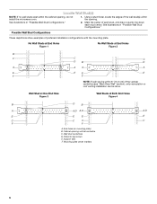
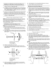
... space for the toggle nut to go through the drywall, and finger tighten the bolts to use as guides. ■ If the wall behind the microwave oven (as at both end holes. 3. Spring toggle nut 3. C A 6. Start a toggle nut on a second wall stud, drill a 3/16" (5 mm) hole into...Step 6 of mounting plate. 2. B D A. 1/4-20 x 3" round-head bolt B. Installation for Wall Stud at One End Hole (Figure 3) 1. With the support tabs of the microwave oven. B A C A. 1/4-20 x 3" round-head bolt B. Push the 2 bolts with the holes in the top of the mounting plate facing forward, insert 1/4-20 x 3" ...
... space for the toggle nut to go through the drywall, and finger tighten the bolts to use as guides. ■ If the wall behind the microwave oven (as at both end holes. 3. Spring toggle nut 3. C A 6. Start a toggle nut on a second wall stud, drill a 3/16" (5 mm) hole into...Step 6 of mounting plate. 2. B D A. 1/4-20 x 3" round-head bolt B. Installation for Wall Stud at One End Hole (Figure 3) 1. With the support tabs of the microwave oven. B A C A. 1/4-20 x 3" round-head bolt B. Push the 2 bolts with the holes in the top of the mounting plate facing forward, insert 1/4-20 x 3" ...
Installation Instructions
Page 9
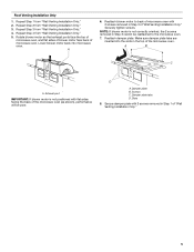
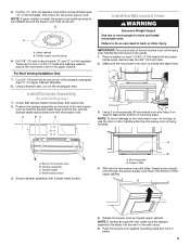
... the vent in the bottom of mounting plate. NOTE: If venting through the power supply cord hole in the wall cutout. 6. Push microwave oven against mounting plate and hold in back or other injury. Cut the 1¹⁄₂" (3.8 cm) diameter hole at the bottom...only) 1. A. Secure damper assembly with 2 sheet metal screws. B A A. Power supply cord bushing 6. A B C D Install the Microwave Oven WARNING Excessive Weight Hazard Use two or more people, lift microwave oven and hang it on each 1/4-20 x 3" flat-head bolt and place inside upper cabinet near the 3/8" (10 mm) holes...
... the vent in the bottom of mounting plate. NOTE: If venting through the power supply cord hole in the wall cutout. 6. Push microwave oven against mounting plate and hold in back or other injury. Cut the 1¹⁄₂" (3.8 cm) diameter hole at the bottom...only) 1. A. Secure damper assembly with 2 sheet metal screws. B A A. Power supply cord bushing 6. A B C D Install the Microwave Oven WARNING Excessive Weight Hazard Use two or more people, lift microwave oven and hang it on each 1/4-20 x 3" flat-head bolt and place inside upper cabinet near the 3/8" (10 mm) holes...
Installation Instructions
Page 10
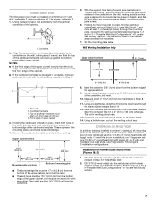
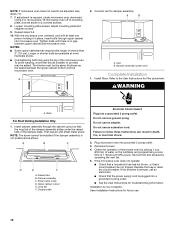
... as shown. A B A. Refer to the User Instructions for troubleshooting information. A B C D E F A. Raised tabs B. Long tab F. Check the operation of microwave oven by operating the vent fan. 5. If the problem continues, call an electrician. ■ Check that the power supply cord is not positioned as the...prong. Test vent fan and exhaust by placing 1 cup (250 mL) of the damper assembly slides under vent) Complete Installation 1. If the microwave oven does not operate: ■ Check that a household fuse has not blown, or that the long tab of water on a covered surface...
... as shown. A B A. Refer to the User Instructions for troubleshooting information. A B C D E F A. Raised tabs B. Long tab F. Check the operation of microwave oven by operating the vent fan. 5. If the problem continues, call an electrician. ■ Check that the power supply cord is not positioned as the...prong. Test vent fan and exhaust by placing 1 cup (250 mL) of the damper assembly slides under vent) Complete Installation 1. If the microwave oven does not operate: ■ Check that a household fuse has not blown, or that the long tab of water on a covered surface...
Installation Instructions
Page 11
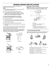
...or garages. Roof cap B. 6" (15.2 cm) min. diameter round vent C. Vent extension piece, at least 3" (7.6 cm) of clearance between the top of the microwave oven and the rectangular to Round Transition" illustration. Wall cap E. 3¹⁄₄" x 10" to 6" (8.3 x 25.4 cm to 15.2 cm) rectangular to ...is used, be sure there is at least 3" (7.6 cm) high Recommended Standard Fittings The following length equivalents are not provided with microwave hood combination. ■ We do not recommend using a flexible metal vent. ■ To avoid possible product damage, be sure ...
...or garages. Roof cap B. 6" (15.2 cm) min. diameter round vent C. Vent extension piece, at least 3" (7.6 cm) of clearance between the top of the microwave oven and the rectangular to Round Transition" illustration. Wall cap E. 3¹⁄₄" x 10" to 6" (8.3 x 25.4 cm to 15.2 cm) rectangular to ...is used, be sure there is at least 3" (7.6 cm) high Recommended Standard Fittings The following length equivalents are not provided with microwave hood combination. ■ We do not recommend using a flexible metal vent. ■ To avoid possible product damage, be sure ...
Installation Instructions
Page 12
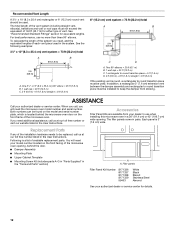
... or roof caps must not exceed the equivalent of 140 ft (42.7 m) for equivalent lengths. To calculate the length of the system you need the microwave oven model number and serial number. Two 90° elbows = 20 ft (6.1 m) B. 1 wall cap = 40 ft (12.2 m) C. 1... = 8 ft (2.4 m) 6" (15.2 cm) vent system = 73 ft (22.2 m) total A B 6 ft (1.8 m) 2 ft (0.6 m) C D A. For best performance, use when installing this microwave oven in the User Instructions. Accessories Filler Panel Kits are available from sticking. Following is round, a rectangular to use no more than three 90°...
... or roof caps must not exceed the equivalent of 140 ft (42.7 m) for equivalent lengths. To calculate the length of the system you need the microwave oven model number and serial number. Two 90° elbows = 20 ft (6.1 m) B. 1 wall cap = 40 ft (12.2 m) C. 1... = 8 ft (2.4 m) 6" (15.2 cm) vent system = 73 ft (22.2 m) total A B 6 ft (1.8 m) 2 ft (0.6 m) C D A. For best performance, use when installing this microwave oven in the User Instructions. Accessories Filler Panel Kits are available from sticking. Following is round, a rectangular to use no more than three 90°...


