Installation Instructions
Page 1
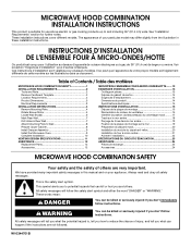
...section "Exigences d'installation" pour d'autres remarques. This symbol alerts you to and including 36" (91.4 cm) wide. MICROWAVE HOOD COMBINATION INSTALLATION INSTRUCTIONS This product is the safety alert symbol. Il se peut que l'apparence de votre propre mod&#...hazards that can be killed or seriously injured if you don't immediately follow instructions. Table of Contents / Table des matières MICROWAVE HOOD COMBINATION SAFETY 1 INSTALLATION REQUIREMENTS 2 Tools and Parts 2 Remove Cardboard Template 2 Location Requirements 2 Product Dimensions 3 Electrical Requirements 3...
...section "Exigences d'installation" pour d'autres remarques. This symbol alerts you to and including 36" (91.4 cm) wide. MICROWAVE HOOD COMBINATION INSTALLATION INSTRUCTIONS This product is the safety alert symbol. Il se peut que l'apparence de votre propre mod&#...hazards that can be killed or seriously injured if you don't immediately follow instructions. Table of Contents / Table des matières MICROWAVE HOOD COMBINATION SAFETY 1 INSTALLATION REQUIREMENTS 2 Tools and Parts 2 Remove Cardboard Template 2 Location Requirements 2 Product Dimensions 3 Electrical Requirements 3...
Installation Instructions
Page 2
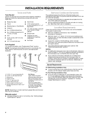
... perforation is for cooking. See User Instructions.) NOTE: Depending on model, charcoal filters may be combined. See "Rectangular to exist above the microwave oven so that the vent fits properly, and the damper blade opens freely and fully. Toggle nuts (2) E. 1/4" x 2" lag screws... (2) F. Materials needed ■ Standard fittings for weight of the microwave oven packaging is at least 6" (15.2 cm) of packaging) Aluminum grease filters Charcoal filters (Depending on model, aluminum grease filter and ...
... perforation is for cooking. See User Instructions.) NOTE: Depending on model, charcoal filters may be combined. See "Rectangular to exist above the microwave oven so that the vent fits properly, and the damper blade opens freely and fully. Toggle nuts (2) E. 1/4" x 2" lag screws... (2) F. Materials needed ■ Standard fittings for weight of the microwave oven packaging is at least 6" (15.2 cm) of packaging) Aluminum grease filters Charcoal filters (Depending on model, aluminum grease filter and ...
Installation Instructions
Page 3
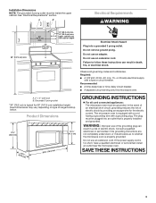
...min. 30" (76.2 cm) min. 30" (76.2 cm) typical* 12" (30.5 cm) min. 14" (35.6 cm) max. Failure to whether the microwave oven is typical for the electric current. Grounded 3 prong outlet *30" (76.2 cm) is properly grounded. WARNING: Improper use an extension cord. If the power... be inside the upper cabinet. Recommended: ■ A time-delay fuse or time-delay circuit breaker. ■ A separate circuit serving only this microwave oven. SAVE THESE INSTRUCTIONS 3 Exact dimensions may vary depending on type of electric shock by providing an escape wire for 66" (167.6 cm) ...
...min. 30" (76.2 cm) min. 30" (76.2 cm) typical* 12" (30.5 cm) min. 14" (35.6 cm) max. Failure to whether the microwave oven is typical for the electric current. Grounded 3 prong outlet *30" (76.2 cm) is properly grounded. WARNING: Improper use an extension cord. If the power... be inside the upper cabinet. Recommended: ■ A time-delay fuse or time-delay circuit breaker. ■ A separate circuit serving only this microwave oven. SAVE THESE INSTRUCTIONS 3 Exact dimensions may vary depending on type of electric shock by providing an escape wire for 66" (167.6 cm) ...
Installation Instructions
Page 4
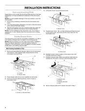
...your model, the mounting plate may be in Step 1. 4 Remove any remaining contents from the microwave oven cavity. 2. Tape the microwave oven door closed so that exhaust ports face the back of microwave oven, and lower blower motor back into the slots in another location where wall or roof ...motor 5. A Keep the damper assembly in case the venting method is changed, or the microwave oven is reinstalled in the top of the microwave oven. Remove screws attaching damper plate to back of the microwave oven and lift up. Keep damper plate and screws together and set it aside. 3. If...
...your model, the mounting plate may be in Step 1. 4 Remove any remaining contents from the microwave oven cavity. 2. Tape the microwave oven door closed so that exhaust ports face the back of microwave oven, and lower blower motor back into the slots in another location where wall or roof ...motor 5. A Keep the damper assembly in case the venting method is changed, or the microwave oven is reinstalled in the top of the microwave oven. Remove screws attaching damper plate to back of the microwave oven and lift up. Keep damper plate and screws together and set it aside. 3. If...
Installation Instructions
Page 5
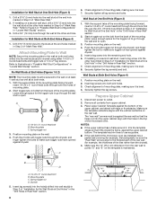
Rotate blower motor so that exhaust ports face the top of microwave oven, and flat sides of blower motor face back of the microwave oven (as shown), performance will be reattached to the microwave oven. 7. Exhaust port IMPORTANT: If blower motor is not ... damper plate. Repeat Step 4 from "Wall Venting Installation Only." 2. A B C A. D A. Screws C. Make sure damper plate tabs are inserted into microwave oven. Damper plate B. Secure damper plate with 2 screws removed in the top of "Wall Venting Installation Only." 5 NOTE: If blower motor is not positioned...
Rotate blower motor so that exhaust ports face the top of microwave oven, and flat sides of blower motor face back of the microwave oven (as shown), performance will be reattached to the microwave oven. 7. Exhaust port IMPORTANT: If blower motor is not ... damper plate. Repeat Step 4 from "Wall Venting Installation Only." 2. A B C A. D A. Screws C. Make sure damper plate tabs are inserted into microwave oven. Damper plate B. Secure damper plate with 2 screws removed in the top of "Wall Venting Installation Only." 5 NOTE: If blower motor is not positioned...
Installation Instructions
Page 6
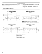
End holes (on mounting plate) B. Wall stud centerlines D. Support tabs F. Cabinet opening , do not install the microwave oven. 1. Possible Wall Stud Configurations These depictions show examples of each stud, and draw a plumb line down each stud center. Wall Stud at One End ...
End holes (on mounting plate) B. Wall stud centerlines D. Support tabs F. Cabinet opening , do not install the microwave oven. 1. Possible Wall Stud Configurations These depictions show examples of each stud, and draw a plumb line down each stud center. Wall Stud at One End ...
Installation Instructions
Page 7
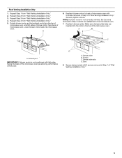
... of the upper cabinet. Drill 3/4" (19 mm) holes through the marks made in one 1/4-20 x 3" round-head bolt with toggle nut; Mark Rear Wall The microwave oven must align with front edge of cabinet. Using measuring tape, find the wall stud centerline(s) drawn in Step 3, and that the top of the...
... of the upper cabinet. Drill 3/4" (19 mm) holes through the marks made in one 1/4-20 x 3" round-head bolt with toggle nut; Mark Rear Wall The microwave oven must align with front edge of cabinet. Using measuring tape, find the wall stud centerline(s) drawn in Step 3, and that the top of the...
Installation Instructions
Page 8
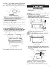
... the template centerline aligns with the vertical centerline on the template is level. 4. Make sure the 10" (25.4 cm) dimension from the back of the microwave oven. B D A. 1/4-20 x 3" round-head bolt B. Spring toggle nut D. Drill a 3/4" (19 mm) hole through the wall and to illustrations in "Possible Wall Stud ...the top of the mounting plate. Check alignment of the mounting plate. Disconnect power to use as guides. ■ If the wall behind the microwave oven (as at One End Hole" in the "Drill Holes in Step 3 of the upper cabinet, and attach with toggle nut through the...
... the template centerline aligns with the vertical centerline on the template is level. 4. Make sure the 10" (25.4 cm) dimension from the back of the microwave oven. B D A. 1/4-20 x 3" round-head bolt B. Spring toggle nut D. Drill a 3/4" (19 mm) hole through the wall and to illustrations in "Possible Wall Stud ...the top of the mounting plate. Check alignment of the mounting plate. Disconnect power to use as guides. ■ If the wall behind the microwave oven (as at One End Hole" in the "Drill Holes in Step 3 of the upper cabinet, and attach with toggle nut through the...
Installation Instructions
Page 9
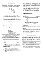
...easily into the vent in the bottom of mounting plate. B A A. Install Damper Assembly (for the power supply cord. Make sure the microwave oven door is for wall venting only) 1. Damper assembly C. This hole is closed and taped shut. 3. Power supply cord bushing 6. For... Roof Venting Installation Only 7. IMPORTANT: The control side of microwave oven B. Place a washer on support tabs at points "D" and "E" on the template. Secure damper assembly with 2 sheet metal screws. A. NOTE: If...
...easily into the vent in the bottom of mounting plate. B A A. Install Damper Assembly (for the power supply cord. Make sure the microwave oven door is for wall venting only) 1. Damper assembly C. This hole is closed and taped shut. 3. Power supply cord bushing 6. For... Roof Venting Installation Only 7. IMPORTANT: The control side of microwave oven B. Place a washer on support tabs at points "D" and "E" on the template. Secure damper assembly with 2 sheet metal screws. A. NOTE: If...
Installation Instructions
Page 10
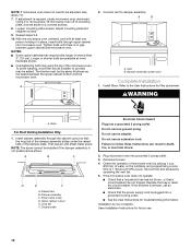
...problem continues, call an electrician. ■ Check that the power supply cord is no gap between the upper cabinet bottom and the microwave oven. If adjustment is now complete. Refer to damper assembly. Damper assembly C. Damper plate Electrical Shock Hazard Plug into grounded 3 ...steps 3-6. 10. Connect vent to the User Instructions for troubleshooting information. Do not use an adapter. Installation is required, rotate microwave oven downward. To avoid warping, wood filler blocks (installer to follow these instructions can result in place, insert bolts through the ...
...problem continues, call an electrician. ■ Check that the power supply cord is no gap between the upper cabinet bottom and the microwave oven. If adjustment is now complete. Refer to damper assembly. Damper assembly C. Damper plate Electrical Shock Hazard Plug into grounded 3 ...steps 3-6. 10. Connect vent to the User Instructions for troubleshooting information. Do not use an adapter. Installation is required, rotate microwave oven downward. To avoid warping, wood filler blocks (installer to follow these instructions can result in place, insert bolts through the ...
Installation Instructions
Page 11
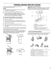
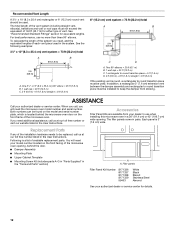
...; elbow: 6" = 10 ft (15.2 cm = 3 m) E. Rectangular to Round Transition NOTE: The minimum 3" (7.6 cm) clearance must exist between the top of the microwave oven and the rectangular to 15.2 cm = 1.5 m) B. Vent extension piece, at least 3" (7.6 cm) of clearance between the top of the...VENTING DESIGN SPECIFICATIONS This section is at least 3" (7.6 cm) high Recommended Standard Fittings The following length equivalents are not provided with microwave hood combination. ■ We do not recommend using recirculation installation. Elbow (for the damper to round transition is used, be...
...; elbow: 6" = 10 ft (15.2 cm = 3 m) E. Rectangular to Round Transition NOTE: The minimum 3" (7.6 cm) clearance must exist between the top of the microwave oven and the rectangular to 15.2 cm = 1.5 m) B. Vent extension piece, at least 3" (7.6 cm) of clearance between the top of the...VENTING DESIGN SPECIFICATIONS This section is at least 3" (7.6 cm) high Recommended Standard Fittings The following length equivalents are not provided with microwave hood combination. ■ We do not recommend using recirculation installation. Elbow (for the damper to round transition is used, be...
Installation Instructions
Page 12
... Cabinet Template ■ Mounting Screw Kit (includes parts A-G in "Parts Supplied" in pairs. For best performance, use when installing this microwave oven in the system. ASSISTANCE Call your dealer to use no more than three 90° elbows. Filler panels Filler Panel Kit Number ...8171339 99403 White Black Biscuit Stainless Steel Almond See your model number located on the front frame of the system you need the microwave oven model number and serial number. In addition, a rectangular 3" (7.6 cm) extension vent between the damper assembly and rectangular to...
... Cabinet Template ■ Mounting Screw Kit (includes parts A-G in "Parts Supplied" in pairs. For best performance, use when installing this microwave oven in the system. ASSISTANCE Call your dealer to use no more than three 90° elbows. Filler panels Filler Panel Kit Number ...8171339 99403 White Black Biscuit Stainless Steel Almond See your model number located on the front frame of the system you need the microwave oven model number and serial number. In addition, a rectangular 3" (7.6 cm) extension vent between the damper assembly and rectangular to...


