Installation Instructions
Page 1
... You can happen if the instructions are very important. This is suitable for use above electric or gas cooking products up to Wall 9 Install the Microwave Oven 9 Complete Installation 10 VENTING DESIGN SPECIFICATIONS 11 ASSISTANCE 12 Replacement Parts 12 MICROWAVE HOOD COMBINATION SAFETY Your safety and the safety of Contents MICROWAVE HOOD...
... You can happen if the instructions are very important. This is suitable for use above electric or gas cooking products up to Wall 9 Install the Microwave Oven 9 Complete Installation 10 VENTING DESIGN SPECIFICATIONS 11 ASSISTANCE 12 Replacement Parts 12 MICROWAVE HOOD COMBINATION SAFETY Your safety and the safety of Contents MICROWAVE HOOD...
Installation Instructions
Page 2
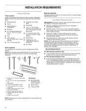
... Location Requirements IMPORTANT: Check the opening . ■■ Support for wall or ro venting) J. The location must be combined. 2 See the "Installation Dimensions" illustration. ■■ Minimum one 2" x 4" (5.1 cm x 10.16 cm) wood wall stud and minimum 3/8" (9.5 mm) thickness... drywall or plaster/lath within cabinet opening where the microwave oven will not discolor, delaminate, or sustain other types of wall structures, be installed. Sheet metal screws 5/32" x 5/16" (0.4 cm x 0.8 cm) (2) G. Damper assembly (for weight of any tools listed here. ■...
... Location Requirements IMPORTANT: Check the opening . ■■ Support for wall or ro venting) J. The location must be combined. 2 See the "Installation Dimensions" illustration. ■■ Minimum one 2" x 4" (5.1 cm x 10.16 cm) wood wall stud and minimum 3/8" (9.5 mm) thickness... drywall or plaster/lath within cabinet opening where the microwave oven will not discolor, delaminate, or sustain other types of wall structures, be installed. Sheet metal screws 5/32" x 5/16" (0.4 cm x 0.8 cm) (2) G. Damper assembly (for weight of any tools listed here. ■...
Installation Instructions
Page 3
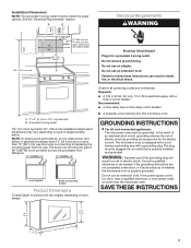
... the event of an electrical short circuit, grounding reduces the risk of electric shock by providing an escape wire for 60" (152.4 cm) installation height exact dimensions may vary depending on door design. WARNING: Improper use an extension cord. A. 2" x 4" (5.1 cm x 10.1 cm... the bump out mounting kit replacing the mounting plate from Whirlpool. 12" DEEPER 14" 14" DEEPER 15" mounting plate Bump out mounting bracket Product Dimensions *Overall depth of electric shock. See the "Electrical Requirements" section. Installation Dimensions NOTE: The grounded 3 prong outlet must be plugged...
... the event of an electrical short circuit, grounding reduces the risk of electric shock by providing an escape wire for 60" (152.4 cm) installation height exact dimensions may vary depending on door design. WARNING: Improper use an extension cord. A. 2" x 4" (5.1 cm x 10.1 cm... the bump out mounting kit replacing the mounting plate from Whirlpool. 12" DEEPER 14" 14" DEEPER 15" mounting plate Bump out mounting bracket Product Dimensions *Overall depth of electric shock. See the "Electrical Requirements" section. Installation Dimensions NOTE: The grounded 3 prong outlet must be plugged...
Installation Instructions
Page 4
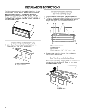
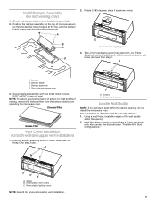
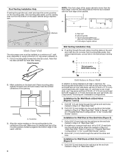
... screws 5/32" x 5/16" (4 mm x 8 mm). Slide damper plate toward the front of microwave oven B. Damper plate 4 Install Damper Assembly (for recirculation installation. Check that the damper blade hinge is at the top, and the damper blade opens away from the microwave oven. Damper blade D. Remove... freely, and opens fully. 2. Screws B. Damper vent covers A. Sheet metal screw 5/32" x 5/16" (4 mm x 8 mm) 3. A B A. Roof Venting Installation Only 1. A B A. Using diagonal wire cutting pliers, gently snip out the rectangular vent cover on the back of microwave oven exterior...
... screws 5/32" x 5/16" (4 mm x 8 mm). Slide damper plate toward the front of microwave oven B. Damper plate 4 Install Damper Assembly (for recirculation installation. Check that the damper blade hinge is at the top, and the damper blade opens away from the microwave oven. Damper blade D. Remove... freely, and opens fully. 2. Screws B. Damper vent covers A. Sheet metal screw 5/32" x 5/16" (4 mm x 8 mm) 3. A B A. Roof Venting Installation Only 1. A B A. Using diagonal wire cutting pliers, gently snip out the rectangular vent cover on the back of microwave oven exterior...
Installation Instructions
Page 5
...blade C. NOTE: To ensure good performance of airflow, for Wall and Roof venting, remove the charcoal filter from step 1. Keep C for future recirculation vent installation. 5 See illustrations in "Possible Wall Stud Configurations." Using a stud finder, locate the edges of the wall stud(s) within the cabinet opening . 2. Recirculation...microwave oven 3. Slide them as shown below with two sheet metal screws 5/32" x 5/16" (4 mm x 8 mm). Screws B. Install Damper Assembly (for both of them out. Check that the damper blade hinge is at the top, and the damper blade opens away ...
...blade C. NOTE: To ensure good performance of airflow, for Wall and Roof venting, remove the charcoal filter from step 1. Keep C for future recirculation vent installation. 5 See illustrations in "Possible Wall Stud Configurations." Using a stud finder, locate the edges of the wall stud(s) within the cabinet opening . 2. Recirculation...microwave oven 3. Slide them as shown below with two sheet metal screws 5/32" x 5/16" (4 mm x 8 mm). Screws B. Install Damper Assembly (for both of them out. Check that the damper blade hinge is at the top, and the damper blade opens away ...
Installation Instructions
Page 6
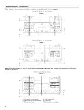
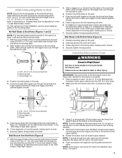
... be done. Wall Studs at End Holes Figure 2 B C A A REAR WALL REAR WALL E E D F NOTE: If wall studs is within 6" (15.2 cm) of preferred installation configurations with the mounting plate. Support tabs F. End holes (on mounting plate) B. Holes for lag screws E. Cabinet opening vertical centerline C. Wall stud centerlines D. Mounting plate ...
... be done. Wall Studs at End Holes Figure 2 B C A A REAR WALL REAR WALL E E D F NOTE: If wall studs is within 6" (15.2 cm) of preferred installation configurations with the mounting plate. Support tabs F. End holes (on mounting plate) B. Holes for lag screws E. Cabinet opening vertical centerline C. Wall stud centerlines D. Mounting plate ...
Installation Instructions
Page 7
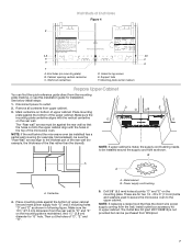
...the bottom of upper cabinet line and mark power supply hole "G" and 2 mounting holes "D" and "E" as installed) has a partial wall covering (for example, tile backslash), be purchased from Whirlpool. 7 A. NOTE: If replacing a range hood that the holes cut the holes of the rear wall (for... lag screws E. Cabinet opening vertical centerline C. Wall stud centerlines D. The "Rear wall" arrows must be installed around the supply cord hole as ...
...the bottom of upper cabinet line and mark power supply hole "G" and 2 mounting holes "D" and "E" as installed) has a partial wall covering (for example, tile backslash), be purchased from Whirlpool. 7 A. NOTE: If replacing a range hood that the holes cut the holes of the rear wall (for... lag screws E. Cabinet opening vertical centerline C. Wall stud centerlines D. The "Rear wall" arrows must be installed around the supply cord hole as ...
Installation Instructions
Page 8
...: If the front edge of the upper cabinet is lower than the back edge, lower the mounting plate so that the tabs will NOT be installed on a second wall stud, drill a 3/16" (5 mm) hole into the tab cutout. Top of mounting plate must be flush after folding. A1 Cut-out area... at One End Hole (Figure 3) 1. if 1 end hole is butted up against the back wall, find and clearly mark the vertical centerline of the opening. Installation for BACK WALL Venting A2 B1 B2 Drill Holes in Rear Wall In addition to the centerline of "Mark Rear Wall." 2. Drill 5/8" (1.6 cm) holes through...
...: If the front edge of the upper cabinet is lower than the back edge, lower the mounting plate so that the tabs will NOT be installed on a second wall stud, drill a 3/16" (5 mm) hole into the tab cutout. Top of mounting plate must be flush after folding. A1 Cut-out area... at One End Hole (Figure 3) 1. if 1 end hole is butted up against the back wall, find and clearly mark the vertical centerline of the opening. Installation for BACK WALL Venting A2 B1 B2 Drill Holes in Rear Wall In addition to the centerline of "Mark Rear Wall." 2. Drill 5/8" (1.6 cm) holes through...
Installation Instructions
Page 9
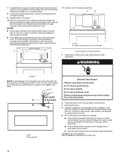
...Push microwave oven against drywall. 5. Refer to illustrations in "Possible Wall Stud Configurations" in Step 2 of the mounting plate. For fast wall and roof vent installation, see the quick reference guide on each 1/4-20 x 3" (7.6 cm) flat-head bolt and place inside upper cabinet near the 3/8" (9.5 mm) holes. 2.... Drywall 5. Wall Stud at One End Hole" in the "Drill Holes in Rear Wall" section. 3. Using 2 or more people to move and install microwave oven. With front of mounting plate, making sure it is being handled. 4. No Wall Studs at End Holes (Figures 1 and 2) NOTE:...
...Push microwave oven against drywall. 5. Refer to illustrations in "Possible Wall Stud Configurations" in Step 2 of the mounting plate. For fast wall and roof vent installation, see the quick reference guide on each 1/4-20 x 3" (7.6 cm) flat-head bolt and place inside upper cabinet near the 3/8" (9.5 mm) holes. 2.... Drywall 5. Wall Stud at One End Hole" in the "Drill Holes in Rear Wall" section. 3. Using 2 or more people to move and install microwave oven. With front of mounting plate, making sure it is being handled. 4. No Wall Studs at End Holes (Figures 1 and 2) NOTE:...
Installation Instructions
Page 10
... power. 4. Repeat steps 3 through upper cabinet into microwave oven. Install filters. Do not use an extension cord. Loosen mounting plate screws. To avoid warping, wood filler blocks (installer to follow these instructions can result in place, insert bolts through ...6. 10. Vent B. Damper assembly (under vent) Compact A Complete Installation 1. WARNING A. Do not use an adapter. Save Installation Instructions for filter placement. Failure to provide) may require bolts longer or shorter than 3" (7.6 cm). ...
... power. 4. Repeat steps 3 through upper cabinet into microwave oven. Install filters. Do not use an extension cord. Loosen mounting plate screws. To avoid warping, wood filler blocks (installer to follow these instructions can result in place, insert bolts through ...6. 10. Vent B. Damper assembly (under vent) Compact A Complete Installation 1. WARNING A. Do not use an adapter. Save Installation Instructions for filter placement. Failure to provide) may require bolts longer or shorter than 3" (7.6 cm). ...
Installation Instructions
Page 11
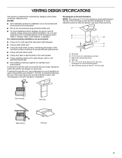
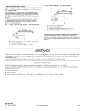
...performance If venting through the roof, and rectangular-to open freely and fully. Roof cap B. 6" (15.2 cm) min. For optimal venting installation, we recommend: ■■ Using roof or wall caps that have back draft dampers ■■ Using a rigid metal vent ■■... seal all joints in the vent system ■■ Using caulking compound to seal exterior wall or roof opening around cap ■■ Not installing 2 elbows together for installation are at least 3" (7.6 cm) high Roof venting Roof cap Wall venting Wall cap 11 A B C D E 3" (7.6 cm) F A. ...
...performance If venting through the roof, and rectangular-to open freely and fully. Roof cap B. 6" (15.2 cm) min. For optimal venting installation, we recommend: ■■ Using roof or wall caps that have back draft dampers ■■ Using a rigid metal vent ■■... seal all joints in the vent system ■■ Using caulking compound to seal exterior wall or roof opening around cap ■■ Not installing 2 elbows together for installation are at least 3" (7.6 cm) high Roof venting Roof cap Wall venting Wall cap 11 A B C D E 3" (7.6 cm) F A. ...
Installation Instructions
Page 12
.... See the "Recommended Standard Fittings" section for either type of the vent system including straight vent, elbow(s), transitions, and wall or roof caps must be installed to -round transition piece must be used . When you call us at our toll-free number listed in the User Guide. Following is located behind... number plate, which is a list of the system you will need , add the equivalent lengths of the microwave oven. Replacement Parts If any of the installation hardware needs to -round transition piece = 5 ft (1.5 m) D. 2 ft (0.6 m) + 6 ft (1.8 m) straight = 8 ft (2.4 m) 2 ft...
.... See the "Recommended Standard Fittings" section for either type of the vent system including straight vent, elbow(s), transitions, and wall or roof caps must be installed to -round transition piece must be used . When you call us at our toll-free number listed in the User Guide. Following is located behind... number plate, which is a list of the system you will need , add the equivalent lengths of the microwave oven. Replacement Parts If any of the installation hardware needs to -round transition piece = 5 ft (1.5 m) D. 2 ft (0.6 m) + 6 ft (1.8 m) straight = 8 ft (2.4 m) 2 ft...
Owners Manual
Page 1
... on your microwave oven at www.whirlpool.com. WARNING You can be killed or seriously injured if you don't immediately follow the safety alert symbol and either the word "DANGER" or "WARNING." I Read all safety messages. I Install or locate the microwave oven only...instructions are not followed. IMPORTANT SAFETY INSTRUCTIONS When using the microwave oven. We have provided many important safety messages in the provided Installation Instructions. This symbol alerts you to excessive microwave energy: I Read and follow instructions. I The microwave oven must be grounded. ...
... on your microwave oven at www.whirlpool.com. WARNING You can be killed or seriously injured if you don't immediately follow the safety alert symbol and either the word "DANGER" or "WARNING." I Read all safety messages. I Install or locate the microwave oven only...instructions are not followed. IMPORTANT SAFETY INSTRUCTIONS When using the microwave oven. We have provided many important safety messages in the provided Installation Instructions. This symbol alerts you to excessive microwave energy: I Read and follow instructions. I The microwave oven must be grounded. ...
Owners Manual
Page 3
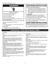
...60 Hz, AC-only, 15 or 20 amp electrical supply with Part 18 of electric shock by providing an escape wire for language is properly installed and grounded. Recommended: ■■ A time-delay fuse or time-delay circuit breaker. ■■ A separate circuit serving only this keypad...1. Electrical Requirements WARNING GROUNDING INSTRUCTIONS Electrical Shock Hazard Plug into an outlet that is selected you'll have a qualified electrician or serviceman install an outlet near the microwave oven. Do not remove ground prong. Do not use an extension cord. Do not use of the ...
...60 Hz, AC-only, 15 or 20 amp electrical supply with Part 18 of electric shock by providing an escape wire for language is properly installed and grounded. Recommended: ■■ A time-delay fuse or time-delay circuit breaker. ■■ A separate circuit serving only this keypad...1. Electrical Requirements WARNING GROUNDING INSTRUCTIONS Electrical Shock Hazard Plug into an outlet that is selected you'll have a qualified electrician or serviceman install an outlet near the microwave oven. Do not remove ground prong. Do not use an extension cord. Do not use of the ...
Owners Manual
Page 6
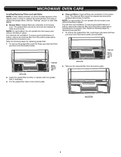
... is time to replace the charcoal filter, and clean or replace the grease filters. Refer the following steps for replacing grease filter: 1. MICROWAVE OVEN CARE Installing/Replacing Filters and Light Bulbs NOTE: A Filter Status indicator (on some models) appears in place. The grease filters should be removed and cleaned at least...
... is time to replace the charcoal filter, and clean or replace the grease filters. Refer the following steps for replacing grease filter: 1. MICROWAVE OVEN CARE Installing/Replacing Filters and Light Bulbs NOTE: A Filter Status indicator (on some models) appears in place. The grease filters should be removed and cleaned at least...
Owners Manual
Page 10
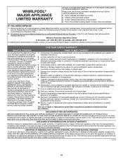
...Removal or reinstallation of purchase, 1. WHIRLPOOL® MAJOR APPLIANCE LIMITED WARRANTY ATTACH YOUR RECEIPT HERE. If outside the 50 United States or Canada, contact your appliance will pay for in materials and workmanship and is installed, installation instructions. ONE YEAR LIMITED WARRANTY WHAT...major appliance was purchased. Some states and provinces do not allow limitations on how to correct improper product maintenance or installation, installation not in this limited warranty. 14. Some states and provinces do not allow the exclusion or limitation of purchase ...
...Removal or reinstallation of purchase, 1. WHIRLPOOL® MAJOR APPLIANCE LIMITED WARRANTY ATTACH YOUR RECEIPT HERE. If outside the 50 United States or Canada, contact your appliance will pay for in materials and workmanship and is installed, installation instructions. ONE YEAR LIMITED WARRANTY WHAT...major appliance was purchased. Some states and provinces do not allow limitations on how to correct improper product maintenance or installation, installation not in this limited warranty. 14. Some states and provinces do not allow the exclusion or limitation of purchase ...


