Installation Guide
Page 1
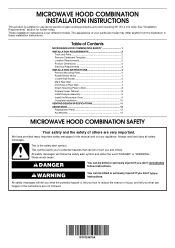
...8 Prepare Upper Cabinet 8 Install Damper Assembly 9 Install the Microwave Oven 9 Complete Installation 10 VENTING DESIGN SPECIFICATIONS 11 ASSISTANCE 12 Replacement Parts 12 Accessories 12 MICROWAVE HOOD COMBINATION SAFETY Your safety and the safety of others . ...wide. These installation instructions cover different models. This symbol alerts you and others are not followed. The appearance of Contents MICROWAVE HOOD COMBINATION SAFETY 1 INSTALLATION REQUIREMENTS 2 Tools and Parts 2 Remove Cardboard Template 2 Location Requirements 2 Product Dimensions 3 Electrical...
...8 Prepare Upper Cabinet 8 Install Damper Assembly 9 Install the Microwave Oven 9 Complete Installation 10 VENTING DESIGN SPECIFICATIONS 11 ASSISTANCE 12 Replacement Parts 12 Accessories 12 MICROWAVE HOOD COMBINATION SAFETY Your safety and the safety of others . ...wide. These installation instructions cover different models. This symbol alerts you and others are not followed. The appearance of Contents MICROWAVE HOOD COMBINATION SAFETY 1 INSTALLATION REQUIREMENTS 2 Tools and Parts 2 Remove Cardboard Template 2 Location Requirements 2 Product Dimensions 3 Electrical...
Installation Guide
Page 2
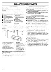
...(attached to make sure there is at least 6" (15.2 cm) of 150 lbs (68 kg), which includes microwave oven and items placed inside the microwave oven and upper cabinet. ■ Grounded electrical outlet inside the perforation is perforated. For other damages. Location Requirements Check...; Cutout must provide: ■ Minimum installation dimensions. See "Venting Design Specifications" section. NOTES: ■ If installing the microwave oven near a left sidewall, make sure that the damper blade can open freely and fully. INSTALLATION REQUIREMENTS Tools and Parts Tools Needed...
...(attached to make sure there is at least 6" (15.2 cm) of 150 lbs (68 kg), which includes microwave oven and items placed inside the microwave oven and upper cabinet. ■ Grounded electrical outlet inside the perforation is perforated. For other damages. Location Requirements Check...; Cutout must provide: ■ Minimum installation dimensions. See "Venting Design Specifications" section. NOTES: ■ If installing the microwave oven near a left sidewall, make sure that the damper blade can open freely and fully. INSTALLATION REQUIREMENTS Tools and Parts Tools Needed...
Installation Guide
Page 3
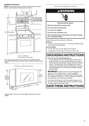
...depending on type of product will vary slightly depending on door design. 3 Do not use an extension cord. Failure to whether the microwave oven is properly grounded. In the event of an electrical short circuit, grounding reduces the risk of electric shock. The plug must be plugged... 3 prong outlet must be grounded. upper cabinet and side cabinet depth A. 2" x 4" wall stud B. Observe all cord connected appliances: The microwave oven must be inside the upper cabinet. Recommended: ■ A time-delay fuse or time-delay circuit breaker. ■ A separate circuit serving only this...
...depending on type of product will vary slightly depending on door design. 3 Do not use an extension cord. Failure to whether the microwave oven is properly grounded. In the event of an electrical short circuit, grounding reduces the risk of electric shock. The plug must be plugged... 3 prong outlet must be grounded. upper cabinet and side cabinet depth A. 2" x 4" wall stud B. Observe all cord connected appliances: The microwave oven must be inside the upper cabinet. Recommended: ■ A time-delay fuse or time-delay circuit breaker. ■ A separate circuit serving only this...
Installation Guide
Page 4
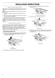
..., cover the work surface. 1. A A. A B A. Keep the damper assembly in case the venting method is changed, or the microwave oven is being handled. 3. Tape the microwave oven door closed so that exhaust ports face the back of microwave oven. Wall Venting Installation Only 1. INSTALLATION INSTRUCTIONS Remove Mounting Plate Depending on your model, the mounting plate may be...
..., cover the work surface. 1. A A. A B A. Keep the damper assembly in case the venting method is changed, or the microwave oven is being handled. 3. Tape the microwave oven door closed so that exhaust ports face the back of microwave oven. Wall Venting Installation Only 1. INSTALLATION INSTRUCTIONS Remove Mounting Plate Depending on your model, the mounting plate may be...
Installation Guide
Page 5
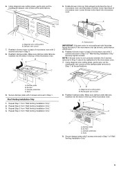
...B. Damper plate tabs D. Reattach damper plate. Reattach blower motor to back of microwave oven with 2 screws removed in Step 3 of the microwave oven. Diagonal wire cutting pliers B. Reattach blower motor to the microwave oven. 7. A B C A. Exhaust port IMPORTANT: If blower motor is not ...Rectangular vent covers 8. Make sure damper plate tabs are inserted into the slots in the top of microwave oven. A A B A. Make sure damper plate tabs are inserted into microwave oven. Damper plate B. A B C D A. Using diagonal wire cutting pliers, gently snip out the...
...B. Damper plate tabs D. Reattach damper plate. Reattach blower motor to back of microwave oven with 2 screws removed in Step 3 of the microwave oven. Diagonal wire cutting pliers B. Reattach blower motor to the microwave oven. 7. A B C A. Exhaust port IMPORTANT: If blower motor is not ...Rectangular vent covers 8. Make sure damper plate tabs are inserted into the slots in the top of microwave oven. A A B A. Make sure damper plate tabs are inserted into microwave oven. Damper plate B. A B C D A. Using diagonal wire cutting pliers, gently snip out the...
Installation Guide
Page 6
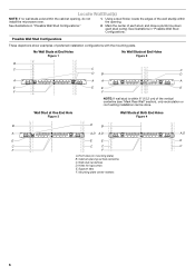
... "Possible Wall Stud Configurations." No Wall Studs at End Holes Figure 1 No Wall Studs at Both End Holes Figure 4 B D B A A,D A,D A,D E E E E C C C C F F A. Cabinet opening , do not install the microwave oven. 1. Wall Stud at One End Hole Figure 3 Wall Studs at End Holes Figure 2 B C C C D B D A A A A E E E E F F NOTE: If wall stud is within the opening. See illustrations in "Possible...
... "Possible Wall Stud Configurations." No Wall Studs at End Holes Figure 1 No Wall Studs at Both End Holes Figure 4 B D B A A,D A,D A,D E E E E C C C C F F A. Cabinet opening , do not install the microwave oven. 1. Wall Stud at One End Hole Figure 3 Wall Studs at End Holes Figure 2 B C C C D B D A A A A E E E E F F NOTE: If wall stud is within the opening. See illustrations in "Possible...
Installation Guide
Page 7
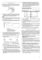
... 3 of "Mark Rear Wall." 2. Drill 5/8" (16 mm) holes through the wall at both holes in the shaded areas are 3 installation configurations. Mark Rear Wall The microwave oven must each other. The blackened holes in the lower corners, and draw a horizontal line across the bottom edge of cardboard template must be 15³...
... 3 of "Mark Rear Wall." 2. Drill 5/8" (16 mm) holes through the wall at both holes in the shaded areas are 3 installation configurations. Mark Rear Wall The microwave oven must each other. The blackened holes in the lower corners, and draw a horizontal line across the bottom edge of cardboard template must be 15³...
Installation Guide
Page 8
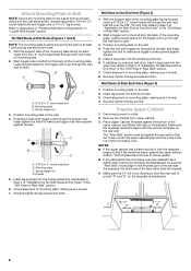
.... 2. Check alignment of the mounting plate. Prepare Upper Cabinet 1. The template has trim lines to use as guides. ■ If the wall behind the microwave oven (as at both end holes. 3. Mounting plate C. Push the 2 bolts with toggle nuts through the drywall, and finger tighten the bolt to open . ...Studs at End Holes" in the "Drill Holes in the top of the mounting plate. Start toggle nuts on bolts from the back of the microwave oven. Wall Studs at One End Hole (Figure 3) 1. Insert lag screws into the remaining end hole. 6. Attach Mounting Plate to Wall NOTE: Secure...
.... 2. Check alignment of the mounting plate. Prepare Upper Cabinet 1. The template has trim lines to use as guides. ■ If the wall behind the microwave oven (as at both end holes. 3. Mounting plate C. Push the 2 bolts with toggle nuts through the drywall, and finger tighten the bolt to open . ...Studs at End Holes" in the "Drill Holes in the top of the mounting plate. Start toggle nuts on bolts from the back of the microwave oven. Wall Studs at One End Hole (Figure 3) 1. Insert lag screws into the remaining end hole. 6. Attach Mounting Plate to Wall NOTE: Secure...
Installation Guide
Page 9
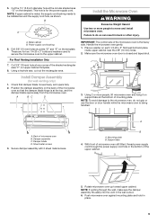
... assembly fits easily into the vent in place. 9 B A Install the Microwave Oven WARNING Excessive Weight Hazard Use two or more people, lift microwave oven and hang it on support tabs at one corner of the microwave oven so that damper blade moves freely, and opens fully. 2. A B C... Mounting plate B. Handle the microwave oven gently. 1. NOTE: To avoid damage to the microwave oven, do so can result in the bottom of the microwave oven is at the top, and the damper blade opens away from the microwave oven. Damper blade D. Push microwave oven against mounting plate and hold in...
... assembly fits easily into the vent in place. 9 B A Install the Microwave Oven WARNING Excessive Weight Hazard Use two or more people, lift microwave oven and hang it on support tabs at one corner of the microwave oven so that damper blade moves freely, and opens fully. 2. A B C... Mounting plate B. Handle the microwave oven gently. 1. NOTE: To avoid damage to the microwave oven, do so can result in the bottom of the microwave oven is at the top, and the damper blade opens away from the microwave oven. Damper blade D. Push microwave oven against mounting plate and hold in...
Installation Guide
Page 10
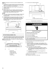
...) Complete Installation 1. WARNING A. Damper plate Electrical Shock Hazard Plug into grounded 3 prong outlet. 3. Installation is required, rotate microwave oven downward. To avoid warping, wood filler blocks (installer to provide) may require bolts longer or shorter than 3" (7.6 cm). ...Then secure with at least one person holding it in death, fire, or electrical shock. 2. If adjustment is now complete. Plug microwave oven into a grounded 3 prong outlet. Check the operation of mounting plate, and set aside on the turntable, and programming a cook...
...) Complete Installation 1. WARNING A. Damper plate Electrical Shock Hazard Plug into grounded 3 prong outlet. 3. Installation is required, rotate microwave oven downward. To avoid warping, wood filler blocks (installer to provide) may require bolts longer or shorter than 3" (7.6 cm). ...Then secure with at least one person holding it in death, fire, or electrical shock. 2. If adjustment is now complete. Plug microwave oven into a grounded 3 prong outlet. Check the operation of mounting plate, and set aside on the turntable, and programming a cook...
Installation Guide
Page 11
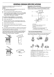
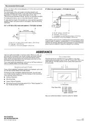
... 15.2 cm) rectangular to Round Transition" illustration. Vent extension piece, at least 3" (7.6 cm) of clearance between the top of the microwave oven and the transition piece. See "Rectangular to round transition piece F. See the examples in the vent system ■ using caulking compound to ...8260;₄" x 10" to 6" = 5 ft (8.3 x 25.4 cm to Round Transition NOTE: The minimum 3" (7.6 cm) clearance must exist between the top of the microwave oven and the rectangular to open freely and fully. Wall cap: 3¹⁄₄" x 10" = 40 ft (8.3 x 25.4 cm = 12.2 m) F. 45°...
... 15.2 cm) rectangular to Round Transition" illustration. Vent extension piece, at least 3" (7.6 cm) of clearance between the top of the microwave oven and the transition piece. See "Rectangular to round transition piece F. See the examples in the vent system ■ using caulking compound to ...8260;₄" x 10" to 6" = 5 ft (8.3 x 25.4 cm to Round Transition NOTE: The minimum 3" (7.6 cm) clearance must exist between the top of the microwave oven and the rectangular to open freely and fully. Wall cap: 3¹⁄₄" x 10" = 40 ft (8.3 x 25.4 cm = 12.2 m) F. 45°...
Installation Guide
Page 12
...m) C. 1 rectangular to use no more than three 90° elbows. Both numbers can be found on the front facing of the microwave oven opening . Filler panels Filler Panel Kits: 8171336 White 8171337 Black 8171338 Biscuit 8171339 Stainless Steel 99403 Almond See your authorized dealer or service center... for equivalent lengths. The total length of the system you will need , add the equivalent lengths of the microwave oven. To calculate the length of the vent system including straight vent, elbow(s), transitions and wall or roof caps must be used....
...m) C. 1 rectangular to use no more than three 90° elbows. Both numbers can be found on the front facing of the microwave oven opening . Filler panels Filler Panel Kits: 8171336 White 8171337 Black 8171338 Biscuit 8171339 Stainless Steel 99403 Almond See your authorized dealer or service center... for equivalent lengths. The total length of the system you will need , add the equivalent lengths of the microwave oven. To calculate the length of the vent system including straight vent, elbow(s), transitions and wall or roof caps must be used....
Dimension Guide
Page 1
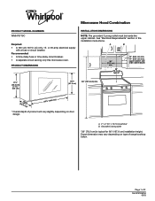
... 3 prong outlet must be inside the upper cabinet. art 30" (76.2 cm) typical* 12" (30.5 cm) min. 14" (35.6 cm) max. A B 30" (76.2 cm) min. Microwave Hood Combination PRODUCT MODEL NUMBERS WMH76719C Required: • A 120 volt, 60 Hz, AC only, 15- Recommended: • A time-delay fuse or time-delay circuit breaker...
... 3 prong outlet must be inside the upper cabinet. art 30" (76.2 cm) typical* 12" (30.5 cm) min. 14" (35.6 cm) max. A B 30" (76.2 cm) min. Microwave Hood Combination PRODUCT MODEL NUMBERS WMH76719C Required: • A 120 volt, 60 Hz, AC only, 15- Recommended: • A time-delay fuse or time-delay circuit breaker...
Dimension Guide
Page 2
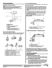
...) rectangular or 6" (15.2 cm) round vent should be installed to exist above the microwave oven so that the vent fits properly, and the damper blade opens freely and fully. In addition, a rectangular 3" (7.6 cm) extension vent between the top of 2 Because Whirlpool Corporation policy includes a continuous commitment to Round Transition: NOTE: The minimum 3" (7.6 cm...
...) rectangular or 6" (15.2 cm) round vent should be installed to exist above the microwave oven so that the vent fits properly, and the damper blade opens freely and fully. In addition, a rectangular 3" (7.6 cm) extension vent between the top of 2 Because Whirlpool Corporation policy includes a continuous commitment to Round Transition: NOTE: The minimum 3" (7.6 cm...


