Installation Guide
Page 1
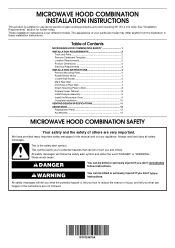
... INSTRUCTIONS 4 Remove Mounting Plate 4 Rotate Blower Motor 4 Locate Wall Stud(s 6 Mark Rear Wall 7 Drill Holes in these installation instructions. W10724870A These words mean: DANGER You can be killed or seriously injured if you don't follow instructions. See "Installation Requirements" section for use above electric or gas cooking products up to Wall 8 Prepare Upper Cabinet 8 Install Damper Assembly 9 Install the Microwave Oven 9 Complete Installation 10 VENTING DESIGN SPECIFICATIONS 11 ASSISTANCE 12 Replacement Parts 12 Accessories 12 MICROWAVE HOOD COMBINATION...
... INSTRUCTIONS 4 Remove Mounting Plate 4 Rotate Blower Motor 4 Locate Wall Stud(s 6 Mark Rear Wall 7 Drill Holes in these installation instructions. W10724870A These words mean: DANGER You can be killed or seriously injured if you don't follow instructions. See "Installation Requirements" section for use above electric or gas cooking products up to Wall 8 Prepare Upper Cabinet 8 Install Damper Assembly 9 Install the Microwave Oven 9 Complete Installation 10 VENTING DESIGN SPECIFICATIONS 11 ASSISTANCE 12 Replacement Parts 12 Accessories 12 MICROWAVE HOOD COMBINATION...
Installation Guide
Page 2
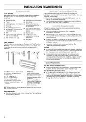
... opening . ■ Support for cooking. See "Electrical Requirements" section. Check with any obstructions so that the materials used will be free of packaging) Aluminum grease filters Charcoal filters (Depending on model, charcoal filters may be included. Washers (2) D. 3/16" toggle nuts (2) E. 1/4" x 2" lag screws (2) F. The piece inside upper cabinet. Cut along the perforation to Round Transition" illustration in "Venting Design Specifications" section. 2 See "Installation Dimensions" illustration. ■ Minimum one 2" x 4" (50.8 x 101.6 mm) wood wall...
... opening . ■ Support for cooking. See "Electrical Requirements" section. Check with any obstructions so that the materials used will be free of packaging) Aluminum grease filters Charcoal filters (Depending on model, charcoal filters may be included. Washers (2) D. 3/16" toggle nuts (2) E. 1/4" x 2" lag screws (2) F. The piece inside upper cabinet. Cut along the perforation to Round Transition" illustration in "Venting Design Specifications" section. 2 See "Installation Dimensions" illustration. ■ Minimum one 2" x 4" (50.8 x 101.6 mm) wood wall...
Installation Guide
Page 3
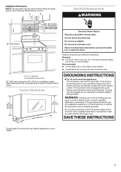
... electrician or serviceman install an outlet near the microwave oven. Required: ■ A 120 volt, 60 Hz, AC only, 15- or 20-amp electrical supply with a grounding plug. upper cabinet and side cabinet depth A. 2" x 4" wall stud B. Do not use an extension cord. Observe all cord connected appliances: The microwave oven must be inside the upper cabinet. GROUNDING INSTRUCTIONS ■ For all governing codes and ordinances. Product Dimensions 17¹...
... electrician or serviceman install an outlet near the microwave oven. Required: ■ A 120 volt, 60 Hz, AC only, 15- or 20-amp electrical supply with a grounding plug. upper cabinet and side cabinet depth A. 2" x 4" wall stud B. Do not use an extension cord. Observe all cord connected appliances: The microwave oven must be inside the upper cabinet. GROUNDING INSTRUCTIONS ■ For all governing codes and ordinances. Product Dimensions 17¹...
Installation Guide
Page 4
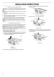
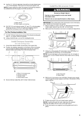
... microwave oven. Remove 2 screws attaching blower motor to the back of the microwave oven and lift up. A A. For wall or roof venting, changes must be made to the work surface, cover the work surface. 1. Slide damper plate toward the front of the microwave oven, remove it and set it may be used. Exhaust port A. If the mounting plate is being handled. 3. Screws (in recessed holes) 4. Damper plate 2. Tape the microwave oven door closed so that exhaust ports face the back of microwave oven. A A. INSTALLATION INSTRUCTIONS Remove Mounting Plate...
... microwave oven. Remove 2 screws attaching blower motor to the back of the microwave oven and lift up. A A. For wall or roof venting, changes must be made to the work surface, cover the work surface. 1. Slide damper plate toward the front of the microwave oven, remove it and set it may be used. Exhaust port A. If the mounting plate is being handled. 3. Screws (in recessed holes) 4. Damper plate 2. Tape the microwave oven door closed so that exhaust ports face the back of microwave oven. A A. INSTALLATION INSTRUCTIONS Remove Mounting Plate...
Installation Guide
Page 5
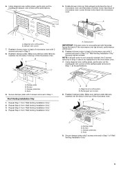
... screws removed in Step 3 of the microwave oven. D A. AB A. Reattach damper plate. Reattach damper plate. Diagonal wire cutting pliers B. Rectangular vent covers 8. Slots 9. Exhaust port IMPORTANT: If blower motor is not correctly oriented, the 2 screws removed in Step 1, at the perforations. 5. Repeat Step 3 from "Wall Venting Installation Only." Using diagonal wire cutting pliers, gently snip out the rectangular damper vent covers at the perforations. Secure damper plate with 2 screws removed in Step 1 of microwave oven. Securely tighten screws. Damper vent...
... screws removed in Step 3 of the microwave oven. D A. AB A. Reattach damper plate. Reattach damper plate. Diagonal wire cutting pliers B. Rectangular vent covers 8. Slots 9. Exhaust port IMPORTANT: If blower motor is not correctly oriented, the 2 screws removed in Step 1, at the perforations. 5. Repeat Step 3 from "Wall Venting Installation Only." Using diagonal wire cutting pliers, gently snip out the rectangular damper vent covers at the perforations. Secure damper plate with 2 screws removed in Step 1 of microwave oven. Securely tighten screws. Damper vent...
Installation Guide
Page 6
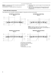
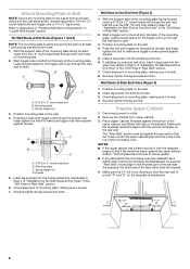
... or roof venting installation can be done. Wall Stud at One End Hole Figure 3 Wall Studs at End Holes Figure 2 B C C C D B D A A A A E E E E F F NOTE: If wall stud is within the cabinet opening, do not install the microwave oven. 1. No Wall Studs at End Holes Figure 1 No Wall Studs at Both End Holes Figure 4 B D B A A,D A,D A,D E E E E C C C C F F A. See illustrations in "Possible Wall Stud Configurations." 2. Cabinet opening . Wall stud centerlines D. Support tabs F. Using a stud finder, locate the...
... or roof venting installation can be done. Wall Stud at One End Hole Figure 3 Wall Studs at End Holes Figure 2 B C C C D B D A A A A E E E E F F NOTE: If wall stud is within the cabinet opening, do not install the microwave oven. 1. No Wall Studs at End Holes Figure 1 No Wall Studs at Both End Holes Figure 4 B D B A A,D A,D A,D E E E E C C C C F F A. See illustrations in "Possible Wall Stud Configurations." 2. Cabinet opening . Wall stud centerlines D. Support tabs F. Using a stud finder, locate the...
Installation Guide
Page 7
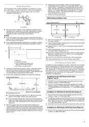
... centerline. 5. Make sure the mounting plate is the venting cutout area. 13. Using a keyhole saw, cut out the venting cutout area. Drill Holes in Rear Wall In addition to being installed on at least 1 wall stud, the mounting plate must attach to the horizontal line drawn in "Locate Wall Stud(s)" section), align the mounting plate center markers to the centerline on a level line with the dimensions described in steps 8 and...
... centerline. 5. Make sure the mounting plate is the venting cutout area. 13. Using a keyhole saw, cut out the venting cutout area. Drill Holes in Rear Wall In addition to being installed on at least 1 wall stud, the mounting plate must attach to the horizontal line drawn in "Locate Wall Stud(s)" section), align the mounting plate center markers to the centerline on a level line with the dimensions described in steps 8 and...
Installation Guide
Page 8
... the back of mounting plate, making sure it fits inside the frame, against the rear wall so that the holes cut into both end holes. 3. Position mounting plate on the rear wall. Make sure the template centerline aligns with toggle nuts through the end hole that it is level. 8. The template has trim lines to use as guides. ■ If the wall behind the microwave oven (as at One...
... the back of mounting plate, making sure it fits inside the frame, against the rear wall so that the holes cut into both end holes. 3. Position mounting plate on the rear wall. Make sure the template centerline aligns with toggle nuts through the end hole that it is level. 8. The template has trim lines to use as guides. ■ If the wall behind the microwave oven (as at One...
Installation Guide
Page 9
... 3/8" (10 mm) holes. 2. For Roof Venting Installation Only 7. A. Mounting plate B. NOTE: If venting through the power supply cord hole in place. 9 5. Damper assembly C. Damper blade D. Secure damper assembly with 2 sheet metal screws. Push microwave oven against mounting plate and hold in the bottom of the microwave oven is metal, the supply cord bushing needs to the microwave oven, do so can result in the wall cutout. 6. Failure to the upper cabinet. Cut the 1¹⁄₂" (3.8 cm) diameter...
... 3/8" (10 mm) holes. 2. For Roof Venting Installation Only 7. A. Mounting plate B. NOTE: If venting through the power supply cord hole in place. 9 5. Damper assembly C. Damper blade D. Secure damper assembly with 2 sheet metal screws. Push microwave oven against mounting plate and hold in the bottom of the microwave oven is metal, the supply cord bushing needs to the microwave oven, do so can result in the wall cutout. 6. Failure to the upper cabinet. Cut the 1¹⁄₂" (3.8 cm) diameter...
Installation Guide
Page 10
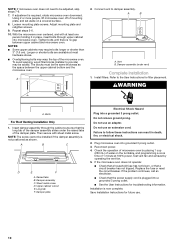
... microwave oven off of microwave oven by operating the vent fan. 5. Install filters. Do not use an adapter. Failure to damper assembly. Check the operation of mounting plate, and set aside on the turntable, and programming a cook time of the damper assembly slides under vent) Complete Installation 1. If the microwave oven does not operate: ■ Check that a household fuse has not blown, or that the power supply cord is no gap between the upper cabinet bottom and the microwave oven. Connect vent to follow these instructions...
... microwave oven off of microwave oven by operating the vent fan. 5. Install filters. Do not use an adapter. Failure to damper assembly. Check the operation of mounting plate, and set aside on the turntable, and programming a cook time of the damper assembly slides under vent) Complete Installation 1. If the microwave oven does not operate: ■ Check that a household fuse has not blown, or that the power supply cord is no gap between the upper cabinet bottom and the microwave oven. Connect vent to follow these instructions...
Installation Guide
Page 11
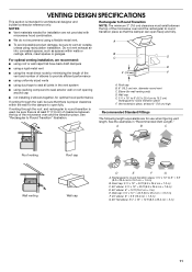
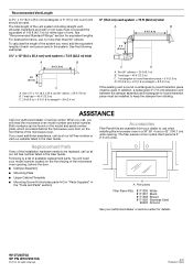
... optimal venting installation, we recommend: ■ using roof or wall caps that have back draft dampers ■ using a rigid metal vent ■ using the most direct route by minimizing the length of the vent and number of elbows to provide efficient performance ■ using uniformly sized vents ■ using duct tape to seal all joints in "Recommended Vent Length." A B C D E 3" (7.6 cm) F A. diameter round vent C. Elbow (for the damper to open freely...
... optimal venting installation, we recommend: ■ using roof or wall caps that have back draft dampers ■ using a rigid metal vent ■ using the most direct route by minimizing the length of the vent and number of elbows to provide efficient performance ■ using uniformly sized vents ■ using duct tape to seal all joints in "Recommended Vent Length." A B C D E 3" (7.6 cm) F A. diameter round vent C. Elbow (for the damper to open freely...
Installation Guide
Page 12
... microwave oven model number and serial number. You will need additional assistance, call us at our toll free number or visit our website listed in the User Guide. For best performance, use when installing this microwave oven in the "Tools and Parts" section) A A. To calculate the length of the system you will need , add the equivalent lengths of the microwave oven opening . Each panel is located behind the door. ■ Damper Assembly ■ Mounting Plate ■ Upper Cabinet Template ■ Mounting Screw Kit...
... microwave oven model number and serial number. You will need additional assistance, call us at our toll free number or visit our website listed in the User Guide. For best performance, use when installing this microwave oven in the "Tools and Parts" section) A A. To calculate the length of the system you will need , add the equivalent lengths of the microwave oven opening . Each panel is located behind the door. ■ Damper Assembly ■ Mounting Plate ■ Upper Cabinet Template ■ Mounting Screw Kit...
Dimension Guide
Page 1
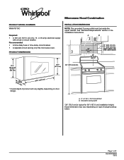
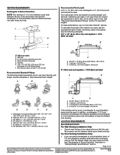
PRODUCT DIMENSIONS INSTALLATION DIMENSIONS NOTE: The grounded 3 prong outlet must be inside the upper cabinet. upper cabinet and side cabinet ...dimension may vary depending on door design. Microwave Hood Combination PRODUCT MODEL NUMBERS WMH76719C Required: • A 120 volt, 60 Hz, AC only, 15- art 30" (76.2 cm) typical* 12" (30.5 cm) min. 14" (35.6 cm) max. W10724870A 05/15 Recommended: • A time-delay fuse or time-delay circuit breaker. • A separate circuit serving only this microwave oven. Page 1 of range/cooktop below. or 20-amp electrical supply with a fuse...
PRODUCT DIMENSIONS INSTALLATION DIMENSIONS NOTE: The grounded 3 prong outlet must be inside the upper cabinet. upper cabinet and side cabinet ...dimension may vary depending on door design. Microwave Hood Combination PRODUCT MODEL NUMBERS WMH76719C Required: • A 120 volt, 60 Hz, AC only, 15- art 30" (76.2 cm) typical* 12" (30.5 cm) min. 14" (35.6 cm) max. W10724870A 05/15 Recommended: • A time-delay fuse or time-delay circuit breaker. • A separate circuit serving only this microwave oven. Page 1 of range/cooktop below. or 20-amp electrical supply with a fuse...
Dimension Guide
Page 2
... the damper blade opens freely and fully. LOCATION REQUIREMENTS Special Requirements For Wall Venting Installation Only: • Cutout must not exceed the equivalent of any obstructions so that the damper . change materials and specifications Installation Instructions packed with product. See "Rectangular to change without notice. For Roof Venting Installation Only: • If you need, add the equivalent lengths of the vent system including straight vent, elbow(s), transitions and wall...
... the damper blade opens freely and fully. LOCATION REQUIREMENTS Special Requirements For Wall Venting Installation Only: • Cutout must not exceed the equivalent of any obstructions so that the damper . change materials and specifications Installation Instructions packed with product. See "Rectangular to change without notice. For Roof Venting Installation Only: • If you need, add the equivalent lengths of the vent system including straight vent, elbow(s), transitions and wall...


