Installation Instructions
Page 2
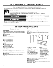
...; Charcoal filters (Depending on model, aluminum grease filter and charcoal filter may not be included. See the "Venting Design Specifications" section. 2 MICROWAVE HOOD COMBINATION SAFETY INSTALLATION REQUIREMENTS Tools and Parts Tools Needed Gather the required tools and parts before starting...
...; Charcoal filters (Depending on model, aluminum grease filter and charcoal filter may not be included. See the "Venting Design Specifications" section. 2 MICROWAVE HOOD COMBINATION SAFETY INSTALLATION REQUIREMENTS Tools and Parts Tools Needed Gather the required tools and parts before starting...
Installation Instructions
Page 3
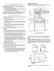
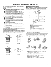
...opens freely and fully. upper cabinet and side cabinet depth A. 2" x 4" (5.1 x 10.2 cm) wall stud B. The location must be purchased from Whirlpool. 12" DEEPER 14" 14" DEEPER 15" I bar mounting plate fr om the wall. Check with your model, skip "Remove Cardboard Template" steps ...) *Overall depth of product will vary slightly depending on type of any obstructions so that the damper blade can open freely and fully. See the "Installation Dimensions" illustration. ■■ Minimum one 2" x 4" (5.1 x 10.2 cm) wood wall stud and minimum 3/8" (1 cm) thickness drywall or...
...opens freely and fully. upper cabinet and side cabinet depth A. 2" x 4" (5.1 x 10.2 cm) wall stud B. The location must be purchased from Whirlpool. 12" DEEPER 14" 14" DEEPER 15" I bar mounting plate fr om the wall. Check with your model, skip "Remove Cardboard Template" steps ...) *Overall depth of product will vary slightly depending on type of any obstructions so that the damper blade can open freely and fully. See the "Installation Dimensions" illustration. ■■ Minimum one 2" x 4" (5.1 x 10.2 cm) wood wall stud and minimum 3/8" (1 cm) thickness drywall or...
Installation Instructions
Page 4
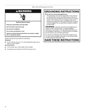
... extension cord. WARNING: Improper use an extension cord. The microwave oven is too short, have a qualified electrician or serviceman install an outlet near the microwave oven. Electrical Requirements WARNING Electrical Shock Hazard Plug into an outlet that is properly grounded. Observe all... cord connected appliances: The microwave oven must be grounded. Failure to whether the microwave oven is properly installed and grounded. Do not use of electric shock by providing an escape wire for the electric current. Required: ■■ A ...
... extension cord. WARNING: Improper use an extension cord. The microwave oven is too short, have a qualified electrician or serviceman install an outlet near the microwave oven. Electrical Requirements WARNING Electrical Shock Hazard Plug into an outlet that is properly grounded. Observe all... cord connected appliances: The microwave oven must be grounded. Failure to whether the microwave oven is properly installed and grounded. Do not use of electric shock by providing an escape wire for the electric current. Required: ■■ A ...
Installation Instructions
Page 5
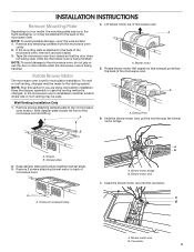
... handled. Slide damper plate toward the front of microwave oven. Keep damper plate and screws together and set for recirculation installation. Screws (in another location where wall or roof venting may be attached to the back of the microwave oven, remove... Blower motor wire 7. Blower motor wire B. Remove any remaining contents from the microwave oven cavity. 2. B A. Damper plate 2. A A. A A. Connector 5 INSTALLATION INSTRUCTIONS Remove Mounting Plate Depending on your model, the mounting plate may be in the foam packaging, or it may be used. 4. NOTE: To avoid...
... handled. Slide damper plate toward the front of microwave oven. Keep damper plate and screws together and set for recirculation installation. Screws (in another location where wall or roof venting may be attached to the back of the microwave oven, remove... Blower motor wire 7. Blower motor wire B. Remove any remaining contents from the microwave oven cavity. 2. B A. Damper plate 2. A A. A A. Connector 5 INSTALLATION INSTRUCTIONS Remove Mounting Plate Depending on your model, the mounting plate may be in the foam packaging, or it may be used. 4. NOTE: To avoid...
Installation Instructions
Page 6
... oriented, the 2 screws removed in the top of the microwave oven. Securely tighten screws. Repeat Step 2 from "Wall Venting Installation Only." 2. Secure damper plate with flat side facing the back of the microwave oven (as shown), performance will be reattached to...oven with the 2 screws removed in Step 1. Rectangular vent covers 7. Screws C. Repeat Step 1 from "Wall Venting Installation Only." 3. Repeat Step 3 from "Wall Venting Installation Only." 5. Rotate blower motor so that exhaust ports face the top of microwave oven, and flat sides of blower ...
... oriented, the 2 screws removed in the top of the microwave oven. Securely tighten screws. Repeat Step 2 from "Wall Venting Installation Only." 2. Secure damper plate with flat side facing the back of the microwave oven (as shown), performance will be reattached to...oven with the 2 screws removed in Step 1. Rectangular vent covers 7. Screws C. Repeat Step 1 from "Wall Venting Installation Only." 3. Repeat Step 3 from "Wall Venting Installation Only." 5. Rotate blower motor so that exhaust ports face the top of microwave oven, and flat sides of blower ...
Installation Instructions
Page 7
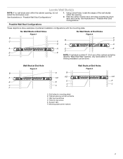
...A,D A,D E E E E C C C C F F A. End holes (on mounting plate) B. Support tabs F. Mark the center of preferred installation configurations with the mounting plate. Wall stud centerlines D. Holes for lag screws E. See illustrations in "Possible Wall Stud Configurations." 1. Cabinet opening . 2. ... E E F NOTE: If wall stud is within 6" (15.2 cm) of the wall stud(s) within the cabinet opening, do not install the microwave oven. Using a stud finder, locate the edges of the vertical centerline (see the "Mark Rear Wall" section), only recirculation or roof...
...A,D A,D E E E E C C C C F F A. End holes (on mounting plate) B. Support tabs F. Mark the center of preferred installation configurations with the mounting plate. Wall stud centerlines D. Holes for lag screws E. See illustrations in "Possible Wall Stud Configurations." 1. Cabinet opening . 2. ... E E F NOTE: If wall stud is within 6" (15.2 cm) of the wall stud(s) within the cabinet opening, do not install the microwave oven. Using a stud finder, locate the edges of the vertical centerline (see the "Mark Rear Wall" section), only recirculation or roof...
Installation Instructions
Page 8
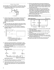
... at least 1, preferably 2 hole(s) through the marks made in Step 3 and that the end holes are ideal hole locations. 7. They must be installed on the wall, making sure it is level, and that its bottom edge is aligned to the centerline on a minimum of 1 wall stud, preferably... of the cabinet. ■■ If the cardboard template or wall template is butted up against the bottom edge of the upper cabinet. Wall Venting Installation Only Upper cabinet bottom ³⁄₈" (1 cm) 4" (10.2 cm) Centerline 6" (15.2 cm) 6" (15.2 cm) 8. Using measuring tape, find and...
... at least 1, preferably 2 hole(s) through the marks made in Step 3 and that the end holes are ideal hole locations. 7. They must be installed on the wall, making sure it is level, and that its bottom edge is aligned to the centerline on a minimum of 1 wall stud, preferably... of the cabinet. ■■ If the cardboard template or wall template is butted up against the bottom edge of the upper cabinet. Wall Venting Installation Only Upper cabinet bottom ³⁄₈" (1 cm) 4" (10.2 cm) Centerline 6" (15.2 cm) 6" (15.2 cm) 8. Using measuring tape, find and...
Installation Instructions
Page 9
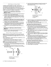
... the wall studs and/or drywall using either 3/16-24 x 3" (7.6 cm) round-head bolts and toggle nuts or 1/4 x 2" (5.1 cm) lag screws. Installation for the toggle nuts to go through the drywall, and finger tighten the bolts to make sure toggle nut has opened against drywall. 5. Drill Holes.... 7. Securely tighten the lag screws. Mounting plate C. Securely tighten the lag screw(s) and bolt. Insert lag screws into the remaining end hole. 6. Installation for the toggle nut to the wall at One End Hole (Figure 3) 1. Drill a 3/16" (5 mm) hole into the wall stud(s) at...
... the wall studs and/or drywall using either 3/16-24 x 3" (7.6 cm) round-head bolts and toggle nuts or 1/4 x 2" (5.1 cm) lag screws. Installation for the toggle nuts to go through the drywall, and finger tighten the bolts to make sure toggle nut has opened against drywall. 5. Drill Holes.... 7. Securely tighten the lag screws. Mounting plate C. Securely tighten the lag screw(s) and bolt. Insert lag screws into the remaining end hole. 6. Installation for the toggle nut to the wall at One End Hole (Figure 3) 1. Drill a 3/16" (5 mm) hole into the wall stud(s) at...
Installation Instructions
Page 10
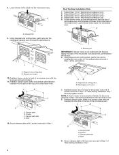
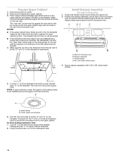
... x 3/8" Sheet metal screws 3. NOTE: If upper cabinet is at points "D" and "E" on the template. Back of the microwave oven. For Roof Venting Installation Only: 7. Cut 3/4" (1.9 cm) hole at the circular shaded area "G" on the template. Position the damper assembly on the back of the shaded rectangular area... upper cabinet, and attach with the holes in the top of microwave oven B. This hole is maintained. Disconnect power to be installed around it, trim the template edges so that damper blade moves freely and opens fully. 2. Place Upper Cabinet Template against the ...
... x 3/8" Sheet metal screws 3. NOTE: If upper cabinet is at points "D" and "E" on the template. Back of the microwave oven. For Roof Venting Installation Only: 7. Cut 3/4" (1.9 cm) hole at the circular shaded area "G" on the template. Position the damper assembly on the back of the shaded rectangular area... upper cabinet, and attach with the holes in the top of microwave oven B. This hole is maintained. Disconnect power to be installed around it, trim the template edges so that damper blade moves freely and opens fully. 2. Place Upper Cabinet Template against the ...
Installation Instructions
Page 11
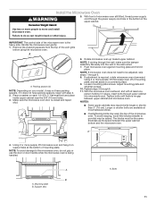
... Adjust mounting plate and retighten screws. 10. With the microwave oven centered, and with step 2. 2. To avoid warping, wood filler blocks (installer to move and install microwave oven. A 4. Push microwave oven against mounting plate and hold in the wall cutout. 7. Using 2 or more people to provide) ...downward. NOTE: To avoid damage to do not grip or use the door or door handle while the microwave oven is the heavy side. Install the Microwave Oven WARNING 5. Place a washer on your model, it in the bottom of microwave oven still tilted, thread power supply cord...
... Adjust mounting plate and retighten screws. 10. With the microwave oven centered, and with step 2. 2. To avoid warping, wood filler blocks (installer to move and install microwave oven. A 4. Push microwave oven against mounting plate and hold in the wall cutout. 7. Using 2 or more people to provide) ...downward. NOTE: To avoid damage to do not grip or use the door or door handle while the microwave oven is the heavy side. Install the Microwave Oven WARNING 5. Place a washer on your model, it in the bottom of microwave oven still tilted, thread power supply cord...
Installation Instructions
Page 12
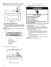
...to the User Instructions for troubleshooting information. Bolt B. Long tab F. Do not remove ground prong. Save Installation Instructions for future use an extension cord. Install filters. Check the operation of microwave oven by placing 1 cup (250 mL) of water on the turntable... so that a circuit breaker has not tripped. Raised tabs B. The installation is not positioned as shown. Mounting Nut For Roof Venting Installation Only 1. Then secure with tools. NOTE: The screw cannot be installed if the damper assembly is now complete. Reconnect power. 4. A 15...
...to the User Instructions for troubleshooting information. Bolt B. Long tab F. Do not remove ground prong. Save Installation Instructions for future use an extension cord. Install filters. Check the operation of microwave oven by placing 1 cup (250 mL) of water on the turntable... so that a circuit breaker has not tripped. Raised tabs B. The installation is not positioned as shown. Mounting Nut For Roof Venting Installation Only 1. Then secure with tools. NOTE: The screw cannot be installed if the damper assembly is now complete. Reconnect power. 4. A 15...
Installation Instructions
Page 13
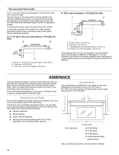
... least 3" (7.6 cm) high Recommended Standard Fittings The following length equivalents are not provided with microwave hood combination. ■■ We do not recommend using recirculation installation. A B C D E 3" (7.6 cm) F A. Wall cap E. 31⁄4" x 10" to 6" (8.3 x 25.4 cm to 15.2 cm) rectangular-to ...10" to 6" = 5 ft (8.3 x 25.4 cm to -round transition piece F. NOTES: ■■ Vent materials needed for installation are for architectural designer and builder/ contractor reference only. If venting through the wall, be sure to -round transition piece so that have ...
... least 3" (7.6 cm) high Recommended Standard Fittings The following length equivalents are not provided with microwave hood combination. ■■ We do not recommend using recirculation installation. A B C D E 3" (7.6 cm) F A. Wall cap E. 31⁄4" x 10" to 6" (8.3 x 25.4 cm to 15.2 cm) rectangular-to ...10" to 6" = 5 ft (8.3 x 25.4 cm to -round transition piece F. NOTES: ■■ Vent materials needed for installation are for architectural designer and builder/ contractor reference only. If venting through the wall, be sure to -round transition piece so that have ...
Installation Instructions
Page 14
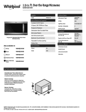
...to keep the damper from your model and serial numbers located on the front frame of the microwave oven opening . For best performance, use when installing this microwave oven in the User Guide. In addition, a rectangular 3" (7.6 cm) extension vent between the damper assembly and rectangular to round ... If any of vent. Accessories Filler Panel Kits are available from sticking. See the "Recommended Standard Fittings" section for either type of the installation hardware needs to use no more than three 90° elbows. When you call, you need your dealer to be replaced, call us ...
...to keep the damper from your model and serial numbers located on the front frame of the microwave oven opening . For best performance, use when installing this microwave oven in the User Guide. In addition, a rectangular 3" (7.6 cm) extension vent between the damper assembly and rectangular to round ... If any of vent. Accessories Filler Panel Kits are available from sticking. See the "Recommended Standard Fittings" section for either type of the installation hardware needs to use no more than three 90° elbows. When you call, you need your dealer to be replaced, call us ...
Specification Sheet
Page 1
... Speeds Venting Type Dimensions Product Dimensions (H x W x D) Depth with Door Open 90° Cutout Dimensions (W x D) Reference Material Dimension Guide Install Guide Use & Care Guide Warranty Over-theRange 300 Incandescent 3 Updraft 17-1/8" x 29-15/16" x 15-9/16" 39-3/8" 30" x 12"...reserved. WMH32519HSpecSheetV01. ft. NOTE: Dimensions are for planning purposes only. Over-the-Range Microwave WMH32519H Fingerprint Resistant Stainless Steel WMH32519HZ Also available in the U.S.A. General Features & Properties Turntable On/Off Option 3-Speed, 300 CFM Motor Class Fingerprint Resistant...
... Speeds Venting Type Dimensions Product Dimensions (H x W x D) Depth with Door Open 90° Cutout Dimensions (W x D) Reference Material Dimension Guide Install Guide Use & Care Guide Warranty Over-theRange 300 Incandescent 3 Updraft 17-1/8" x 29-15/16" x 15-9/16" 39-3/8" 30" x 12"...reserved. WMH32519HSpecSheetV01. ft. NOTE: Dimensions are for planning purposes only. Over-the-Range Microwave WMH32519H Fingerprint Resistant Stainless Steel WMH32519HZ Also available in the U.S.A. General Features & Properties Turntable On/Off Option 3-Speed, 300 CFM Motor Class Fingerprint Resistant...


