Dimension Guide
Page 1
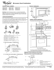
... for wall venting only) E D. To calculate the length of vent. A 2 ft (0.6 m) C A. Instructions packed with a fuse or circuit breaker. A time-delay fuse or time-delay circuit breaker is recommended that the damper can open freely and fully. Rectangular to round transition piece: 3 " x 10" to 6" = 5 ft (8.3 x 25.4 cm to improve Dimensions are for 66" (167.6 cm) installation height. Vent extension piece, at least 3" (7.6 cm) high Because Whirlpool Corporation...
... for wall venting only) E D. To calculate the length of vent. A 2 ft (0.6 m) C A. Instructions packed with a fuse or circuit breaker. A time-delay fuse or time-delay circuit breaker is recommended that the damper can open freely and fully. Rectangular to round transition piece: 3 " x 10" to 6" = 5 ft (8.3 x 25.4 cm to improve Dimensions are for 66" (167.6 cm) installation height. Vent extension piece, at least 3" (7.6 cm) high Because Whirlpool Corporation...

Installation Instructions
Page 1
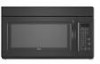
... Requirements" section for use above electric or gas cooking products up to reduce the chance of Contents MICROWAVE HOOD COMBINATION SAFETY 1 INSTALLATION REQUIREMENTS 2 Tools and Parts 2 Remove Cardboard Template 2 Location Requirements 2 Product Dimensions 3 Electrical Requirements 3 INSTALLATION INSTRUCTIONS 4 Remove Mounting Plate 4 Rotate Blower Motor 4 Locate Wall Stud(s 6 Mark Rear Wall 7 Drill Holes in these installation instructions. This symbol alerts you don't follow instructions. The appearance of others . All safety messages will tell you what...
... Requirements" section for use above electric or gas cooking products up to reduce the chance of Contents MICROWAVE HOOD COMBINATION SAFETY 1 INSTALLATION REQUIREMENTS 2 Tools and Parts 2 Remove Cardboard Template 2 Location Requirements 2 Product Dimensions 3 Electrical Requirements 3 INSTALLATION INSTRUCTIONS 4 Remove Mounting Plate 4 Rotate Blower Motor 4 Locate Wall Stud(s 6 Mark Rear Wall 7 Drill Holes in these installation instructions. This symbol alerts you don't follow instructions. The appearance of others . All safety messages will tell you what...

Installation Instructions
Page 2
...grease filters Charcoal filters (Depending on model, aluminum grease filter and charcoal filter may not be sure to back of microwave oven) Cardboard template (part of wall structures, be included. Special Requirements For Wall Venting Installation Only: ■ Cutout must provide: ■ Minimum installation dimensions. hole drill ■ No. 2 Phillips screwdriver bit for wood or metal ■ No. 3 Phillips screwdriver for wall or roof venting) Not Shown: Upper cabinet template Mounting plate (attached to use as a rear wall template. 1. Washers (2) D. Damper assembly...
...grease filters Charcoal filters (Depending on model, aluminum grease filter and charcoal filter may not be sure to back of microwave oven) Cardboard template (part of wall structures, be included. Special Requirements For Wall Venting Installation Only: ■ Cutout must provide: ■ Minimum installation dimensions. hole drill ■ No. 2 Phillips screwdriver bit for wood or metal ■ No. 3 Phillips screwdriver for wall or roof venting) Not Shown: Upper cabinet template Mounting plate (attached to use as a rear wall template. 1. Washers (2) D. Damper assembly...

Installation Instructions
Page 3
... INSTRUCTIONS ■ For all governing codes and ordinances. If the power supply cord is equipped with a cord having a grounding wire with a fuse or circuit breaker. See "Electrical Requirements" section. Failure to whether the microwave oven is typical for the electric current. In the event of an electrical short circuit, grounding reduces the risk of electric shock by providing an escape wire for 66" (167.6 cm) installation height...
... INSTRUCTIONS ■ For all governing codes and ordinances. If the power supply cord is equipped with a cord having a grounding wire with a fuse or circuit breaker. See "Electrical Requirements" section. Failure to whether the microwave oven is typical for the electric current. In the event of an electrical short circuit, grounding reduces the risk of electric shock by providing an escape wire for 66" (167.6 cm) installation height...

Installation Instructions
Page 4
... the microwave oven. Blower motor 5. INSTALLATION INSTRUCTIONS Remove Mounting Plate Depending on your model, the mounting plate may be in Step 1. 4 Make sure damper plate tabs are using recirculation installation. If the mounting plate is being handled. NOTE: Skip this section if you are inserted into the microwave oven. Reattach blower motor to back of microwave oven with 2 screws removed in the foam packaging, or it may be attached to the venting system. Screws (in another location where wall...
... the microwave oven. Blower motor 5. INSTALLATION INSTRUCTIONS Remove Mounting Plate Depending on your model, the mounting plate may be in Step 1. 4 Make sure damper plate tabs are using recirculation installation. If the mounting plate is being handled. NOTE: Skip this section if you are inserted into the microwave oven. Reattach blower motor to back of microwave oven with 2 screws removed in the foam packaging, or it may be attached to the venting system. Screws (in another location where wall...

Installation Instructions
Page 5
... of microwave oven with 2 screws removed in Step 1 of the microwave oven. Repeat Step 4 from "Wall Venting Installation Only." 2. A 6. A B C A. Exhaust port IMPORTANT: If blower motor is not correctly oriented, the 2 screws removed in the top of "Wall Venting Installation Only." 5 Roof Venting Installation Only 1. Repeat Step 1 from "Wall Venting Installation Only." 5. Make sure damper plate tabs are inserted into microwave oven. Slots 8. Repeat Step 2 from "Wall Venting Installation Only." 4. Reattach blower motor to the microwave oven. 7. Reattach damper plate. Lower...
... of microwave oven with 2 screws removed in Step 1 of the microwave oven. Repeat Step 4 from "Wall Venting Installation Only." 2. A 6. A B C A. Exhaust port IMPORTANT: If blower motor is not correctly oriented, the 2 screws removed in the top of "Wall Venting Installation Only." 5 Roof Venting Installation Only 1. Repeat Step 1 from "Wall Venting Installation Only." 5. Make sure damper plate tabs are inserted into microwave oven. Slots 8. Repeat Step 2 from "Wall Venting Installation Only." 4. Reattach blower motor to the microwave oven. 7. Reattach damper plate. Lower...

Installation Instructions
Page 6
... mounting plate. End holes (on mounting plate) B. Support tabs F. See illustrations in "Possible Wall Stud Configurations." 2. Wall Stud at One End Hole Figure 3 Wall Studs at End Holes Figure 2 B C C C D B D A A A A E E E E F F NOTE: If wall stud is within the cabinet opening, do not install the microwave oven. 1. Locate Wall Stud(s) NOTE: If no wall studs exist within 6" (15.2 cm) of the vertical centerline (see "Mark Rear Wall" section), only recirculation or roof venting installation...
... mounting plate. End holes (on mounting plate) B. Support tabs F. See illustrations in "Possible Wall Stud Configurations." 2. Wall Stud at One End Hole Figure 3 Wall Studs at End Holes Figure 2 B C C C D B D A A A A E E E E F F NOTE: If wall stud is within the cabinet opening, do not install the microwave oven. 1. Locate Wall Stud(s) NOTE: If no wall studs exist within 6" (15.2 cm) of the vertical centerline (see "Mark Rear Wall" section), only recirculation or roof venting installation...

Installation Instructions
Page 7
... mounting plate is the venting cutout area. 13. Set the mounting plate aside. Draw the 2 vertical, plumb lines down from the mark made in one 1/4-20 x 3" round-head bolt with front edge of cabinet. Using a keyhole saw, cut out the venting cutout area. A A. D A C B A. Top of cardboard template must align with toggle nut; Front edge of upper cabinet 3. With the support tabs facing forward (see illustrations in "Locate Wall...
... mounting plate is the venting cutout area. 13. Set the mounting plate aside. Draw the 2 vertical, plumb lines down from the mark made in one 1/4-20 x 3" round-head bolt with front edge of cabinet. Using a keyhole saw, cut out the venting cutout area. A A. D A C B A. Top of cardboard template must align with toggle nut; Front edge of upper cabinet 3. With the support tabs facing forward (see illustrations in "Locate Wall...

Installation Instructions
Page 8
... mounting plate, making sure it fits inside the frame, against the bottom of "Mark Rear Wall." Remove all lag screws and bolts. The "rear wall" arrows must be secured to open . B D A. 1/4-20 x 3" round-head bolt B. Wall Stud at Both End Holes (Figure 4) 1. Position mounting plate on the wall. 2. Securely tighten the lag screw(s) and bolt. NOTES: ■ If the upper cabinet has a frame around it, trim the template...
... mounting plate, making sure it fits inside the frame, against the bottom of "Mark Rear Wall." Remove all lag screws and bolts. The "rear wall" arrows must be secured to open . B D A. 1/4-20 x 3" round-head bolt B. Wall Stud at Both End Holes (Figure 4) 1. Position mounting plate on the wall. 2. Securely tighten the lag screw(s) and bolt. NOTES: ■ If the upper cabinet has a frame around it, trim the template...

Installation Instructions
Page 9
... handled. Sheet metal screws 3. Check that the damper blade hinge is closed and taped shut. 3. Place a washer on the template. 5. Mounting plate B. Position the damper assembly on the template. Cut the 1¹⁄₂" (3.8 cm) diameter hole at one corner of mounting plate. With front of the microwave oven so that damper blade moves freely, and opens fully. 2. Back of the upper cabinet. 5. NOTE: If venting through the power supply cord...
... handled. Sheet metal screws 3. Check that the damper blade hinge is closed and taped shut. 3. Place a washer on the template. 5. Mounting plate B. Position the damper assembly on the template. Cut the 1¹⁄₂" (3.8 cm) diameter hole at one corner of mounting plate. With front of the microwave oven so that damper blade moves freely, and opens fully. 2. Back of the upper cabinet. 5. NOTE: If venting through the power supply cord...

Installation Instructions
Page 10
... the damper plate. Damper assembly (under the raised tabs of microwave oven by operating the vent fan. 5. Do not remove ground prong. Install filters. With the microwave oven centered, and with sheet metal screw. Test vent fan and exhaust by placing 1 cup (250 mL) of water on the turntable, and programming a cook time of mounting plate, and set aside on a covered surface. 8. Replace the fuse or reset the circuit breaker. Adjust mounting plate and retighten screws. 9. Upper cabinet cutout E. Do not use an adapter. Long tab F. A 2. Reconnect power...
... the damper plate. Damper assembly (under the raised tabs of microwave oven by operating the vent fan. 5. Do not remove ground prong. Install filters. With the microwave oven centered, and with sheet metal screw. Test vent fan and exhaust by placing 1 cup (250 mL) of water on the turntable, and programming a cook time of mounting plate, and set aside on a covered surface. 8. Replace the fuse or reset the circuit breaker. Adjust mounting plate and retighten screws. 9. Upper cabinet cutout E. Do not use an adapter. Long tab F. A 2. Reconnect power...

Installation Instructions
Page 11
... = 1.5 m) B. Do not vent exhaust air into concealed spaces, such as spaces within the wall for wall venting only) D. For optimal venting installation, we recommend: ■ using roof or wall caps that have back draft dampers ■ using a rigid metal vent ■ using the most direct route by minimizing the length of the vent and number of elbows to provide efficient performance ■ using uniformly sized vents ■ using duct tape to...
... = 1.5 m) B. Do not vent exhaust air into concealed spaces, such as spaces within the wall for wall venting only) D. For optimal venting installation, we recommend: ■ using roof or wall caps that have back draft dampers ■ using a rigid metal vent ■ using the most direct route by minimizing the length of the vent and number of elbows to provide efficient performance ■ using uniformly sized vents ■ using duct tape to...

Installation Instructions
Page 12
.... Following is located behind the door. ■ Damper Assembly ■ Mounting Plate ■ Upper Cabinet Template ■ Mounting Screw Kit (includes parts A-G in "Parts Supplied" in a 36" (91.4 cm) or 42" (106.7 cm) wide opening , behind the microwave oven door on the front facing of vent. Recommended Vent Length A 3¹⁄₄" x 10" (8.3 x 25.4 cm) rectangular or 6" (15.2 cm) round vent should be replaced, call us at our toll free number listed in the...
.... Following is located behind the door. ■ Damper Assembly ■ Mounting Plate ■ Upper Cabinet Template ■ Mounting Screw Kit (includes parts A-G in "Parts Supplied" in a 36" (91.4 cm) or 42" (106.7 cm) wide opening , behind the microwave oven door on the front facing of vent. Recommended Vent Length A 3¹⁄₄" x 10" (8.3 x 25.4 cm) rectangular or 6" (15.2 cm) round vent should be replaced, call us at our toll free number listed in the...
Owners Manual
Page 1
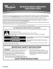
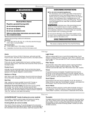
... the instructions are not followed. are very important. If you what can be followed, including the following: WARNING: To reduce the risk of the microwave oven opening, behind the door. This symbol alerts you to excessive microwave energy: ■ Install or locate the microwave oven only in this high-quality product. All safety messages will tell you still need your model and serial number located...
... the instructions are not followed. are very important. If you what can be followed, including the following: WARNING: To reduce the risk of the microwave oven opening, behind the door. This symbol alerts you to excessive microwave energy: ■ Install or locate the microwave oven only in this high-quality product. All safety messages will tell you still need your model and serial number located...
Owners Manual
Page 2
... in operation. ■ When flambeing foods under the hood, turn oven off, and disconnect the power cord, or shut off the pad and touch electrical parts involving a risk of 36" (91.44 cm). ■ Clean Ventilating Hoods Frequently - It is particularly important that there is in the oven cavity: - Remove wire twist-ties from the microwave oven is specifically designed to heat, cook, or dry food. IMPORTANT SAFETY INSTRUCTIONS ■ Use the microwave oven only...
... in operation. ■ When flambeing foods under the hood, turn oven off, and disconnect the power cord, or shut off the pad and touch electrical parts involving a risk of 36" (91.44 cm). ■ Clean Ventilating Hoods Frequently - It is particularly important that there is in the oven cavity: - Remove wire twist-ties from the microwave oven is specifically designed to heat, cook, or dry food. IMPORTANT SAFETY INSTRUCTIONS ■ Use the microwave oven only...
Owners Manual
Page 3
... 30 minutes). Programming tones may be changed. Settings Clock The Clock is properly grounded. Light Timer Set the cooktop light to the microwave oven, always remove rack after replacing and/or cleaning the filters. Tones Programming tones and signals. Touch the Options or Setup control to set the Light On Time and Light Off Time in the display. This is properly installed and grounded. Scroll Speed Scroll speed of electric shock by side. Vent Timer (on and off . Touch the Start control to reach...
... 30 minutes). Programming tones may be changed. Settings Clock The Clock is properly grounded. Light Timer Set the cooktop light to the microwave oven, always remove rack after replacing and/or cleaning the filters. Tones Programming tones and signals. Touch the Options or Setup control to set the Light On Time and Light Off Time in the display. This is properly installed and grounded. Scroll Speed Scroll speed of electric shock by side. Vent Timer (on and off . Touch the Start control to reach...
Owners Manual
Page 4
... microwave oven opening, behind the door. Touch COOK, select food item, enter quantity if needed , then touch the Start control. Microwave Oven Use Manual Cooking/Stage Cooking Doneness (on some models) Touch COOK TIME, touch number pads to enter time, touch COOK POWER (if not 100%), touch number pads to the microwave oven cavity, do not use stainless steel cleaner. ■ Turntable: mild soap and water or dishwasher. ■ Cooking rack and supports (on the front facing of water beside it heats, and adjusts the cooking time accordingly. Preset Defrosting...
... microwave oven opening, behind the door. Touch COOK, select food item, enter quantity if needed , then touch the Start control. Microwave Oven Use Manual Cooking/Stage Cooking Doneness (on some models) Touch COOK TIME, touch number pads to enter time, touch COOK POWER (if not 100%), touch number pads to the microwave oven cavity, do not use stainless steel cleaner. ■ Turntable: mild soap and water or dishwasher. ■ Cooking rack and supports (on the front facing of water beside it heats, and adjusts the cooking time accordingly. Preset Defrosting...
Owners Manual
Page 5
... on cavity walls, microwave inlet cover, cooking rack supports, and area where the door touches the frame can cause arcing. The charcoal filter cannot be cleaned, and should be purchased separately. Troubleshooting First try the steps below is located behind the vent grille at the beginning of the door, remove it is time to cool the microwave oven's controls while the cooktop below . If the problem continues, call an electrician. ■ Magnetron Try to...
... on cavity walls, microwave inlet cover, cooking rack supports, and area where the door touches the frame can cause arcing. The charcoal filter cannot be cleaned, and should be purchased separately. Troubleshooting First try the steps below is located behind the vent grille at the beginning of the door, remove it is time to cool the microwave oven's controls while the cooktop below . If the problem continues, call an electrician. ■ Magnetron Try to...
Owners Manual
Page 6
... published installation instructions. 11. Repairs when your major appliance, to replace or repair house fuses, or to use your major appliance is not installed in -home service is covered by an authorized Whirlpool servicer is reported to published user or operator instructions and/or installation instructions. 4. Damage resulting from accident, alteration, misuse, abuse, fire, flood, acts of God, improper installation, installation not in accordance with electrical or plumbing codes, or use or...
... published installation instructions. 11. Repairs when your major appliance, to replace or repair house fuses, or to use your major appliance is not installed in -home service is covered by an authorized Whirlpool servicer is reported to published user or operator instructions and/or installation instructions. 4. Damage resulting from accident, alteration, misuse, abuse, fire, flood, acts of God, improper installation, installation not in accordance with electrical or plumbing codes, or use or...

Warranty
Page 1
... of consumables or cleaning products not approved by a Whirlpool designated service company. Proof of original purchase date is not installed in materials or workmanship. Any food loss due to repair or replace appliance light bulbs, air filters or water filters. DISCLAIMER OF IMPLIED WARRANTIES; Outside the 50 United States and Canada, this User Instructions and model number information for future reference. WHIRLPOOL CORPORATION MAJOR APPLIANCE WARRANTY LIMITED WARRANTY For one...
... of consumables or cleaning products not approved by a Whirlpool designated service company. Proof of original purchase date is not installed in materials or workmanship. Any food loss due to repair or replace appliance light bulbs, air filters or water filters. DISCLAIMER OF IMPLIED WARRANTIES; Outside the 50 United States and Canada, this User Instructions and model number information for future reference. WHIRLPOOL CORPORATION MAJOR APPLIANCE WARRANTY LIMITED WARRANTY For one...


