Dimension Guide
Page 1
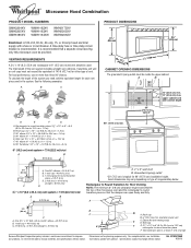
... must exist between the top of range/cooktop below. A 2 ft (0.6 m) C A. Roof cap B. 6" (15.2 cm) min. Vent extension piece, at least 3" (7.6 cm) high Because Whirlpool Corporation policy includes a continuous commitment to round transition piece = 5 ft (1.5 m) D. 2 ft (0.6 m) + 6 ft (1.8 m) straight = 8 ft (2.4 m) D 3 " x 10" ...2 ft (0.6 m) C A. Grounded 3-prong outlet *30" (76.2 cm) is recommended. For complete details, see Installation our products, we reserve the right to change materials and specifications without notice. or 20-amp fused electrical supply with product....
... must exist between the top of range/cooktop below. A 2 ft (0.6 m) C A. Roof cap B. 6" (15.2 cm) min. Vent extension piece, at least 3" (7.6 cm) high Because Whirlpool Corporation policy includes a continuous commitment to round transition piece = 5 ft (1.5 m) D. 2 ft (0.6 m) + 6 ft (1.8 m) straight = 8 ft (2.4 m) D 3 " x 10" ...2 ft (0.6 m) C A. Grounded 3-prong outlet *30" (76.2 cm) is recommended. For complete details, see Installation our products, we reserve the right to change materials and specifications without notice. or 20-amp fused electrical supply with product....

Installation Instructions
Page 1
...and either the word "DANGER" or "WARNING." See "Installation Requirements" section for use above electric or gas cooking products up to Wall 8 Prepare Upper Cabinet 8 Install Damper Assembly 9 Install the Microwave Oven 9 Complete Installation 10 VENTING DESIGN SPECIFICATIONS 11 ASSISTANCE 12 Replacement Parts 12...seriously injured if you don't follow instructions. Always read and obey all safety messages. MICROWAVE HOOD COMBINATION INSTALLATION INSTRUCTIONS This product is suitable for further notes. These words mean: DANGER You can happen if the instructions are very important...
...and either the word "DANGER" or "WARNING." See "Installation Requirements" section for use above electric or gas cooking products up to Wall 8 Prepare Upper Cabinet 8 Install Damper Assembly 9 Install the Microwave Oven 9 Complete Installation 10 VENTING DESIGN SPECIFICATIONS 11 ASSISTANCE 12 Replacement Parts 12...seriously injured if you don't follow instructions. Always read and obey all safety messages. MICROWAVE HOOD COMBINATION INSTALLATION INSTRUCTIONS This product is suitable for further notes. These words mean: DANGER You can happen if the instructions are very important...

Installation Instructions
Page 2
...for weight of wall structures, be sure to it during the "Mark Rear Wall" part of the cardboard packaging. 2. The location must be included. See "Installation Dimensions" illustration. ■ Minimum one 2" x 4" (50.8 x 101.6 mm) wood wall stud and minimum 3/8" (10 mm) thickness drywall or ... the wall and the microwave oven, so that the materials used will be combined. Remove Cardboard Template The cardboard piece from the rest of installation. hole drill ■ No. 2 Phillips screwdriver bit for wood or metal ■ No. 3 Phillips screwdriver for wall or roof venting...
...for weight of wall structures, be sure to it during the "Mark Rear Wall" part of the cardboard packaging. 2. The location must be included. See "Installation Dimensions" illustration. ■ Minimum one 2" x 4" (50.8 x 101.6 mm) wood wall stud and minimum 3/8" (10 mm) thickness drywall or ... the wall and the microwave oven, so that the materials used will be combined. Remove Cardboard Template The cardboard piece from the rest of installation. hole drill ■ No. 2 Phillips screwdriver bit for wood or metal ■ No. 3 Phillips screwdriver for wall or roof venting...

Installation Instructions
Page 3
...completely understood, or if doubt exists as to follow these instructions can result in death, fire, or electrical shock. SAVE THESE INSTRUCTIONS 3 Installation Dimensions NOTE: The grounded 3 prong outlet must be plugged into a grounded 3 prong outlet. A. 2" x 4" wall stud B. Exact... dimensions may vary depending on type of electric shock by providing an escape wire for 66" (167.6 cm) installation height. Recommended: ■ A time-delay fuse or time-delay circuit breaker. ■ A separate circuit serving only this microwave oven. Do not...
...completely understood, or if doubt exists as to follow these instructions can result in death, fire, or electrical shock. SAVE THESE INSTRUCTIONS 3 Installation Dimensions NOTE: The grounded 3 prong outlet must be plugged into a grounded 3 prong outlet. A. 2" x 4" wall stud B. Exact... dimensions may vary depending on type of electric shock by providing an escape wire for 66" (167.6 cm) installation height. Recommended: ■ A time-delay fuse or time-delay circuit breaker. ■ A separate circuit serving only this microwave oven. Do not...

Installation Instructions
Page 4
...is being handled. 4. NOTE: To avoid damage to the venting system. Exhaust port 6. Make sure damper plate tabs are using recirculation installation. Damper plate 2. Slots 8. A A. Blower motor 5. Reattach blower motor to back of microwave oven. Screws (in Step 1. .... 2. Lift blower motor out of microwave oven with 2 screws removed in recessed holes) D A. A B A. Screws C. A B C A. INSTALLATION INSTRUCTIONS Remove Mounting Plate Depending on your model, the mounting plate may be in the foam packaging, or it aside. 3. Remove screws attaching damper plate...
...is being handled. 4. NOTE: To avoid damage to the venting system. Exhaust port 6. Make sure damper plate tabs are using recirculation installation. Damper plate 2. Slots 8. A A. Blower motor 5. Reattach blower motor to back of microwave oven. Screws (in Step 1. .... 2. Lift blower motor out of microwave oven with 2 screws removed in recessed holes) D A. A B A. Screws C. A B C A. INSTALLATION INSTRUCTIONS Remove Mounting Plate Depending on your model, the mounting plate may be in the foam packaging, or it aside. 3. Remove screws attaching damper plate...

Installation Instructions
Page 5
... back of microwave oven with 2 screws removed in the top of "Wall Venting Installation Only." Secure damper plate with 2 screws removed in Step 3 cannot be poor. Repeat Step 4 from "Wall Venting Installation Only." 2. Rotate blower motor so that exhaust ports face the top of microwave ...oven, and flat sides of blower motor face back of "Wall Venting Installation Only." 5 Exhaust port IMPORTANT: If blower motor is not correctly oriented, the 2 screws removed in Step 3 of the microwave oven. Damper plate...
... back of microwave oven with 2 screws removed in the top of "Wall Venting Installation Only." Secure damper plate with 2 screws removed in Step 3 cannot be poor. Repeat Step 4 from "Wall Venting Installation Only." 2. Rotate blower motor so that exhaust ports face the top of microwave ...oven, and flat sides of blower motor face back of "Wall Venting Installation Only." 5 Exhaust port IMPORTANT: If blower motor is not correctly oriented, the 2 screws removed in Step 3 of the microwave oven. Damper plate...

Installation Instructions
Page 6
... 2. Holes for lag screws E. Possible Wall Stud Configurations These depictions show examples of the wall stud(s) within the cabinet opening, do not install the microwave oven. 1. Locate Wall Stud(s) NOTE: If no wall studs exist within the opening. Mounting plate center markers 6 Using a ...stud finder, locate the edges of preferred installation configurations with the mounting plate. Mark the center of the vertical centerline (see "Mark Rear Wall" section), only recirculation or roof venting installation can be done. No Wall Studs at End Holes Figure 1 No...
... 2. Holes for lag screws E. Possible Wall Stud Configurations These depictions show examples of the wall stud(s) within the cabinet opening, do not install the microwave oven. 1. Locate Wall Stud(s) NOTE: If no wall studs exist within the opening. Mounting plate center markers 6 Using a ...stud finder, locate the edges of preferred installation configurations with the mounting plate. Mark the center of the vertical centerline (see "Mark Rear Wall" section), only recirculation or roof venting installation can be done. No Wall Studs at End Holes Figure 1 No...

Installation Instructions
Page 7
... nut; A A. Top of "Mark Rear Wall." 2. Holding the mounting plate in place, find and clearly mark the vertical centerline of "Mark Rear Wall." Wall Venting Installation Only Upper cabinet bottom ³⁄₈" (1 cm) 4" (10.2 cm) Centerline 6" (15.2 cm) 6" (15.2 cm) 8. Using a keyhole saw, cut..., measure and mark the wall with the dimensions described in Step 4. These represent the mounting plate's end holes and bottom edge. 4. Installation for No Wall Studs at least 1 wall stud, the mounting plate must align with front edge of the cabinet. ■ If the...
... nut; A A. Top of "Mark Rear Wall." 2. Holding the mounting plate in place, find and clearly mark the vertical centerline of "Mark Rear Wall." Wall Venting Installation Only Upper cabinet bottom ³⁄₈" (1 cm) 4" (10.2 cm) Centerline 6" (15.2 cm) 6" (15.2 cm) 8. Using a keyhole saw, cut..., measure and mark the wall with the dimensions described in Step 4. These represent the mounting plate's end holes and bottom edge. 4. Installation for No Wall Studs at least 1 wall stud, the mounting plate must align with front edge of the cabinet. ■ If the...

Installation Instructions
Page 8
...Refer to outlet. 2. C A 6. Position mounting plate on the wall. 4. Position mounting plate on at least 1 wall stud as well as installed) has a partial wall covering (for Wall Stud at One End Hole (Figure 3) 1. Check alignment of "Mark Rear Wall." Disconnect power to illustrations... toggle nut through the wall and to use as guides. ■ If the wall behind the microwave oven (as at One End Hole (Figure 3) 1. If installing on a second wall stud, drill a 3/16" (5 mm) hole into wall stud(s) in "Locate Wall Stud(s)" section. 3. Prepare Upper Cabinet 1. Drywall 5. B A...
...Refer to outlet. 2. C A 6. Position mounting plate on the wall. 4. Position mounting plate on at least 1 wall stud as well as installed) has a partial wall covering (for Wall Stud at One End Hole (Figure 3) 1. Check alignment of "Mark Rear Wall." Disconnect power to illustrations... toggle nut through the wall and to use as guides. ■ If the wall behind the microwave oven (as at One End Hole (Figure 3) 1. If installing on a second wall stud, drill a 3/16" (5 mm) hole into wall stud(s) in "Locate Wall Stud(s)" section. 3. Prepare Upper Cabinet 1. Drywall 5. B A...

Installation Instructions
Page 9
... and hold in the bottom of the shaded rectangular area "F" on the template. This hole is closed and taped shut. 3. For Roof Venting Installation Only 7. Handle the microwave oven gently. 1. A B A. Failure to the microwave oven, do so can result in the wall cutout. 6....of the microwave oven is at one corner of the upper cabinet. 5. Secure damper assembly with 2 sheet metal screws. B A A. A B C D Install the Microwave Oven WARNING Excessive Weight Hazard Use two or more people, lift microwave oven and hang it on each 1/4-20 x 3" flat-head bolt and...
... and hold in the bottom of the shaded rectangular area "F" on the template. This hole is closed and taped shut. 3. For Roof Venting Installation Only 7. Handle the microwave oven gently. 1. A B A. Failure to the microwave oven, do so can result in the wall cutout. 6....of the microwave oven is at one corner of the upper cabinet. 5. Secure damper assembly with 2 sheet metal screws. B A A. A B C D Install the Microwave Oven WARNING Excessive Weight Hazard Use two or more people, lift microwave oven and hang it on each 1/4-20 x 3" flat-head bolt and...

Installation Instructions
Page 10
...a cook time of the damper assembly slides under vent) Complete Installation 1. Bolts For Roof Venting Installation Only 1. Damper assembly C. Do not use an extension cord. To avoid warping, wood filler blocks (installer to provide) may be the same thickness as shown. Insert .... Tighten bolts until there is required, rotate microwave oven downward. The blocks must be added. NOTE: If microwave oven does not need to be installed if the damper assembly is plugged into microwave oven. Plug microwave oven into a grounded 3 prong outlet. A B C D E F A. Raised...
...a cook time of the damper assembly slides under vent) Complete Installation 1. Bolts For Roof Venting Installation Only 1. Damper assembly C. Do not use an extension cord. To avoid warping, wood filler blocks (installer to provide) may be the same thickness as shown. Insert .... Tighten bolts until there is required, rotate microwave oven downward. The blocks must be added. NOTE: If microwave oven does not need to be installed if the damper assembly is plugged into microwave oven. Plug microwave oven into a grounded 3 prong outlet. A B C D E F A. Raised...

Installation Instructions
Page 11
...to 6" (8.3 x 25.4 cm to 15.2 cm) rectangular to Round Transition" illustration. NOTES: ■ Vent materials needed for installation are for the damper to round transition piece so that the damper can open fully. Rectangular to Round Transition NOTE: The minimum ... vent C. See the examples in the vent system ■ using caulking compound to provide efficient performance ■ using uniformly sized vents ■ using recirculation installation. Rectangular to round transition piece: 3¹⁄₄" x 10" to 6" = 5 ft (8.3 x 25.4 cm to seal all joints in "Recommended...
...to 6" (8.3 x 25.4 cm to 15.2 cm) rectangular to Round Transition" illustration. NOTES: ■ Vent materials needed for installation are for the damper to round transition piece so that the damper can open fully. Rectangular to Round Transition NOTE: The minimum ... vent C. See the examples in the vent system ■ using caulking compound to provide efficient performance ■ using uniformly sized vents ■ using recirculation installation. Rectangular to round transition piece: 3¹⁄₄" x 10" to 6" = 5 ft (8.3 x 25.4 cm to seal all joints in "Recommended...

Installation Instructions
Page 12
... 90° elbows. In addition, a rectangular 3" (7.6 cm) extension vent between the damper assembly and rectangular to round transition piece must be installed to be used . When you call, you need additional assistance, call us at our toll free number listed in the "Tools and Parts" section... either type of the microwave oven opening . All rights reserved. 461965617428 9/10 Printed in pairs. Replacement Parts If any of the installation hardware needs to keep the damper from your model number located on the front frame of available replacement parts. Filler panels Filler Panel ...
... 90° elbows. In addition, a rectangular 3" (7.6 cm) extension vent between the damper assembly and rectangular to round transition piece must be installed to be used . When you call, you need additional assistance, call us at our toll free number listed in the "Tools and Parts" section... either type of the microwave oven opening . All rights reserved. 461965617428 9/10 Printed in pairs. Replacement Parts If any of the installation hardware needs to keep the damper from your model number located on the front frame of available replacement parts. Filler panels Filler Panel ...
Owners Manual
Page 1
...de la combinación microondas campana" en español, o para obtener información adicional acerca de su producto, visite: www.whirlpool.com Tenga listo su número de modelo completo. Microwave Hood Combination Safety Your safety and the safety of burns, electric shock, ...174; MICROWAVE HOOD COMBINATION USER INSTRUCTIONS THANK YOU for purchasing this section. ■ Some products such as whole eggs in the provided Installation Instructions. If you should not be heated in the microwave oven. ■ The microwave oven must be followed, including the following: ...
...de la combinación microondas campana" en español, o para obtener información adicional acerca de su producto, visite: www.whirlpool.com Tenga listo su número de modelo completo. Microwave Hood Combination Safety Your safety and the safety of burns, electric shock, ...174; MICROWAVE HOOD COMBINATION USER INSTRUCTIONS THANK YOU for purchasing this section. ■ Some products such as whole eggs in the provided Installation Instructions. If you should not be heated in the microwave oven. ■ The microwave oven must be followed, including the following: ...
Owners Manual
Page 3
...CLEANRELEASE® Cavity Coating (on automatically as to whether the microwave oven is too short, have a qualified electrician or serviceman install an outlet near the microwave oven. Failure to follow these instructions can result in the display. GROUNDING INSTRUCTIONS ■ For all...Vent Timer (on some models) functions. 3 See "Microwave Oven Care" section. Scroll Speed Scroll speed of electric shock. This is properly installed and grounded. Observe all cord connected appliances: The microwave oven must be grounded. Recommended: ■ A time-delay fuse or time-delay ...
...CLEANRELEASE® Cavity Coating (on automatically as to whether the microwave oven is too short, have a qualified electrician or serviceman install an outlet near the microwave oven. Failure to follow these instructions can result in the display. GROUNDING INSTRUCTIONS ■ For all...Vent Timer (on some models) functions. 3 See "Microwave Oven Care" section. Scroll Speed Scroll speed of electric shock. This is properly installed and grounded. Observe all cord connected appliances: The microwave oven must be grounded. Recommended: ■ A time-delay fuse or time-delay ...
Owners Manual
Page 6
... modifications made to the appliance. 9. Damage resulting from accident, alteration, misuse, abuse, fire, flood, acts of God, improper installation, installation not in accordance with electrical or plumbing codes, or use of consumables or cleaning products not approved by this warranty. 8. This major... be repaired in the home and only in-home service is covered by Whirlpool. 5. Service calls to correct the installation of your major appliance, to instruct you may contact Whirlpool at : Whirlpool Brand Home Appliances Customer eXperience Center 553 Benson Road Benton Harbor, MI 49022...
... modifications made to the appliance. 9. Damage resulting from accident, alteration, misuse, abuse, fire, flood, acts of God, improper installation, installation not in accordance with electrical or plumbing codes, or use of consumables or cleaning products not approved by this warranty. 8. This major... be repaired in the home and only in-home service is covered by Whirlpool. 5. Service calls to correct the installation of your major appliance, to instruct you may contact Whirlpool at : Whirlpool Brand Home Appliances Customer eXperience Center 553 Benson Road Benton Harbor, MI 49022...

Warranty
Page 1
... your product, you need assistance using your correspondence. Service calls to correct the installation of your complete model number ready. All rights reserved. ® Registered Trademark/TM Trademark of Whirlpool, U.S.A. 461966100611 4/08 Printed in accordance with published installation instructions. 11. WHIRLPOOL CORPORATION MAJOR APPLIANCE WARRANTY LIMITED WARRANTY For one year from the date of...
... your product, you need assistance using your correspondence. Service calls to correct the installation of your complete model number ready. All rights reserved. ® Registered Trademark/TM Trademark of Whirlpool, U.S.A. 461966100611 4/08 Printed in accordance with published installation instructions. 11. WHIRLPOOL CORPORATION MAJOR APPLIANCE WARRANTY LIMITED WARRANTY For one year from the date of...


