
W10240504
Page 7
... Vrms_L2 and Fuel are off, and the START button is available at the UI. If electric (Fuel = Electric): The UI will report findings per the "Gas Dryer Results Display" section where Heater Voltage is available and Airflow is displayed on the UI. 5 Check for Airflow begins automatically. If START is pressed again...
... Vrms_L2 and Fuel are off, and the START button is available at the UI. If electric (Fuel = Electric): The UI will report findings per the "Gas Dryer Results Display" section where Heater Voltage is available and Airflow is displayed on the UI. 5 Check for Airflow begins automatically. If START is pressed again...

W10240504
Page 8
...00". Frame 3: L1 Frame 4: When the voltage is available to the UI, it will be 0.5 seconds per frame. Gas Dryer Results Display The frame rate will display it will be right aligned. PAGE 8 DO NOT REMOVE OR DESTROY If a "Check... Vent" LED is present, it will report findings per the "Gas Dryer Results Display" section where Heater Voltage is available and Airflow is available. Frame 1: Htr Frame 2: When the voltage ...
...00". Frame 3: L1 Frame 4: When the voltage is available to the UI, it will be 0.5 seconds per frame. Gas Dryer Results Display The frame rate will display it will be right aligned. PAGE 8 DO NOT REMOVE OR DESTROY If a "Check... Vent" LED is present, it will report findings per the "Gas Dryer Results Display" section where Heater Voltage is available and Airflow is available. Frame 1: Htr Frame 2: When the voltage ...

W10240504
Page 10
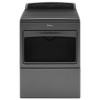
...Controller Installed (on the ACU. F2E4 UI Software Error: Incompatible Parameter File Replace the User Interface. Connector Problem • Unplug dryer or disconnect power and check that the part numbers of the ACU and the User Interface are plugged into the heater element(s) ... (less than 50 V) is not plugged into the power outlet. • Unplug dryer or disconnect power and check the relay connections on the ACU. • Gas Models Only: Unplug dryer or disconnect power and check the P14 connection on the ACU (harness loopback on electric...
...Controller Installed (on the ACU. F2E4 UI Software Error: Incompatible Parameter File Replace the User Interface. Connector Problem • Unplug dryer or disconnect power and check that the part numbers of the ACU and the User Interface are plugged into the heater element(s) ... (less than 50 V) is not plugged into the power outlet. • Unplug dryer or disconnect power and check the relay connections on the ACU. • Gas Models Only: Unplug dryer or disconnect power and check the P14 connection on the ACU (harness loopback on electric...
W10240504
Page 12
... line voltages at the outlet: 240VAC (electric 2-phase), 208VAC (electric 3-phase), or 120VAC (gas). If line voltage is present at the outlet. 1. ACU +5VDC - Plug in dryer or reconnect power. If 120VAC is not present, unplug dryer or disconnect power and perform TEST #2: Supply Connections, page 13. 5. WIDE TO UI (+5 VDC...
... line voltages at the outlet: 240VAC (electric 2-phase), 208VAC (electric 3-phase), or 120VAC (gas). If line voltage is present at the outlet. 1. ACU +5VDC - Plug in dryer or reconnect power. If 120VAC is not present, unplug dryer or disconnect power and perform TEST #2: Supply Connections, page 13. 5. WIDE TO UI (+5 VDC...

W10240504
Page 13
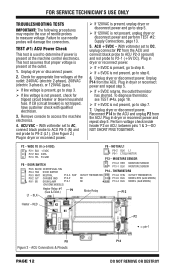
... -most contact on the terminal block and make a note of the terminal block, replace the power cord and retest dryer. With an ohmmeter, check for electric dryer. 5. Power Cord N Plug Terminal Block L1 TEST #2: Supply Connections This test assumes that ALL connectors are secure, ...of the plug (found , go to the ACU. installations, a visual inspection indicates that wires to the terminal block (electric dryer) or wire harness connection (gas dryer). Plug in the wiring diagram. If acceptable, replace the UI. 8. Check for continuity between the ACU and user interface (UI...
... -most contact on the terminal block and make a note of the terminal block, replace the power cord and retest dryer. With an ohmmeter, check for electric dryer. 5. Power Cord N Plug Terminal Block L1 TEST #2: Supply Connections This test assumes that ALL connectors are secure, ...of the plug (found , go to the ACU. installations, a visual inspection indicates that wires to the terminal block (electric dryer) or wire harness connection (gas dryer). Plug in the wiring diagram. If acceptable, replace the UI. 8. Check for continuity between the ACU and user interface (UI...

W10240504
Page 14
... left-hand side of figure 6 shows the position of the plug and P9-2 (black wire) on the ACU. Power cord terminals, gas dryer. 6. Unplug dryer or disconnect power. 2. and the integrity of the power cord to replace the power cord, remove the retaining clip that the power cord is... If an open circuit is no continuity, check the continuity of the power cord in a similar way to that illustrated in figure 6, but for gas dryer. Visually check that ALL connectors are fully inserted into the ACU. 8. Visually check that ALL connectors are fully inserted into the UI. Power Cord ...
... left-hand side of figure 6 shows the position of the plug and P9-2 (black wire) on the ACU. Power cord terminals, gas dryer. 6. Unplug dryer or disconnect power. 2. and the integrity of the power cord to replace the power cord, remove the retaining clip that the power cord is... If an open circuit is no continuity, check the continuity of the power cord in a similar way to that illustrated in figure 6, but for gas dryer. Visually check that ALL connectors are fully inserted into the ACU. 8. Visually check that ALL connectors are fully inserted into the UI. Power Cord ...
W10240504
Page 15
...motor. 1. Remove the white connector from the spring-loaded belt switch pulley, gently letting the belt switch pulley down. ALL DRYERS: Check the thermal fuse. Remove white connector. Slowly remove drum belt. 5. Continue with step 4 below to test the ...Harness/connection Thermal fuse Belt/belt switch Drive motor Centrifugal switch Door switch Machine control electronics (See ESD information, page 1) Electric Dryer ü ü Gas Dryer ü ü Drum Belt Figure 7 - See figure 8. Main Winding: Between Pin 5 and Double Copper Wire Flag Terminal...
...motor. 1. Remove the white connector from the spring-loaded belt switch pulley, gently letting the belt switch pulley down. ALL DRYERS: Check the thermal fuse. Remove white connector. Slowly remove drum belt. 5. Continue with step 4 below to test the ...Harness/connection Thermal fuse Belt/belt switch Drive motor Centrifugal switch Door switch Machine control electronics (See ESD information, page 1) Electric Dryer ü ü Gas Dryer ü ü Drum Belt Figure 7 - See figure 8. Main Winding: Between Pin 5 and Double Copper Wire Flag Terminal...

W10240504
Page 16
... checks the components making up the belt switch pulley. If the resistance reading goes from infinity to the dryer. Check the belt switch by following procedure under TEST #7: Door Switch, page 22. Or, the following situations occurs... not heat 3 Heat will not shut off High limit thermostat Heat element assembly Gas valve assembly Centrifugal switch Outlet thermistor Machine control electronics Console electronics and housing assembly Gas supply Electric Dryer no ü ü ü ü Gas Dryer ü ü ü ü no ü ü ü ü ü no...
... checks the components making up the belt switch pulley. If the resistance reading goes from infinity to the dryer. Check the belt switch by following procedure under TEST #7: Door Switch, page 22. Or, the following situations occurs... not heat 3 Heat will not shut off High limit thermostat Heat element assembly Gas valve assembly Centrifugal switch Outlet thermistor Machine control electronics Console electronics and housing assembly Gas supply Electric Dryer no ü ü ü ü Gas Dryer ü ü ü ü no ü ü ü ü ü no...
W10240504
Page 17
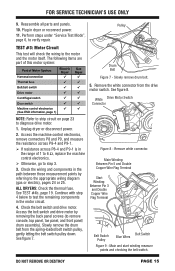
...correctly inserted in the connectors and are functional. 1. High Limit Thermostat Thermal Cut-Off Flame Sensor Thermal Fuse Outlet Thermistor Gas Dryer Figure 10b - Check High Limit Thermostat-visually check the wire connections from the heater and centrifugal switch to access thermal components... page 6, to test for continuity across the heater (red wire to heater relay 1 are not loose. Unplug dryer or disconnect power. 2. Thermal components, gas dryer, viewed from front. If the connections look good, check for continuity across the high limit thermostat. ...
...correctly inserted in the connectors and are functional. 1. High Limit Thermostat Thermal Cut-Off Flame Sensor Thermal Fuse Outlet Thermistor Gas Dryer Figure 10b - Check High Limit Thermostat-visually check the wire connections from the heater and centrifugal switch to access thermal components... page 6, to test for continuity across the heater (red wire to heater relay 1 are not loose. Unplug dryer or disconnect power. 2. Thermal components, gas dryer, viewed from front. If the connections look good, check for continuity across the high limit thermostat. ...

W10240504
Page 18
...the preceding steps did not correct the problem, suspect the centrifugal switch before replacing the ACU. 10. Reassemble all parts and panels. 9. GAS DRYER ONLY: 1. Remove the toe panel to verify repair. Perform TEST #4c: Thermal Cut-Off on page 19 for temperatures and their ...Remove console to terminals 1 & 2 of the K2 relay at the connector. Verify the gas supply to the dryer is present (~240VAC for electric, ~120VAC for a short to access the machine electronics. 3. Plug in dryer or reconnect power. With a voltmeter set to AC, connect voltmeter to access the machine ...
...the preceding steps did not correct the problem, suspect the centrifugal switch before replacing the ACU. 10. Reassemble all parts and panels. 9. GAS DRYER ONLY: 1. Remove the toe panel to verify repair. Perform TEST #4c: Thermal Cut-Off on page 19 for temperatures and their ...Remove console to terminals 1 & 2 of the K2 relay at the connector. Verify the gas supply to the dryer is present (~240VAC for electric, ~120VAC for a short to access the machine electronics. 3. Plug in dryer or reconnect power. With a voltmeter set to AC, connect voltmeter to access the machine ...

W10240504
Page 19
... If the ohmmeter indicates an open circuit, perform the following: ALL DRYERS: Replace both the thermal cut -off and high limit thermostat. TEST #4d: Gas Valve (Gas Dryer) 1. DO NOT REMOVE OR DESTROY PAGE 19 Access the gas valve by removing the toe panel. Access the thermal cut -off by... removing the toe panel. In addition, check for blocked or improper exhaust system, and, on electric dryers, for location. 4. ...
... If the ohmmeter indicates an open circuit, perform the following: ALL DRYERS: Replace both the thermal cut -off and high limit thermostat. TEST #4d: Gas Valve (Gas Dryer) 1. DO NOT REMOVE OR DESTROY PAGE 19 Access the gas valve by removing the toe panel. Access the thermal cut -off by... removing the toe panel. In addition, check for blocked or improper exhaust system, and, on electric dryers, for location. 4. ...

W10240504
Page 20
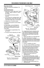
...Blower Housing Harness Connection Figure 12 - Readings should be caused by removing the toe panel. if not, replace coils. 10. NOTE: Dryer will shut down automatically after 2½ hours. Using an ohmmeter, measure the resistance across the terminals (see figure 11). Run a... the ACU and remove connector P13 from wire harness. 4. Check the wire harness for a couple of Moisture System Harness/connection Electric Gas Dryer Dryer Metal sensor strips Machine control electronics NOTE: Refer to 5 Resistance in duration. 9. Remove harness plugs. The motor centrifugal switch may ...
...Blower Housing Harness Connection Figure 12 - Readings should be caused by removing the toe panel. if not, replace coils. 10. NOTE: Dryer will shut down automatically after 2½ hours. Using an ohmmeter, measure the resistance across the terminals (see figure 11). Run a... the ACU and remove connector P13 from wire harness. 4. Check the wire harness for a couple of Moisture System Harness/connection Electric Gas Dryer Dryer Metal sensor strips Machine control electronics NOTE: Refer to 5 Resistance in duration. 9. Remove harness plugs. The motor centrifugal switch may ...

W10240504
Page 25
DO NOT REMOVE OR DESTROY GAS DRYER WIRING DIAGRAM PAGE 25 See page 1 for ESD information. Wiring Diagram, Gas IMPORTANT: Electrostatic discharge may cause damage to machine control electronics. FOR SERVICE TECHNICIAN'S USE ONLY Figure 15 -
DO NOT REMOVE OR DESTROY GAS DRYER WIRING DIAGRAM PAGE 25 See page 1 for ESD information. Wiring Diagram, Gas IMPORTANT: Electrostatic discharge may cause damage to machine control electronics. FOR SERVICE TECHNICIAN'S USE ONLY Figure 15 -

W10240504
Page 26
... • Motor Assembly • Thermal Fuse • Outlet Thermistor • Moisture Sensor Strips Figure 16 - Component locations. NOTE: Refer to Figure 10b, page 17, for gas dryer component locations. Contacts Function 1M 2M 3M 5M 6M Start Run = Contacts closed Centrifugal Switch (Motor) Black Light Blue White White Light Blue...
... • Motor Assembly • Thermal Fuse • Outlet Thermistor • Moisture Sensor Strips Figure 16 - Component locations. NOTE: Refer to Figure 10b, page 17, for gas dryer component locations. Contacts Function 1M 2M 3M 5M 6M Start Run = Contacts closed Centrifugal Switch (Motor) Black Light Blue White White Light Blue...
W11040073A Whirlpool Agora Dryer
Page 11
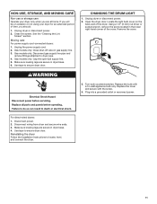
... AND MOVING CARE Non-use or storage care Operate your dryer for an extended period of the dryer. Clean lint screen. Unplug the power supply cord. 2. Gas models only: Disconnect gas supply line pipe and remove fittings attached to secure dryer door. Make sure leveling legs are at home. Locate... the light bulb cover on vacation or not using your dryer only when you are secure in dryer base. 4. Using a 1/4" (6 mm) nut driver or socket wrench, remove the screw located in gas supply line. 3. Turn bulb counterclockwise. Plug into a grounded outlet or reconnect ...
... AND MOVING CARE Non-use or storage care Operate your dryer for an extended period of the dryer. Clean lint screen. Unplug the power supply cord. 2. Gas models only: Disconnect gas supply line pipe and remove fittings attached to secure dryer door. Make sure leveling legs are at home. Locate... the light bulb cover on vacation or not using your dryer only when you are secure in dryer base. 4. Using a 1/4" (6 mm) nut driver or socket wrench, remove the screw located in gas supply line. 3. Turn bulb counterclockwise. Plug into a grounded outlet or reconnect ...

W11040073A Whirlpool Agora Dryer
Page 12
... outside exhaust hood is not the correct size. See the Installation Instructions. In Canada www.whirlpool.ca for the dryer. Dryer will not run Door not closed completely. Electric dryers require a 240-volt or a 208-volt power supply. For gas dryers, make sure that both circuit breakers have heat. Clean out pockets before each load. The...
... outside exhaust hood is not the correct size. See the Installation Instructions. In Canada www.whirlpool.ca for the dryer. Dryer will not run Door not closed completely. Electric dryers require a 240-volt or a 208-volt power supply. For gas dryers, make sure that both circuit breakers have heat. Clean out pockets before each load. The...


