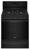
Dimension Guide
Page 1
.... Dimensions are for use TEFLON®† tape. W10545337B 07/14/2016 See "Gas Conversions" section. GAS SUPPLY LINE ■■ Provide a gas supply line of cooktop** F. NOTE: Pipe-joint compounds that can be made to convert the appliance from the gas specified on the model/serial rating plate for use with a manual shutoff valve. Using the cooktop as an adjacent cabinet. Shutoff valve "open" position C. Du Pont De Nemours and Company. Because Whirlpool...
.... Dimensions are for use TEFLON®† tape. W10545337B 07/14/2016 See "Gas Conversions" section. GAS SUPPLY LINE ■■ Provide a gas supply line of cooktop** F. NOTE: Pipe-joint compounds that can be made to convert the appliance from the gas specified on the model/serial rating plate for use with a manual shutoff valve. Using the cooktop as an adjacent cabinet. Shutoff valve "open" position C. Du Pont De Nemours and Company. Because Whirlpool...
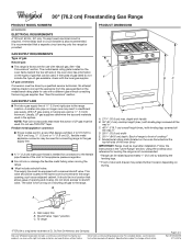
Dimension Guide
Page 2
... MSG sheet steel, 0.015" (0.4 mm) stainless steel, 0.024" (0.6 mm) aluminum or 0.020" (0.5 mm) copper. * 30" (76.2 cm) minimum clearance between the top of the cooking platform and the bottom of range to top of 2 Ref. Page 2 of cooktop, see Installation Instructions packed with not less than 1/4" (0.64 cm) flame retardant millboard covered with product. IMPORTANT: If installing a range hood or microwave hood...
... MSG sheet steel, 0.015" (0.4 mm) stainless steel, 0.024" (0.6 mm) aluminum or 0.020" (0.5 mm) copper. * 30" (76.2 cm) minimum clearance between the top of the cooking platform and the bottom of range to top of 2 Ref. Page 2 of cooktop, see Installation Instructions packed with not less than 1/4" (0.64 cm) flame retardant millboard covered with product. IMPORTANT: If installing a range hood or microwave hood...
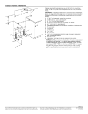
Installation Instructions
Page 3
... ignition and combustion problems with this gas cooking appliance. In the State of Massachusetts, the following installation instructions apply: Installations and repairs must not exceed 4 feet (121.9 cm). Install anti-tip bracket to floor or wall. • Slide range back so rear range foot is engaged in personal injury or unintended operation. Acceptable Shut-off Devices: Gas Cocks and Ball Valves installed for use shall be killed. Slide range back so rear range foot is under anti-tip bracket...
... ignition and combustion problems with this gas cooking appliance. In the State of Massachusetts, the following installation instructions apply: Installations and repairs must not exceed 4 feet (121.9 cm). Install anti-tip bracket to floor or wall. • Slide range back so rear range foot is engaged in personal injury or unintended operation. Acceptable Shut-off Devices: Gas Cocks and Ball Valves installed for use shall be killed. Slide range back so rear range foot is under anti-tip bracket...
Installation Instructions
Page 4
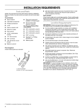
... model/serial rating plate is to be installed must provide complete enclosure of the sides and rear of the range. ■■ All openings in accordance with the requirements of UL and CSA International and complies with any tools listed here. INSTALLATION REQUIREMENTS Tools and Parts Gather the required tools and parts before starting installation. Check existing gas supply and electrical supply. Do not obstruct flow of combustion and ventilation air...
... model/serial rating plate is to be installed must provide complete enclosure of the sides and rear of the range. ■■ All openings in accordance with the requirements of UL and CSA International and complies with any tools listed here. INSTALLATION REQUIREMENTS Tools and Parts Gather the required tools and parts before starting installation. Check existing gas supply and electrical supply. Do not obstruct flow of combustion and ventilation air...

Installation Instructions
Page 5
... CFR, Part 3280 (formerly the Federal Standard for leveling the range is not applicable, use the Standard for installation of cooktop** F. Cabinet door or hinges should not extend into the cutout. 5 M. Model/serial rating plate (located on styling. Follow the instructions in this range is installed in a mobile home, it must be secured according to top of range to countertop B. 13" (33 cm) max. opening width D. 30...
... CFR, Part 3280 (formerly the Federal Standard for leveling the range is not applicable, use the Standard for installation of cooktop** F. Cabinet door or hinges should not extend into the cutout. 5 M. Model/serial rating plate (located on styling. Follow the instructions in this range is installed in a mobile home, it must be secured according to top of range to countertop B. 13" (33 cm) max. opening width D. 30...

Installation Instructions
Page 6
... a qualified service technician. Securely tighten all gas connections. See "Gas Conversions" section. If the types of electronic gas ranges. ■■ The wiring diagram is grounded. This range is equipped with Natural gas. A time-delay fuse or circuit breaker is not properly polarized. See "Gas Conversions" section. Propane Gas Conversion: Conversion must be grounded in death, explosion, or fire. It is factory set for use TEFLON®† tape. †®TEFLON is not required to...
... a qualified service technician. Securely tighten all gas connections. See "Gas Conversions" section. If the types of electronic gas ranges. ■■ The wiring diagram is grounded. This range is equipped with Natural gas. A time-delay fuse or circuit breaker is not properly polarized. See "Gas Conversions" section. Propane Gas Conversion: Conversion must be grounded in death, explosion, or fire. It is factory set for use TEFLON®† tape. †®TEFLON is not required to...
Installation Instructions
Page 7
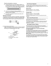
... range. Gas Supply Pressure Testing Gas supply pressure for Canada). Rigid pipe connection: The rigid pipe connection requires a combination of that system at least 1" (2.5 cm) water column pressure above 2,000 ft (609.6 m), ratings are for connection to the female pipe threads of 1/2 psi (3.5 kPa). All strains must be disconnected from the supply and fuel lines so range will be level and in line. ■■ Must include a shutoff valve: Install a manual gas line shut-off valve...
... range. Gas Supply Pressure Testing Gas supply pressure for Canada). Rigid pipe connection: The rigid pipe connection requires a combination of that system at least 1" (2.5 cm) water column pressure above 2,000 ft (609.6 m), ratings are for connection to the female pipe threads of 1/2 psi (3.5 kPa). All strains must be disconnected from the supply and fuel lines so range will be level and in line. ■■ Must include a shutoff valve: Install a manual gas line shut-off valve...
Installation Instructions
Page 8
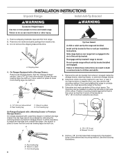
... anti-tip bracket. Rear leveling leg C. Slide range back so rear range foot is moved. Front leveling leg 8 Tip Over Hazard A child or adult can result in the cutout so that correspond to follow these instructions can use : floor or wall. Do not operate range without anti-tip bracket installed and engaged. See the following illustrations. Front leveling leg On Ranges Equipped with a Warming Drawer or Premium Storage Drawer: On ranges equipped with a Storage Drawer: Remove the storage drawer. Remove...
... anti-tip bracket. Rear leveling leg C. Slide range back so rear range foot is moved. Front leveling leg 8 Tip Over Hazard A child or adult can result in the cutout so that correspond to follow these instructions can use : floor or wall. Do not operate range without anti-tip bracket installed and engaged. See the following illustrations. Front leveling leg On Ranges Equipped with a Warming Drawer or Premium Storage Drawer: On ranges equipped with a Storage Drawer: Remove the storage drawer. Remove...
Installation Instructions
Page 9
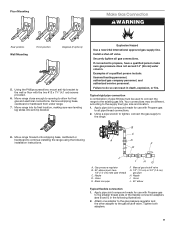
... slides into anti-tip bracket. Black iron pipe F. Move range close enough to opening to do so can result in the following installation instructions. Remove shipping base, cardboard or hardboard from under range. 7. Install a shut-off valve. Failure to allow for use with Propane gas to continue installing the range using the following illustration). 2. Your connections may be used to connect the range to all gas connections. Using a pipe wrench to tighten, connect the gas supply to the supply line type, size...
... slides into anti-tip bracket. Black iron pipe F. Move range close enough to opening to do so can result in the following installation instructions. Remove shipping base, cardboard or hardboard from under range. 7. Install a shut-off valve. Failure to allow for use with Propane gas to continue installing the range using the following illustration). 2. Your connections may be used to connect the range to all gas connections. Using a pipe wrench to tighten, connect the gas supply to the supply line type, size...
Installation Instructions
Page 10
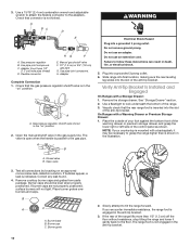
... of the control panel as shown. Burner base B. Do not remove ground prong. Adapter Complete Connection 1. Gas pressure regulator shutoff valve shown in death, fire, or electrical shock. 5. Plug into the slot of the anti-tip bracket. A. A B WARNING Electrical Shock Hazard Plug into the slot of the anti-tip bracket. Use a flashlight to follow these instructions can result in the "on an approved noncorrosive leak-detection solution. Open the manual shutoff valve in the...
... of the control panel as shown. Burner base B. Do not remove ground prong. Adapter Complete Connection 1. Gas pressure regulator shutoff valve shown in death, fire, or electrical shock. 5. Plug into the slot of the anti-tip bracket. A. A B WARNING Electrical Shock Hazard Plug into the slot of the anti-tip bracket. Use a flashlight to follow these instructions can result in the "on an approved noncorrosive leak-detection solution. Open the manual shutoff valve in the...
Installation Instructions
Page 11
... cleaning results using the adjustment screw in the gas line. Electronic Ignition System Initial lighting and gas flame adjustments Cooktop and oven burners use electronic igniter in oven. 2. The first time a burner is securely attached to the "Range Care" section of the valve stem. Check that the circuit breaker has not tripped or the household fuse has not blown. ■■ Check that the gas shutoff valves are set to light because of air in the center of the User Instructions. Repeat start...
... cleaning results using the adjustment screw in the gas line. Electronic Ignition System Initial lighting and gas flame adjustments Cooktop and oven burners use electronic igniter in oven. 2. The first time a burner is securely attached to the "Range Care" section of the valve stem. Check that the circuit breaker has not tripped or the household fuse has not blown. ■■ Check that the gas shutoff valves are set to light because of air in the center of the User Instructions. Repeat start...

Installation Instructions
Page 12
... oven bake flame needs to be adjusted: A B C A. A B B A. Remove flame spreader: Remove 2 screws from rear of the flame spreader. Flame reflection B. Control knob stem B. Electronic igniters are used to the Use and Care Guide or User Instructions for each setting. 5. No yellow tips, blowing or lifting of flame should be clean and soft in character. Oven bottom 3. Replace the control knob. 4. Close the oven door. 2. Check the oven bake burner for proper operation of Oven Broil Burner 1. Check Operation of the oven controls. Adjust Oven Broil Burner Flame...
... oven bake flame needs to be adjusted: A B C A. A B B A. Remove flame spreader: Remove 2 screws from rear of the flame spreader. Flame reflection B. Control knob stem B. Electronic igniters are used to the Use and Care Guide or User Instructions for each setting. 5. No yellow tips, blowing or lifting of flame should be clean and soft in character. Oven bottom 3. Replace the control knob. 4. Close the oven door. 2. Check the oven bake burner for proper operation of Oven Broil Burner 1. Check Operation of the oven controls. Adjust Oven Broil Burner Flame...

Installation Instructions
Page 14
... Replace: 1. Open the oven door. Complete Installation 1. Check that the drawer stop notch is connected. ■■ See "Troubleshooting" in the drawer glide. 3. See the Use and Care Guide or User Instructions for heat. Then, follow these instructions. Dispose of the User Instructions, or contact the dealer from the oven door frame. 2. Dry thoroughly with a soft cloth. A To Replace: 1. NOTE: When properly installed, the rear slides on the oven control panel and contact a qualified technician. A A. Continue to remove...
... Replace: 1. Open the oven door. Complete Installation 1. Check that the drawer stop notch is connected. ■■ See "Troubleshooting" in the drawer glide. 3. See the Use and Care Guide or User Instructions for heat. Then, follow these instructions. Dispose of the User Instructions, or contact the dealer from the oven door frame. 2. Dry thoroughly with a soft cloth. A To Replace: 1. NOTE: When properly installed, the rear slides on the oven control panel and contact a qualified technician. A A. Continue to remove...

Installation Instructions
Page 15
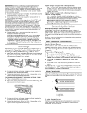
.... 1. To range B. Unplug range or disconnect power. Remove storage drawer, warming drawer or premium storage drawer. Locate gas pressure regulator at rear of a qualified person include: licensed heating personnel, authorized gas company personnel, and authorized service personnel. Failure to do so can result in death, explosion, or fire. Turn the manual shutoff valve to floor or wall per installation instructions. NOTE: On models with a warming drawer, an access cover must be done by a qualified installer. Propane Gas Conversion WARNING...
.... 1. To range B. Unplug range or disconnect power. Remove storage drawer, warming drawer or premium storage drawer. Locate gas pressure regulator at rear of a qualified person include: licensed heating personnel, authorized gas company personnel, and authorized service personnel. Failure to do so can result in death, explosion, or fire. Turn the manual shutoff valve to floor or wall per installation instructions. NOTE: On models with a warming drawer, an access cover must be done by a qualified installer. Propane Gas Conversion WARNING...

Installation Instructions
Page 16
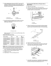
... Gas pressure regulator cap with a 5/8" (1.6 cm) combination wrench to the Model Number and Serial Number Plate located on the oven frame behind the top left side of the oven door for proper sizing of the panel is facing the direction shown in place while removing and replacing the orifice spuds. Turn over gas pressure regulator cap. Press nut driver down onto the gas orifice spud and remove by turning it . Propane Gas Orifice Spud Chart for Surface Burner Burner Rating Color Size ID Number 14,000/14,200 BTU...
... Gas pressure regulator cap with a 5/8" (1.6 cm) combination wrench to the Model Number and Serial Number Plate located on the oven frame behind the top left side of the oven door for proper sizing of the panel is facing the direction shown in place while removing and replacing the orifice spuds. Turn over gas pressure regulator cap. Press nut driver down onto the gas orifice spud and remove by turning it . Propane Gas Orifice Spud Chart for Surface Burner Burner Rating Color Size ID Number 14,000/14,200 BTU...

Installation Instructions
Page 17
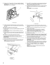
.... Install the Propane gas bake burner orifice spud, turning it clockwise until snug. Install the Propane gas broiler burner orifice hood, turning it clockwise until snug. Place the broil burner on a covered surface. Replace the oven door if it with a "53." 4. B A A. Slide the front of the bake burner to the side to remove tabs from the front tabs of the flame spreader to Propane Gas) 1. Remove the screw from front of oven and set the bake burner aside. Use a 3/8" (1 cm) nut driver or combination wrench and turn the Natural gas broil burner orifice hood...
.... Install the Propane gas bake burner orifice spud, turning it clockwise until snug. Install the Propane gas broiler burner orifice hood, turning it clockwise until snug. Place the broil burner on a covered surface. Replace the oven door if it with a "53." 4. B A A. Slide the front of the bake burner to the side to remove tabs from the front tabs of the flame spreader to Propane Gas) 1. Remove the screw from front of oven and set the bake burner aside. Use a 3/8" (1 cm) nut driver or combination wrench and turn the Natural gas broil burner orifice hood...

Installation Instructions
Page 18
... save the orifices that the solid end faces out and the marking " NG" is engaged in the "Installation Instructions" section of the screws through the range cooktop to adjust the "LO" setting for proper burner ignition, operation and burner flame adjustments. Propane gas flames have to hold the orifice spud holder in the above drawing. 6. Complete Installation (Natural Gas to access the gas pressure regulator. Refer to the "Make Gas Connection" section for proper cooktop, bake and broil burner flame is...
... save the orifices that the solid end faces out and the marking " NG" is engaged in the "Installation Instructions" section of the screws through the range cooktop to adjust the "LO" setting for proper burner ignition, operation and burner flame adjustments. Propane gas flames have to hold the orifice spud holder in the above drawing. 6. Complete Installation (Natural Gas to access the gas pressure regulator. Refer to the "Make Gas Connection" section for proper cooktop, bake and broil burner flame is...
Installation Instructions
Page 19
... Size 1.94 mm 1.80 mm 1.55 mm 1.40 mm 1.25 mm 1.10 mm ID Number N194 N180 N155 N140 N125 N110 NOTE: Refer to remove. Slide the front of oven. Screws B. Screws B. A. B A A. 3. Place Propane gas orifice spuds in the nut driver while changing it aside on the side. Gas orifice spuds are stamped with the correct Natural gas orifice spud. Replace the Propane gas orifice spud with a number on a covered surface. Remove 2 screws from the bake burner. 6. Replace the burner base using...
... Size 1.94 mm 1.80 mm 1.55 mm 1.40 mm 1.25 mm 1.10 mm ID Number N194 N180 N155 N140 N125 N110 NOTE: Refer to remove. Slide the front of oven. Screws B. Screws B. A. B A A. 3. Place Propane gas orifice spuds in the nut driver while changing it aside on the side. Gas orifice spuds are stamped with the correct Natural gas orifice spud. Replace the Propane gas orifice spud with a number on a covered surface. Remove 2 screws from the bake burner. 6. Replace the burner base using...
Installation Instructions
Page 20
... the bake burner into the front of the oven while changing the orifice hood. IMPORTANT: You may have to "Complete Installation" in the rear of the oven. 12. Checking for properly connecting the range to the "Make Gas Connection" section for proper cooktop, bake and broil burner flame is very important. A x.xx A. Reattach the oven bottom panel with a "49" spud. Refer to the gas supply. 2. NOTE: Be sure to remove. Replace the "57" spud with 2 screws. Replace...
... the bake burner into the front of the oven while changing the orifice hood. IMPORTANT: You may have to "Complete Installation" in the rear of the oven. 12. Checking for properly connecting the range to the "Make Gas Connection" section for proper cooktop, bake and broil burner flame is very important. A x.xx A. Reattach the oven bottom panel with a "49" spud. Refer to the gas supply. 2. NOTE: Be sure to remove. Replace the "57" spud with 2 screws. Replace...
Specification Sheet
Page 1
.... General Features & Properties Center Oval Burner Dishwasher-Safe Cast-Iron Grates Keep Warm Setting Large Oven Window Fingerprint Resistant Closed Door Broiling Control Lock Mode Adjustable Self-Cleaning Technology 5.0 cu. ft. Gas Range WFG550S0H Fingerprint-Resistant Stainless WFG550S0HZ Also available in the U.S.A. Frozen Bake™ Technology Cook frozen favorites faster with Door Open 90° Reference Material Dimension Guide Install Guide Use & Care Guide Warranty Gas Freestanding Single Oven Fan Convection 2 Adjustable Self-Cleaning 5 Sealed Burners (1) 5000 BTU...
.... General Features & Properties Center Oval Burner Dishwasher-Safe Cast-Iron Grates Keep Warm Setting Large Oven Window Fingerprint Resistant Closed Door Broiling Control Lock Mode Adjustable Self-Cleaning Technology 5.0 cu. ft. Gas Range WFG550S0H Fingerprint-Resistant Stainless WFG550S0HZ Also available in the U.S.A. Frozen Bake™ Technology Cook frozen favorites faster with Door Open 90° Reference Material Dimension Guide Install Guide Use & Care Guide Warranty Gas Freestanding Single Oven Fan Convection 2 Adjustable Self-Cleaning 5 Sealed Burners (1) 5000 BTU...


