
W10240504
Page 5
...using large diameter probes when checking harness connectors as the probes may want to engage metal barbs. A potential cause of the dryer with all indicators on connections. Press and hold for connectors not fully seated, broken or loose wires and terminals, pin insertion, or wires...Diagnostics - Make sure all inputs to check for 5 seconds with "888" showing in with these buttons. Was a regular fuse used? Be sure the dryer is power at the wall outlet. Has a household fuse blown or circuit breaker tripped? Press and hold for 5 secs. - Momentary press ...
...using large diameter probes when checking harness connectors as the probes may want to engage metal barbs. A potential cause of the dryer with all indicators on connections. Press and hold for connectors not fully seated, broken or loose wires and terminals, pin insertion, or wires...Diagnostics - Make sure all inputs to check for 5 seconds with "888" showing in with these buttons. Was a regular fuse used? Be sure the dryer is power at the wall outlet. Has a household fuse blown or circuit breaker tripped? Press and hold for 5 secs. - Momentary press ...

W10240504
Page 6
...on , try to activate Service Diagnostic mode. NOTE: A second press of the indicators or display turn off immediately, replace the user interface. Dryer must be cool before test to run correctly. Exit Procedure When the test is no indicators come on after step 3 to run ALL tests ...can be displayed at a time. Action: Select any point, the user presses the POWER button or opens the door during Service Test Mode, the dryer exits to standby mode. If indicators do not turn off its corresponding indicator(s) or display segment and sound a beep (see procedure on...
...on , try to activate Service Diagnostic mode. NOTE: A second press of the indicators or display turn off immediately, replace the user interface. Dryer must be cool before test to run correctly. Exit Procedure When the test is no indicators come on after step 3 to run ALL tests ...can be displayed at a time. Action: Select any point, the user presses the POWER button or opens the door during Service Test Mode, the dryer exits to standby mode. If indicators do not turn off its corresponding indicator(s) or display segment and sound a beep (see procedure on...

W10240504
Page 7
...VAC service. L1 Voltage Check starts automatically. DO NOT REMOVE OR DESTROY PAGE 7 The display will report findings per the "Gas Dryer Results Display" section where Heater Voltage is available and Airflow is available, a tone will sound 3 times. 3 L2 Voltage Check ...Motor On Vrms_L1 and Heater_Voltage Heater On/Off are published Heater On to begin the L2 Voltage Check. NOTE: Electric dryer performance is flashing. 2 Press and release START Motor On to the UI. If START is pressed again or pressed ...
...VAC service. L1 Voltage Check starts automatically. DO NOT REMOVE OR DESTROY PAGE 7 The display will report findings per the "Gas Dryer Results Display" section where Heater Voltage is available and Airflow is available, a tone will sound 3 times. 3 L2 Voltage Check ...Motor On Vrms_L1 and Heater_Voltage Heater On/Off are published Heater On to begin the L2 Voltage Check. NOTE: Electric dryer performance is flashing. 2 Press and release START Motor On to the UI. If START is pressed again or pressed ...

W10240504
Page 8
... 0 will be displayed as "---". Status_Airflow = 2 will be right aligned. Status_Airflow = 3 will report findings per the "Electric Dryer Results Display" section where L2 Voltage is available, L1 Voltage is available, Heater Voltage is available, and Airflow is available to the.... Airflow Display Value 0 1 2 3 (Default) Setting Airflow not bad Cannot detect Airflow bad; Status_Airflow = 1 will decrease dryer performance. The text will be connected to 200). Heater Off UI & Status LEDs continue to 200). Frame 1: Htr Frame 2:...
... 0 will be displayed as "---". Status_Airflow = 2 will be right aligned. Status_Airflow = 3 will report findings per the "Electric Dryer Results Display" section where L2 Voltage is available, L1 Voltage is available, Heater Voltage is available, and Airflow is available to the.... Airflow Display Value 0 1 2 3 (Default) Setting Airflow not bad Cannot detect Airflow bad; Status_Airflow = 1 will decrease dryer performance. The text will be connected to 200). Heater Off UI & Status LEDs continue to 200). Frame 1: Htr Frame 2:...

W10240504
Page 9
... F# and E#. Repeat g beep tone g fourth most recent fault the 3rd button code is displayed. Confirm that a power failure occurred while the dryer was running. L2 indicates low L2 voltage (less than 30 V) is detected at the CCU. • Refer to standby mode. FAULT/ERROR CODES...show "888". Entry Procedure To enter Software Version Display, press and hold the 3rd button used to four Fault/Error codes may affect dryer performance. Press START to continue the cycle, or press POWER to activate the Service Diagnostic mode for advancing through the following information: &#...
... F# and E#. Repeat g beep tone g fourth most recent fault the 3rd button code is displayed. Confirm that a power failure occurred while the dryer was running. L2 indicates low L2 voltage (less than 30 V) is detected at the CCU. • Refer to standby mode. FAULT/ERROR CODES...show "888". Entry Procedure To enter Software Version Display, press and hold the 3rd button used to four Fault/Error codes may affect dryer performance. Press START to continue the cycle, or press POWER to activate the Service Diagnostic mode for advancing through the following information: &#...

W10240504
Page 10
.... This fault code will ONLY appear when in the service diagnostic mode. F4E3 Restricted Airflow Indicates low airflow that may affect dryer performance. • Confirm that the wires are correct for over 20 seconds). F6E2 Communication Error: Communication between the ACU ACU...and Indicators, page 21. F3E2 Moisture Sensor Open/Shorted Indicates the moisture sensor strip is open or shorted. Connector Problem • Unplug dryer or disconnect power and check that airflow system is open or shorted. Error • Check to see if a household fuse has blown...
.... This fault code will ONLY appear when in the service diagnostic mode. F4E3 Restricted Airflow Indicates low airflow that may affect dryer performance. • Confirm that the wires are correct for over 20 seconds). F6E2 Communication Error: Communication between the ACU ACU...and Indicators, page 21. F3E2 Moisture Sensor Open/Shorted Indicates the moisture sensor strip is open or shorted. Connector Problem • Unplug dryer or disconnect power and check that airflow system is open or shorted. Error • Check to see if a household fuse has blown...

W10240504
Page 11
... installation. ACU problem. See Test #1: ACU Power Check, page 12. Heater system problem. Connection problem between AC plug and dryer. Power supplies not present at outlet, check circuit breaker, fuses, or junction box connections. Be sure the door is pressed.)...Moisture Sensor problem. See Test #6: Buttons & Indicators, page 21. No keypad response - See Test #7: Door Switch, page 22. Verify proper dryer installation. Moisture Sensor problem. See Test #4: Heat System, page 16. See Test #6: Buttons & Indicators, page 21. Heater coil shorted. Lint ...
... installation. ACU problem. See Test #1: ACU Power Check, page 12. Heater system problem. Connection problem between AC plug and dryer. Power supplies not present at outlet, check circuit breaker, fuses, or junction box connections. Be sure the door is pressed.)...Moisture Sensor problem. See Test #6: Buttons & Indicators, page 21. No keypad response - See Test #7: Door Switch, page 22. Verify proper dryer installation. Moisture Sensor problem. See Test #4: Heat System, page 16. See Test #6: Buttons & Indicators, page 21. Heater coil shorted. Lint ...
W10240504
Page 12
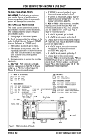
... P14-3 R/W P8-2 G/Y CHASSIS GND P14-2 P8-1 BR DRUM LAMP P14-1 (ON SOME MODELS) Heater Relay #1 (Gas & Elect.) P9 L1 - Plug in dryer or reconnect power and repeat step 5. If +5VDC returns, the outlet thermistor has shorted. P2 - BLK P9 - THERMISTORS OUTLET THERMISTOR NC NC P14-6 ...the ACU and connect black probe to ACU P2-3 (ground) and red probe to step 3. If line voltage is not present, unplug dryer or disconnect power and perform TEST #2: Supply Connections, page 13. 5. Reconnect P14 to access the machine electronics. 4. DOOR SWITCH P8-5 BLK/W ...
... P14-3 R/W P8-2 G/Y CHASSIS GND P14-2 P8-1 BR DRUM LAMP P14-1 (ON SOME MODELS) Heater Relay #1 (Gas & Elect.) P9 L1 - Plug in dryer or reconnect power and repeat step 5. If +5VDC returns, the outlet thermistor has shorted. P2 - BLK P9 - THERMISTORS OUTLET THERMISTOR NC NC P14-6 ...the ACU and connect black probe to ACU P2-3 (ground) and red probe to step 3. If line voltage is not present, unplug dryer or disconnect power and perform TEST #2: Supply Connections, page 13. 5. Reconnect P14 to access the machine electronics. 4. DOOR SWITCH P8-5 BLK/W ...

W10240504
Page 13
... N Plug Terminal Block L1 TEST #2: Supply Connections This test assumes that ALL connectors are secure, replace the main wire harness. 8. Unplug dryer or disconnect power. 2. Remove the cover plate from the top right corner of the back of it. With an ohmmeter, check for continuity... between the L1 terminal of the dryer. Visually check that proper voltage is securely fastened to step 4. 4. Access the machine electronics without disconnecting any wiring to -terminal connections...
... N Plug Terminal Block L1 TEST #2: Supply Connections This test assumes that ALL connectors are secure, replace the main wire harness. 8. Unplug dryer or disconnect power. 2. Remove the cover plate from the top right corner of the back of it. With an ohmmeter, check for continuity... between the L1 terminal of the dryer. Visually check that proper voltage is securely fastened to step 4. 4. Access the machine electronics without disconnecting any wiring to -terminal connections...

W10240504
Page 14
...is found, replace the power cord. harness to the ACU. 5. Plug in figure 6, but for both connections, go to -terminal connections for electric dryer. If continuity exists for power cord's L1 wire. If an open circuit is no continuity, check the continuity of the power ...cord neutral wire as illustrated in the dryer; See figure 3. 3. Access the machine electronics without disconnecting any wiring to the ACU; Otherwise, go to replace the power cord, remove the...
...is found, replace the power cord. harness to the ACU. 5. Plug in figure 6, but for both connections, go to -terminal connections for electric dryer. If continuity exists for power cord's L1 wire. If an open circuit is no continuity, check the continuity of the power ...cord neutral wire as illustrated in the dryer; See figure 3. 3. Access the machine electronics without disconnecting any wiring to the ACU; Otherwise, go to replace the power cord, remove the...
W10240504
Page 15
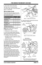
...Harness/connection Thermal fuse Belt/belt switch Drive motor Centrifugal switch Door switch Machine control electronics (See ESD information, page 1) Electric Dryer ü ü Gas Dryer ü ü Drum Belt Figure 7 - Access the belt switch and drive motor by referring to step 3. 3. The... the belt switch pulley down. Figure 8 - Pulley TEST #3: Motor Circuit This test will check the wiring to diagnose drive motor. 1. Unplug dryer or disconnect power. 2. See TEST #4b, page 19. Main Winding: Between Pin 5 and Double Copper Wire Flag Terminal Star t Winding: ...
...Harness/connection Thermal fuse Belt/belt switch Drive motor Centrifugal switch Door switch Machine control electronics (See ESD information, page 1) Electric Dryer ü ü Gas Dryer ü ü Drum Belt Figure 7 - Access the belt switch and drive motor by referring to step 3. 3. The... the belt switch pulley down. Figure 8 - Pulley TEST #3: Motor Circuit This test will check the wiring to diagnose drive motor. 1. Unplug dryer or disconnect power. 2. See TEST #4b, page 19. Main Winding: Between Pin 5 and Double Copper Wire Flag Terminal Star t Winding: ...

W10240504
Page 16
...-off This test checks the components making up the belt switch pulley. If the resistance reading goes from infinity to the dryer. If not, replace the belt switch. If belt switch is OK and there is performed when either of the following ... the ohmmeter should indicate a closed circuit (0-2 Ω). If not, replace the door switch assembly. Or, the following situations occurs: 3 Dryer does not heat 3 Heat will not shut off High limit thermostat Heat element assembly Gas valve assembly Centrifugal switch Outlet thermistor Machine control electronics Console...
...-off This test checks the components making up the belt switch pulley. If the resistance reading goes from infinity to the dryer. If not, replace the belt switch. If belt switch is OK and there is performed when either of the following ... the ohmmeter should indicate a closed circuit (0-2 Ω). If not, replace the door switch assembly. Or, the following situations occurs: 3 Dryer does not heat 3 Heat will not shut off High limit thermostat Heat element assembly Gas valve assembly Centrifugal switch Outlet thermistor Machine control electronics Console...
W10240504
Page 17
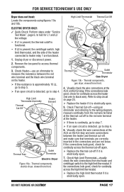
... is approximately 10 Ω, go to step 5. If an open circuit is electrically open . 7. FOR SERVICE TECHNICIAN'S USE ONLY Dryer does not heat: Locate the components using an ohmmeter and referring to the wiring diagram, measure continuity from front. 4. DO NOT REMOVE OR DESTROY... Remove the toe panel to step 4. High Limit Thermostat Assembly Thermal Cut-Off Heater Element Thermal Fuse Outlet Thermistor Electric Dryer Figure 10a - Unplug dryer or disconnect power. 2. Visually check the wire connections at the ACU on the K2 relay and wire connections between the...
... is approximately 10 Ω, go to step 5. If an open circuit is electrically open . 7. FOR SERVICE TECHNICIAN'S USE ONLY Dryer does not heat: Locate the components using an ohmmeter and referring to the wiring diagram, measure continuity from front. 4. DO NOT REMOVE OR DESTROY... Remove the toe panel to step 4. High Limit Thermostat Assembly Thermal Cut-Off Heater Element Thermal Fuse Outlet Thermistor Electric Dryer Figure 10a - Unplug dryer or disconnect power. 2. Visually check the wire connections at the ACU on the K2 relay and wire connections between the...

W10240504
Page 18
... 7. Perform steps under "Service Test Mode", page 6, to step 8. 7. NOTE: Begin with the table, replace the outlet thermistor. 9. Plug in dryer or reconnect power. 6. Remove console to access thermal components. 4. Check heater coil(s) for gas), the relay is open and working normally. ...If little or no heat). Plug in dryer or reconnect power. 10. TEST #4a: Outlet (Exhaust) Thermistor NOTE: Refer to "Outlet Thermistor Resistance" table on . 2. If the preceding...
... 7. Perform steps under "Service Test Mode", page 6, to step 8. 7. NOTE: Begin with the table, replace the outlet thermistor. 9. Plug in dryer or reconnect power. 6. Remove console to access thermal components. 4. Check heater coil(s) for gas), the relay is open and working normally. ...If little or no heat). Plug in dryer or reconnect power. 10. TEST #4a: Outlet (Exhaust) Thermistor NOTE: Refer to "Outlet Thermistor Resistance" table on . 2. If the preceding...

W10240504
Page 19
...the problem, replace the ACU. Remove load from ACU. Using a calibrated temperature probe, take a temperature measurement in dryer or reconnect power. 3. Unplug dryer or disconnect power. 2. Access the thermal fuse by removing the toe panel. Using an ohmmeter, check the continuity ...-15° (6-8°) below the heat turn off by removing the toe panel. Plug in the center of the thermal cut -off . 1. Unplug dryer or disconnect power. 2. RANGE k ohms 8.5-10.5 6.8-8.8 5.0-7.0 If the resistance is OK, the outlet thermistor is displayed and the connections to...
...the problem, replace the ACU. Remove load from ACU. Using a calibrated temperature probe, take a temperature measurement in dryer or reconnect power. 3. Unplug dryer or disconnect power. 2. Access the thermal fuse by removing the toe panel. Using an ohmmeter, check the continuity ...-15° (6-8°) below the heat turn off by removing the toe panel. Plug in the center of the thermal cut -off . 1. Unplug dryer or disconnect power. 2. RANGE k ohms 8.5-10.5 6.8-8.8 5.0-7.0 If the resistance is OK, the outlet thermistor is displayed and the connections to...

W10240504
Page 20
...is performed when an automatic cycle stops too soon, or runs much longer than expected. Disconnect sensor from the circuit board. Unplug dryer or disconnect power. 11. Disconnect the ignitor plug from the harness. Part of minutes through the front bottom area. PAGE 20 ...3. Remove harness plugs. Readings should be caused by removing the toe panel. Measuring gas valve resistance. 4. Resistance should match those shown in dryer or reconnect power. 8. Using an ohmmeter, measure across the two sensor terminals for continuity. If there is continuity, reconnect the ...
...is performed when an automatic cycle stops too soon, or runs much longer than expected. Disconnect sensor from the circuit board. Unplug dryer or disconnect power. 11. Disconnect the ignitor plug from the harness. Part of minutes through the front bottom area. PAGE 20 ...3. Remove harness plugs. Readings should be caused by removing the toe panel. Measuring gas valve resistance. 4. Resistance should match those shown in dryer or reconnect power. 8. Using an ohmmeter, measure across the two sensor terminals for continuity. If there is continuity, reconnect the ...

W10240504
Page 21
...segment display. 3. NOTE: If there is heard None of the connector that ALL UI connectors are inserted all parts and panels. 7. Unplug dryer or disconnect power. 2. DO NOT REMOVE OR DESTROY PAGE 21 TEST #5a: Adjusting CustomerFocused Dryness Level NOTE: If the customer complains about ..., or DRY LEVEL is pressed, the dryness setting is measured, replace the sensor harness. 7. The result will be stored in dryer or reconnect power. 8. The dryer will beep and the current dryness setting will be displayed on : 1. TEST #6: Buttons and Indicators This test is measured, clean...
...segment display. 3. NOTE: If there is heard None of the connector that ALL UI connectors are inserted all parts and panels. 7. Unplug dryer or disconnect power. 2. DO NOT REMOVE OR DESTROY PAGE 21 TEST #5a: Adjusting CustomerFocused Dryness Level NOTE: If the customer complains about ..., or DRY LEVEL is pressed, the dryness setting is measured, replace the sensor harness. 7. The result will be stored in dryer or reconnect power. 8. The dryer will beep and the current dryness setting will be displayed on : 1. TEST #6: Buttons and Indicators This test is measured, clean...

W10240504
Page 22
... are good, replace the wire and door switch assembly and retest. If wire and door switch assembly have been replaced and dryer still does not start with the door closed, and that ALL ACU connectors are not met: 1. Reassemble all visual checks pass, replace... the UI and housing assembly. 7. Remove console to access the machine electronics. 3. Plug in dryer or reconnect power. 9. Remove console to access the ACU and user interface (UI). 4. If voltage is correctly inserted. 4. Visually check that it...
... are good, replace the wire and door switch assembly and retest. If wire and door switch assembly have been replaced and dryer still does not start with the door closed, and that ALL ACU connectors are not met: 1. Reassemble all visual checks pass, replace... the UI and housing assembly. 7. Remove console to access the machine electronics. 3. Plug in dryer or reconnect power. 9. Remove console to access the ACU and user interface (UI). 4. If voltage is correctly inserted. 4. Visually check that it...

W10240504
Page 24
PAGE 24 ELECTRIC DRYER WIRING DIAGRAM DO NOT REMOVE OR DESTROY Wiring Diagram, Electric IMPORTANT: Electrostatic discharge may cause damage to machine control electronics. See page 1 for ESD information. FOR SERVICE TECHNICIAN'S USE ONLY Figure 14 -
PAGE 24 ELECTRIC DRYER WIRING DIAGRAM DO NOT REMOVE OR DESTROY Wiring Diagram, Electric IMPORTANT: Electrostatic discharge may cause damage to machine control electronics. See page 1 for ESD information. FOR SERVICE TECHNICIAN'S USE ONLY Figure 14 -

W10240504
Page 25
DO NOT REMOVE OR DESTROY GAS DRYER WIRING DIAGRAM PAGE 25 See page 1 for ESD information. FOR SERVICE TECHNICIAN'S USE ONLY Figure 15 - Wiring Diagram, Gas IMPORTANT: Electrostatic discharge may cause damage to machine control electronics.
DO NOT REMOVE OR DESTROY GAS DRYER WIRING DIAGRAM PAGE 25 See page 1 for ESD information. FOR SERVICE TECHNICIAN'S USE ONLY Figure 15 - Wiring Diagram, Gas IMPORTANT: Electrostatic discharge may cause damage to machine control electronics.


