Dimension Guide
Page 1
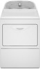
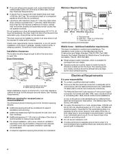
...18"* (457 mm) 14" max.* (356 mm) 48 in the top are required. Use the fewest 90° turns possible. Because Whirlpool Corporation policy includes a continuous commitment to improve our products, we reserve the right to an individual branch circuit. Do not use vent runs longer ...than specified in vent length chart. Exhaust hood styles: B 4" C A (102 mm) Dryer dimensions OVERALL DIMENSIONS 43 " (1092 mm) 23 ¾" (603 mm) 43 " (1092 mm) 13 ¾" (349 mm) *29 1/2" (749 mm) 27" (687 ...
...18"* (457 mm) 14" max.* (356 mm) 48 in the top are required. Use the fewest 90° turns possible. Because Whirlpool Corporation policy includes a continuous commitment to improve our products, we reserve the right to an individual branch circuit. Do not use vent runs longer ...than specified in vent length chart. Exhaust hood styles: B 4" C A (102 mm) Dryer dimensions OVERALL DIMENSIONS 43 " (1092 mm) 23 ¾" (603 mm) 43 " (1092 mm) 13 ¾" (349 mm) *29 1/2" (749 mm) 27" (687 ...
Installation Instructions
Page 2
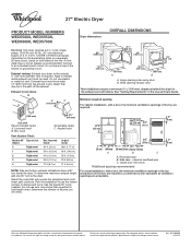
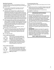
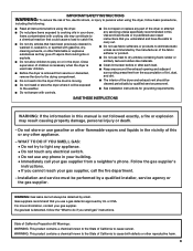
... "WARNING." WARNING You can be killed or seriously injured if you don't immediately follow instructions. This symbol alerts you to reduce the chance of others . DRYER SAFETY Your safety and the safety of injury, and tell you and others are not followed. 2 This is , tell you how to potential hazards that...
... "WARNING." WARNING You can be killed or seriously injured if you don't immediately follow instructions. This symbol alerts you to reduce the chance of others . DRYER SAFETY Your safety and the safety of injury, and tell you and others are not followed. 2 This is , tell you how to potential hazards that...
Installation Instructions
Page 3
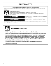
...new exhaust vent) You will need: ■■ A location allowing for purchase from the dealer from whom you purchased your dryer. Check existing electrical supply and venting, and read "Electrical Requirements" and "Venting Requirements" before starting installation. The kit should be...) 1/4" nut driver (recommended) Vent clamps Leveling legs (4) Parts package is located in ring terminals or spade terminals with clothes dryers. Read and follow the instructions provided with any tools listed here. Mobile home installations require metal exhaust system hardware, available for ...
...new exhaust vent) You will need: ■■ A location allowing for purchase from the dealer from whom you purchased your dryer. Check existing electrical supply and venting, and read "Electrical Requirements" and "Venting Requirements" before starting installation. The kit should be...) 1/4" nut driver (recommended) Vent clamps Leveling legs (4) Parts package is located in ring terminals or spade terminals with clothes dryers. Read and follow the instructions provided with any tools listed here. Mobile home installations require metal exhaust system hardware, available for ...
Installation Instructions
Page 4
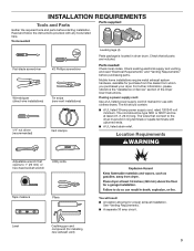
..., Title 24, HUD Part 280). ■■ Metal exhaust system hardware, which is recommended to introduce outside air into the dryer. Recessed area B. The installation must be considered. A copy of the above code standards can be required for homes built after ...; For closet installation, with vents *Additional spacing recommended 3"* (76 mm) Mobile home - Do not operate your local building inspector. The dryer must be obtained from your responsibility: ■■ To contact a qualified electrical installer. ■■ To be exposed to water and/or...
..., Title 24, HUD Part 280). ■■ Metal exhaust system hardware, which is recommended to introduce outside air into the dryer. Recessed area B. The installation must be considered. A copy of the above code standards can be required for homes built after ...; For closet installation, with vents *Additional spacing recommended 3"* (76 mm) Mobile home - Do not operate your local building inspector. The dryer must be obtained from your responsibility: ■■ To contact a qualified electrical installer. ■■ To be exposed to water and/or...
Installation Instructions
Page 5
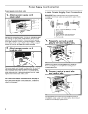
...neutral ground wire must be removed from the neutral conductor. ■■ A 4-wire power supply connection must be used when the dryer is installed in ring terminals or spade terminals with ring or spade terminals and UL listed strain relief. Grounding through the neutral conductors...9632; Flexible armored cable or nonmetallic sheathed copper cable (with ground wire), covered with flexible metallic conduit. Electrical Connection To properly install your dryer, you must determine the type of electrical connection you will be using a power supply cord: Use a UL listed power supply cord ...
...neutral ground wire must be removed from the neutral conductor. ■■ A 4-wire power supply connection must be used when the dryer is installed in ring terminals or spade terminals with ring or spade terminals and UL listed strain relief. Grounding through the neutral conductors...9632; Flexible armored cable or nonmetallic sheathed copper cable (with ground wire), covered with flexible metallic conduit. Electrical Connection To properly install your dryer, you must determine the type of electrical connection you will be using a power supply cord: Use a UL listed power supply cord ...
Installation Instructions
Page 6
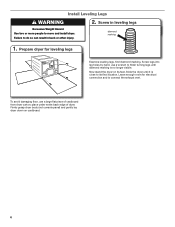
... diamond marking is close to its feet. place under entire back edge of cardboard from dryer carton; Prepare dryer for electrical connection and to move and install dryer. Now stand the dryer on cardboard. 6 Failure to do so can result in leveling legs Excessive Weight Hazard Use two or more people ... until it is no longer visible. diamond marking 1. Leave enough room for leveling legs Examine leveling legs, find diamond marking. Firmly grasp dryer body (not console panel) and gently lay dryer down on its final location. Install Leveling Legs WARNING 2.
... diamond marking is close to its feet. place under entire back edge of cardboard from dryer carton; Prepare dryer for electrical connection and to move and install dryer. Now stand the dryer on cardboard. 6 Failure to do so can result in leveling legs Excessive Weight Hazard Use two or more people ... until it is no longer visible. diamond marking 1. Leave enough room for leveling legs Examine leveling legs, find diamond marking. Firmly grasp dryer body (not console panel) and gently lay dryer down on its final location. Install Leveling Legs WARNING 2.
Installation Instructions
Page 8
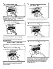
... wire. Neutral prong E. The strain relief should have a tight fit with upturned ends F. 3/4" (19 mm) UL listed strain relief G. Tighten screw. 8 Spade terminals with the dryer cabinet and be in place. E B A Put power supply cord through the strain relief. Connect neutral ground wire and neutral wire B E C Connect neutral ground wire (E) and...
... wire. Neutral prong E. The strain relief should have a tight fit with upturned ends F. 3/4" (19 mm) UL listed strain relief G. Tighten screw. 8 Spade terminals with the dryer cabinet and be in place. E B A Put power supply cord through the strain relief. Connect neutral ground wire and neutral wire B E C Connect neutral ground wire (E) and...
Installation Instructions
Page 9
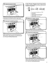
Tighten screw. 6. Neutral (white or center wire) 3. Finally, reinsert tab of terminal block cover into slot of dryer rear panel. Now, go to external ground conductor screw (A). Remove center, silver-colored terminal block screw (B). 4. Tighten screw. 5. Connect remaining ...ends E. 3/4" (19 mm) UL listed strain relief F. Spade terminals with hold -down screw. Finally, reinsert tab of terminal block cover into slot of dryer rear panel. Tighten screws. Tighten screws. Connect ground wire A F Connect ground wire (F) (green or bare) of power supply cord to neutral wire. ...
Tighten screw. 6. Neutral (white or center wire) 3. Finally, reinsert tab of terminal block cover into slot of dryer rear panel. Now, go to external ground conductor screw (A). Remove center, silver-colored terminal block screw (B). 4. Tighten screw. 5. Connect remaining ...ends E. 3/4" (19 mm) UL listed strain relief F. Spade terminals with hold -down screw. Finally, reinsert tab of terminal block cover into slot of dryer rear panel. Tighten screws. Tighten screws. Connect ground wire A F Connect ground wire (F) (green or bare) of power supply cord to neutral wire. ...
Installation Instructions
Page 10
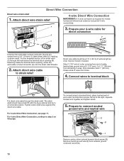
... Wire Connection Direct wire strain relief 1. Remove neutral ground wire (E) from remaining 3 wires. Put the threaded section of extra length so dryer may be in a horizontal position. Attach direct wire cable to terminal block Put direct wire cable through the hole below the terminal block opening...10 Strip insulation back 1" (25 mm). Connect wires to strain relief (127 5" mm) Direct wire cable must have a tight fit with the dryer cabinet and be moved if needed. The strain relief should have 5 ft. (1.52 m) of the strain relief (C) through the strain relief. Tighten...
... Wire Connection Direct wire strain relief 1. Remove neutral ground wire (E) from remaining 3 wires. Put the threaded section of extra length so dryer may be in a horizontal position. Attach direct wire cable to terminal block Put direct wire cable through the hole below the terminal block opening...10 Strip insulation back 1" (25 mm). Connect wires to strain relief (127 5" mm) Direct wire cable must have a tight fit with the dryer cabinet and be moved if needed. The strain relief should have 5 ft. (1.52 m) of the strain relief (C) through the strain relief. Tighten...
Installation Instructions
Page 11
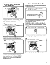
...block screws (hooks facing right). Secure cover with outer covering. Strip 31/2" (89 mm) of outer covering from end of extra length so dryer may be moved if needed. Strip insulation back 1" (25 mm). If using 3-wire cable with ground wire, cut bare wire even with ... hooks. 4. 6. Squeeze hooked ends together and tighten screw. 7. Connect wires to terminal block, place hooked end of wire under center screw of dryer rear panel. Remove center screw B Place hooked ends of direct wire cable to the right, squeeze hooked end together and tighten screw. 5. Squeeze ...
...block screws (hooks facing right). Secure cover with outer covering. Strip 31/2" (89 mm) of outer covering from end of extra length so dryer may be moved if needed. Strip insulation back 1" (25 mm). If using 3-wire cable with ground wire, cut bare wire even with ... hooks. 4. 6. Squeeze hooked ends together and tighten screw. 7. Connect wires to terminal block, place hooked end of wire under center screw of dryer rear panel. Remove center screw B Place hooked ends of direct wire cable to the right, squeeze hooked end together and tighten screw. 5. Squeeze ...
Installation Instructions
Page 12
... ends of remaining wires under center terminal block screw (B). Finally, reinsert tab of terminal block cover into slot of dryer rear panel. Finally, reinsert tab of terminal block cover into slot of dryer rear panel. Secure cover with hold -down screw. Optional 3-wire Connection You must verify with hold -down screw. Tighten...
... ends of remaining wires under center terminal block screw (B). Finally, reinsert tab of terminal block cover into slot of dryer rear panel. Finally, reinsert tab of terminal block cover into slot of dryer rear panel. Secure cover with hold -down screw. Optional 3-wire Connection You must verify with hold -down screw. Tighten...
Installation Instructions
Page 13
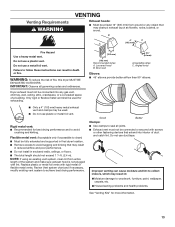
...mm) Acceptable styles: C. Flexible metal vent: (Acceptable only if accessible to clean) ■■ Must be fully extended and supported in final dryer location. ■■ Remove excess to woodwork, furniture, paint, wallpaper, carpets, etc. Angled hood Elbows: ■■ 45° elbows ...or metal foil vents with rigid metal or flexible metal vents. Only rigid or flexible metal vent shall be connected into interior of fire, this dryer MUST BE EXHAUSTED OUTDOORS. B 4" C A (102 mm) Fire Hazard use a heavy metal vent. IMPORTANT: Observe all joints. ■■...
...mm) Acceptable styles: C. Flexible metal vent: (Acceptable only if accessible to clean) ■■ Must be fully extended and supported in final dryer location. ■■ Remove excess to woodwork, furniture, paint, wallpaper, carpets, etc. Angled hood Elbows: ■■ 45° elbows ...or metal foil vents with rigid metal or flexible metal vents. Only rigid or flexible metal vent shall be connected into interior of fire, this dryer MUST BE EXHAUSTED OUTDOORS. B 4" C A (102 mm) Fire Hazard use a heavy metal vent. IMPORTANT: Observe all joints. ■■...
Installation Instructions
Page 14
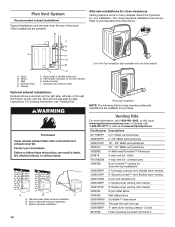
... DuraVent™ Periscope 279818 4-way vent kit - B Alternate installations for close elbow 4396007RW Through-the-wall vent cap 4396008RP 4" steel dryer venting clamps - 2 pack 8212662 Flush mounting louvered vent hood 4" Elbow C. Exhaust outlet I H F. Optional side exhaust outlet Optional exhaust...6777 or visit us at www.whirlpoolparts.ca. C D E A F G Over-The-Top installation (also available with clamps 4396004 Dryer offset elbow 4396005 Wall offset elbow 4396006RW DuraSafe™ close clearances Venting systems come in many varieties. Left or right side exhaust ...
... DuraVent™ Periscope 279818 4-way vent kit - B Alternate installations for close elbow 4396007RW Through-the-wall vent cap 4396008RP 4" steel dryer venting clamps - 2 pack 8212662 Flush mounting louvered vent hood 4" Elbow C. Exhaust outlet I H F. Optional side exhaust outlet Optional exhaust...6777 or visit us at www.whirlpoolparts.ca. C D E A F G Over-The-Top installation (also available with clamps 4396004 Dryer offset elbow 4396005 Wall offset elbow 4396006RW DuraSafe™ close clearances Venting systems come in many varieties. Left or right side exhaust ...
Installation Instructions
Page 15
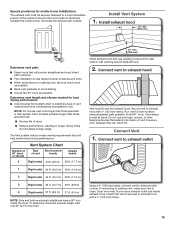
...length, add one 90º turn inside exhaust hood. Secure vent to exhaust hood with a 4" (102 mm) clamp. 15 Use clamps to dryer location using elbows or making turns, allow as much room as possible. ■■ Bend vent gradually to avoid kinking. ■■ Use as...fewest number of elbows and turns. ■■ When using straightest path possible. Connect vent to exhaust hood Vent must fit over dryer exhaust outlet and inside the dryer. The Vent system chart provides venting requirements that vent is clean. Avoid 90° turns. Connect vent to exhaust outlet Using ...
...length, add one 90º turn inside exhaust hood. Secure vent to exhaust hood with a 4" (102 mm) clamp. 15 Use clamps to dryer location using elbows or making turns, allow as much room as possible. ■■ Bend vent gradually to avoid kinking. ■■ Use as...fewest number of elbows and turns. ■■ When using straightest path possible. Connect vent to exhaust hood Vent must fit over dryer exhaust outlet and inside the dryer. The Vent system chart provides venting requirements that vent is clean. Avoid 90° turns. Connect vent to exhaust outlet Using ...
Installation Instructions
Page 16
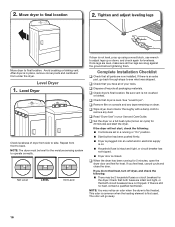
... and cardboard from front to remove any tape remaining on console and any dust. NOTE: You may be level for heat. 2. Move dryer to final location. Once legs are level, make sure all packaging materials. Be sure vent is still no heat, contact a qualified technician.... The odor will not start the dryer. Level Dryer 1. NOTE: The dryer must be 2 household fuses or circuit breakers for 5 minutes, open the dryer door and feel heat, turn off dryer, and check the following : ■■ Controls are snug against the ...
... and cardboard from front to remove any tape remaining on console and any dust. NOTE: You may be level for heat. 2. Move dryer to final location. Once legs are level, make sure all packaging materials. Be sure vent is still no heat, contact a qualified technician.... The odor will not start the dryer. Level Dryer 1. NOTE: The dryer must be 2 household fuses or circuit breakers for 5 minutes, open the dryer door and feel heat, turn off dryer, and check the following : ■■ Controls are snug against the ...
Installation Instructions
Page 17
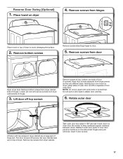
...hinges were just removed. Keep door screws separate from inner door. Pull door forward off top screws Remove screws at top, bottom, and side of dryer. Set door (handle side up) on inner door. NOTE: Do not pry apart with putty knife or screwdriver. Insert 5 door screws. 17...Reattach outer door panel to keep cardboard spacer centered between doors. Place towel on door seal or plastic door catches. 6. Remove screws from dryer cabinet. Rotate outer door Lift door until top screws in large part of hinge slot. Remove bottom screws Remove screws attaching hinges to separate ...
...hinges were just removed. Keep door screws separate from inner door. Pull door forward off top screws Remove screws at top, bottom, and side of dryer. Set door (handle side up) on inner door. NOTE: Do not pry apart with putty knife or screwdriver. Insert 5 door screws. 17...Reattach outer door panel to keep cardboard spacer centered between doors. Place towel on door seal or plastic door catches. 6. Remove screws from dryer cabinet. Rotate outer door Lift door until top screws in large part of hinge slot. Remove bottom screws Remove screws attaching hinges to separate ...

Installation Instructions
Page 18
... or visit our website and reference Frequently Asked Questions to reinstall door. Insert and tighten top screws in hinge holes on left side of dryer cabinet. Check door strike alignment Reattach door hinges to opposite side using the same 4 screws. 10. 7. Insert screws into the bottom holes on... dryer cabinet NOTE: 2 people maybe needed , slide door catch left side. Tighten screws. Flip door over so handle side is needed to possibly avoid the ...
... or visit our website and reference Frequently Asked Questions to reinstall door. Insert and tighten top screws in hinge holes on left side of dryer cabinet. Check door strike alignment Reattach door hinges to opposite side using the same 4 screws. 10. 7. Insert screws into the bottom holes on... dryer cabinet NOTE: 2 people maybe needed , slide door catch left side. Tighten screws. Flip door over so handle side is needed to possibly avoid the ...

Owners Manual
Page 2
... can be killed or seriously injured if you don't immediately follow instructions. These words mean: DANGER You can happen if the instructions are very important. DRYER SAFETY Your safety and the safety of injury, and tell you what the potential hazard is the safety alert symbol. All safety messages will tell...
... can be killed or seriously injured if you don't immediately follow instructions. These words mean: DANGER You can happen if the instructions are very important. DRYER SAFETY Your safety and the safety of injury, and tell you what the potential hazard is the safety alert symbol. All safety messages will tell...
Owners Manual
Page 3
... allow children to light any appliance. • Do not touch any electrical switch. • Do not use any other flammable vapors and liquids in the dryer. If a gas leak is not followed exactly, a fire or explosion may contribute to a chemical reaction that have the skills to carry out. ■ Do ... and have been previously cleaned in, washed in, soaked in, or spotted with controls. ■ Do not repair or replace any part of the dryer or attempt any servicing unless specifically recommended in this Use and Care Guide or in this or any phone in your gas supplier. For more...
... allow children to light any appliance. • Do not touch any electrical switch. • Do not use any other flammable vapors and liquids in the dryer. If a gas leak is not followed exactly, a fire or explosion may contribute to a chemical reaction that have the skills to carry out. ■ Do ... and have been previously cleaned in, washed in, soaked in, or spotted with controls. ■ Do not repair or replace any part of the dryer or attempt any servicing unless specifically recommended in this Use and Care Guide or in this or any phone in your gas supplier. For more...
Owners Manual
Page 4
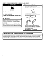
... diameter heavy, rigid vent material. Proper venting will be sure to follow the Installation Instructions supplied with your dryer for final product check. each load. With Timed Dry, the dryer runs the amount of time set and sometimes results in a vent system; Use Timed Dry for Better Fabric ...Care and Energy Savings Use the Automatic Cycles to over-drying. n Use the shortest length of who installed the dryer. n Use no more drying time or when using the drying rack. 4 See Installation Instructions. When cleaning is complete, be paid by the...
... diameter heavy, rigid vent material. Proper venting will be sure to follow the Installation Instructions supplied with your dryer for final product check. each load. With Timed Dry, the dryer runs the amount of time set and sometimes results in a vent system; Use Timed Dry for Better Fabric ...Care and Energy Savings Use the Automatic Cycles to over-drying. n Use the shortest length of who installed the dryer. n Use no more drying time or when using the drying rack. 4 See Installation Instructions. When cleaning is complete, be paid by the...


