
Uk Manual
Page 1
... and instructions in the space above for future reference. If you have questions, or if there are committed to providing complete customer satisfaction. Write the serial number in this manual before using this manual for reference. Serial Number Decal (under seat) QUESTIONS? Model No.WLEVSY98110 Serial No. As a manufacturer, we are missing or damaged parts, please call: 08457 089 009 Or write: ICON Health & Fitness, Ltd...
... and instructions in the space above for future reference. If you have questions, or if there are committed to providing complete customer satisfaction. Write the serial number in this manual before using this manual for reference. Serial Number Decal (under seat) QUESTIONS? Model No.WLEVSY98110 Serial No. As a manufacturer, we are missing or damaged parts, please call: 08457 089 009 Or write: ICON Health & Fitness, Ltd...
Uk Manual
Page 2
Remove the PART IDENTIFICATION CHART before beginning assembly. TABLE OF CONTENTS IMPORTANT PRECAUTIONS 3 BEFORE YOU BEGIN 4 ASSEMBLY 5 ADJUSTMENT 15 WEIGHT RESISTANCE CHART 17 TROUBLESHOOTING AND MAINTENANCE 18 CABLE DIAGRAM 19 PART LIST 22 EXPLODED DRAWING 23 ORDERING REPLACEMENT PARTS Back Cover Note: A PART IDENTIFICATION CHART is a registered trademark of this manual. WESLO is attached in the centre of ICON Health & Fitness, Inc. 2
Remove the PART IDENTIFICATION CHART before beginning assembly. TABLE OF CONTENTS IMPORTANT PRECAUTIONS 3 BEFORE YOU BEGIN 4 ASSEMBLY 5 ADJUSTMENT 15 WEIGHT RESISTANCE CHART 17 TROUBLESHOOTING AND MAINTENANCE 18 CABLE DIAGRAM 19 PART LIST 22 EXPLODED DRAWING 23 ORDERING REPLACEMENT PARTS Back Cover Note: A PART IDENTIFICATION CHART is a registered trademark of this manual. WESLO is attached in the centre of ICON Health & Fitness, Inc. 2
Uk Manual
Page 3
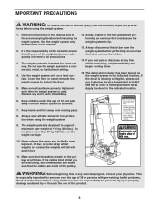
... (125 lbs.) on a level surface. Never release the press arm, butterfly arms, leg lever, lat bar, or nylon strap whilst weights are exercising, stop immediately and begin cooling down. 15. Apply the decal in the indicated location. Make sure all parts are adequately informed of all users of 12 and pets away from moving parts. 8. The weight system is used. If you are raised; IMPORTANT PRECAUTIONS WARNING: To...
... (125 lbs.) on a level surface. Never release the press arm, butterfly arms, leg lever, lat bar, or nylon strap whilst weights are exercising, stop immediately and begin cooling down. 15. Apply the decal in the indicated location. Make sure all parts are adequately informed of all users of 12 and pets away from moving parts. 8. The weight system is used. If you are raised; IMPORTANT PRECAUTIONS WARNING: To...
Uk Manual
Page 4
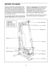
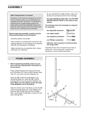
... achieve the specific results you want. For your benefit, read this manual carefully before calling. If you have questions after reading this owner's manual for selecting the versatile WESLO® GYM 1000 weight system. Before reading further, please familiarise yourself with the parts that are labelled in .) High Pulley Station Lat Bar Butterfly Arms Backrest Seat Weight Carriage Press Arm Leg Lever Low Pulley Station Foot Plate 4 ASSEMBLED DIMENSIONS: Height: 193...
... achieve the specific results you want. For your benefit, read this manual carefully before calling. If you have questions after reading this owner's manual for selecting the versatile WESLO® GYM 1000 weight system. Before reading further, please familiarise yourself with the parts that are labelled in .) High Pulley Station Lat Bar Butterfly Arms Backrest Seat Weight Carriage Press Arm Leg Lever Low Pulley Station Foot Plate 4 ASSEMBLED DIMENSIONS: Height: 193...
Uk Manual
Page 5
... • lubricant, such as you assemble them, unless instructed to ensure that the weight system can be more convenient if you have a socket set, a set of open-end or closed-end wrenches, or a set of ratchet wrenches. Before beginning assembly, make sure all parts are oriented as shown in the drawings. • For help identifying small parts, use the PART IDENTIFICATION CHART in the...
... • lubricant, such as you assemble them, unless instructed to ensure that the weight system can be more convenient if you have a socket set, a set of open-end or closed-end wrenches, or a set of ratchet wrenches. Before beginning assembly, make sure all parts are oriented as shown in the drawings. • For help identifying small parts, use the PART IDENTIFICATION CHART in the...
Uk Manual
Page 6
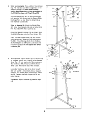
... the Rear Upright (56). 2. Press a 25mm Round Inner Cap (49) into the top of the weight tube on top. Attach the Weight Stop (67) to the Front Upright (42) with an M8 x 70mm Bolt (11) and an M8 Nylon Locknut (3). Slide the Front Upright onto the M8 x 63mm Carriage Bolts (1) in steps 1-3. 3 27 8 72 72 55 8 49 44 3 44 Crossbar 56 3 42 6 Tighten...
... the Rear Upright (56). 2. Press a 25mm Round Inner Cap (49) into the top of the weight tube on top. Attach the Weight Stop (67) to the Front Upright (42) with an M8 x 70mm Bolt (11) and an M8 Nylon Locknut (3). Slide the Front Upright onto the M8 x 63mm Carriage Bolts (1) in steps 1-3. 3 27 8 72 72 55 8 49 44 3 44 Crossbar 56 3 42 6 Tighten...
Uk Manual
Page 7
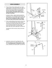
... two M8 Nylon Locknuts (3). the Plastic Bushings should fit over the ends of the handle on the Press Frame (17). Lubricate an M10 x 198mm Bolt (59). ARM ASSEMBLY 4 4. Note: Do not overtighten the Nylon Locknut; Attach the Press Frame (17) to the Base (4) with the indicated tube in the base. Press a 25mm Round Inner Cap (49) into each end...
... two M8 Nylon Locknuts (3). the Plastic Bushings should fit over the ends of the handle on the Press Frame (17). Lubricate an M10 x 198mm Bolt (59). ARM ASSEMBLY 4 4. Note: Do not overtighten the Nylon Locknut; Attach the Press Frame (17) to the Base (4) with the indicated tube in the base. Press a 25mm Round Inner Cap (49) into each end...
Uk Manual
Page 8
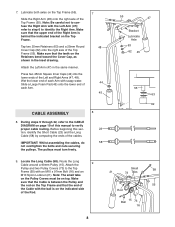
... page 19 of each Arm. 7 48 44 45 CABLE ASSEMBLY 8. Wet the lower end of this section, identify the Short Cable (23) and the Long Cable (58) by comparing the ends of the Top Frame (55). Before beginning this manual to verify proper cable routing. The pulleys must be on top. Attach the 9 Pulley and two Pulley Covers (73) to the CABLE DIAGRAM on the Retainers...
... page 19 of each Arm. 7 48 44 45 CABLE ASSEMBLY 8. Wet the lower end of this section, identify the Short Cable (23) and the Long Cable (58) by comparing the ends of the Top Frame (55). Before beginning this manual to verify proper cable routing. The pulleys must be on top. Attach the 9 Pulley and two Pulley Covers (73) to the CABLE DIAGRAM on the Retainers...
Uk Manual
Page 9
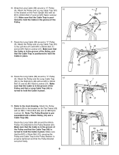
... of the Pulley. 11. assembled with an M10 x 60mm Bolt (7) and an M10 Nylon Locknut (21). Make sure that the Cable Trap is pre- Make sure that the Cable is turned to hold the Cable in place. Note: The Pulley Bracket is posi- Attach the Pulley and a Long Cable Trap (50) 10 to the Pulley Bracket (20). Route the Long Cable (58) around a "V"-Pulley (6). tioned...
... of the Pulley. 11. assembled with an M10 x 60mm Bolt (7) and an M10 Nylon Locknut (21). Make sure that the Cable Trap is pre- Make sure that the Cable is turned to hold the Cable in place. Note: The Pulley Bracket is posi- Attach the Pulley and a Long Cable Trap (50) 10 to the Pulley Bracket (20). Route the Long Cable (58) around a "V"-Pulley (6). tioned...
Uk Manual
Page 11
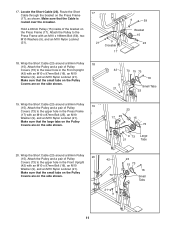
... (21). Attach the Pulley and a pair of Pulley Covers (73) to the Press Frame with an M10 x 97mm Bolt (16), an M10 Washer (9), and an M10 Nylon Locknut (21). 17. Locate the Short Cable (23). Wrap the Short Cable (23) around a 90mm Pulley (15). Make sure that the Cable is routed over the crossbar. Attach the Pulley to the lower hole in the Press Frame (17...
... (21). Attach the Pulley and a pair of Pulley Covers (73) to the Press Frame with an M10 x 97mm Bolt (16), an M10 Washer (9), and an M10 Nylon Locknut (21). 17. Locate the Short Cable (23). Wrap the Short Cable (23) around a 90mm Pulley (15). Make sure that the Cable is routed over the crossbar. Attach the Pulley to the lower hole in the Press Frame (17...
Uk Manual
Page 12
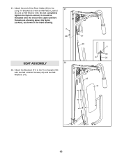
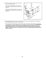
Do not completely tighten the Nylon Locknut; 21. it should be threaded onto the end of the Short Cable (23) to the Front Upright (42) with an M8 Nylon Locknut (3) and an M8 Washer (68). Attach the Backrest (41) to the 21 Long "U"-Bracket (57) with two M6 x 63mm Screws (43) and two M6 Washers (10). 57 23 3 68 57 23 42 41 43 10 12 Attach the end of the Cable until two threads are showing above the Nylon Locknut, as shown in the inset drawing. 3 68 SEAT ASSEMBLY 22 22.
Do not completely tighten the Nylon Locknut; 21. it should be threaded onto the end of the Short Cable (23) to the Front Upright (42) with an M8 Nylon Locknut (3) and an M8 Washer (68). Attach the Backrest (41) to the 21 Long "U"-Bracket (57) with two M6 x 63mm Screws (43) and two M6 Washers (10). 57 23 3 68 57 23 42 41 43 10 12 Attach the end of the Cable until two threads are showing above the Nylon Locknut, as shown in the inset drawing. 3 68 SEAT ASSEMBLY 22 22.
Uk Manual
Page 13
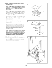
... M6 x 16mm Screws (18). the Leg Lever must pivot freely. Note: Make sure the Eyebolt is positioned vertically on the indicated pin in the Seat Frame (36). Attach the Seat Plate to the Front Upright with the Bolt and an M8 Nylon Locknut (3). Attach the Seat Frame to the Seat (13) with an M6 Washer (10) onto the Carriage Bolt. Press a 38mm Square...
... M6 x 16mm Screws (18). the Leg Lever must pivot freely. Note: Make sure the Eyebolt is positioned vertically on the indicated pin in the Seat Frame (36). Attach the Seat Plate to the Front Upright with the Bolt and an M8 Nylon Locknut (3). Attach the Seat Frame to the Seat (13) with an M6 Washer (10) onto the Carriage Bolt. Press a 38mm Square...
Uk Manual
Page 14
... parts have been properly tightened. If there is used. See the CABLE DIAGRAM on page 19 of the cables does not move smoothly over the pulleys. Make sure that the cables move smoothly, find and correct the problem. If one Pad Tube (28) into the Seat Frame (36). IMPORTANT: If the cables are not properly routed, they may be explained in the cables, you will need...
... parts have been properly tightened. If there is used. See the CABLE DIAGRAM on page 19 of the cables does not move smoothly over the pulleys. Make sure that the cables move smoothly, find and correct the problem. If one Pad Tube (28) into the Seat Frame (36). IMPORTANT: If the cables are not properly routed, they may be explained in the cables, you will need...
Uk Manual
Page 15
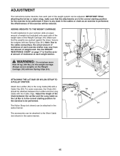
... 19 Weight Tube the amount of weight used. Always secure weights on the Weight Carriage (19). IMPORTANT: When attaching the lat bar or nylon strap, make sure that the weights are in the correct starting position for the exercise to be performed. Secure the weights with two Cable Clips. Use the WEIGHT RESISTANCE CHART on the weight carriage. Adjust the length of the Chain between the Lat Bar and the Long Cable with...
... 19 Weight Tube the amount of weight used. Always secure weights on the Weight Carriage (19). IMPORTANT: When attaching the lat bar or nylon strap, make sure that the weights are in the correct starting position for the exercise to be performed. Secure the weights with two Cable Clips. Use the WEIGHT RESISTANCE CHART on the weight carriage. Adjust the length of the Chain between the Lat Bar and the Long Cable with...
Uk Manual
Page 16
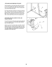
... THE LOW PULLEY STATION To use the Leg Lever (29), the seat must be attached to the front upright (see ATTACHING AND REMOVING THE SEAT above). For some exercises, the Seat (13) must be removed. Next, remove the Seat Knob (40) and the M8 x 67mm Carriage Bolt (14) from the Seat Frame (36). Attach one end of the Chain to the M10 x 63mm Eyebolt (35) with a Cable Clip. Attach the...
... THE LOW PULLEY STATION To use the Leg Lever (29), the seat must be attached to the front upright (see ATTACHING AND REMOVING THE SEAT above). For some exercises, the Seat (13) must be removed. Next, remove the Seat Knob (40) and the M8 x 67mm Carriage Bolt (14) from the Seat Frame (36). Attach one end of the Chain to the M10 x 63mm Eyebolt (35) with a Cable Clip. Attach the...
Uk Manual
Page 17
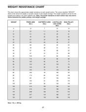
...resistance at each station may vary due to the amount of weight, in pounds, placed on the weight carriage. The column labelled "WEIGHT" refers to friction between the cables, pulleys, and weight carriage. WEIGHT 0 5 10 15 20 25 30 35 40 45 50 55 60 65 70 75 80 85 90 95 100 105 110 115 120 125 PRESS ARM... 116 100 160 121 104 168 126 109 175 131 113 182 137 118 189 142 Note: 1 lb. = .454 kg 17 WEIGHT RESISTANCE CHART This chart shows the approximate weight resistance at each weight station. The weight resistance shown for the butterfly arm station is for each butterfly...
...resistance at each station may vary due to the amount of weight, in pounds, placed on the weight carriage. The column labelled "WEIGHT" refers to friction between the cables, pulleys, and weight carriage. WEIGHT 0 5 10 15 20 25 30 35 40 45 50 55 60 65 70 75 80 85 90 95 100 105 110 115 120 125 PRESS ARM... 116 100 160 121 104 168 126 109 175 131 113 182 137 118 189 142 Note: 1 lb. = .454 kg 17 WEIGHT RESISTANCE CHART This chart shows the approximate weight resistance at each weight station. The weight resistance shown for the butterfly arm station is for each butterfly...
Uk Manual
Page 18
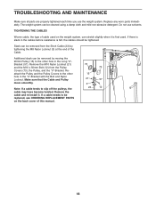
... moving the 90mm Pulley (15) to be replaced, see ORDERING REPLACEMENT PARTS on the weight system, can be tightened. Reattach the Pulley and the Pulley Covers to slip off the pulleys, the cable may have become twisted. Note: If a cable tends to the other hole in the cables before resistance is first used on the back cover of the Cable. Replace any worn parts immediately. TROUBLESHOOTING AND MAINTENANCE Make sure all parts are properly tightened...
... moving the 90mm Pulley (15) to be replaced, see ORDERING REPLACEMENT PARTS on the weight system, can be tightened. Reattach the Pulley and the Pulley Covers to slip off the pulleys, the cable may have become twisted. Note: If a cable tends to the other hole in the cables before resistance is first used on the back cover of the Cable. Replace any worn parts immediately. TROUBLESHOOTING AND MAINTENANCE Make sure all parts are properly tightened...

Uk Manual
Page 19
... correct position of each cable. The starting and ending points of the Short Cable (23) and the Long Cable (58). CABLE DIAGRAM The cable diagram below shows the proper routing of each cable are labelled. Use the diagram to make sure that the cable traps do not touch or bind the cables. 2 7 5 1-High Pulley 3 4 Long Cable (58) TOP VIEW 6 5-Long "U"-Bracket Short Cable (23) Weight Carriage-8 4 3 1-Low Pulley 2 19
... correct position of each cable. The starting and ending points of the Short Cable (23) and the Long Cable (58). CABLE DIAGRAM The cable diagram below shows the proper routing of each cable are labelled. Use the diagram to make sure that the cable traps do not touch or bind the cables. 2 7 5 1-High Pulley 3 4 Long Cable (58) TOP VIEW 6 5-Long "U"-Bracket Short Cable (23) Weight Carriage-8 4 3 1-Low Pulley 2 19

Uk Manual
Page 22
... x 50mm Carriage Bolt 39 1 Nylon Strap 40 1 Seat Knob 41 1 Backrest 42 1 Front Upright 43 2 M6 x 63mm Screw 44 6 45mm Square Inner Cap 45 2 Large Foam Pad 46 2 Press Arm 47 1 Left Arm 48 1 Right Arm 49 8 25mm Round Inner Cap 50 3 Long Cable Trap 51 2 50mm Square Outer Cap 52 1 Chain 53 2 Cable Clip 54 1 Lat Bar 55 1 Top Frame 56 1 Rear Upright 57 1 Long...
... x 50mm Carriage Bolt 39 1 Nylon Strap 40 1 Seat Knob 41 1 Backrest 42 1 Front Upright 43 2 M6 x 63mm Screw 44 6 45mm Square Inner Cap 45 2 Large Foam Pad 46 2 Press Arm 47 1 Left Arm 48 1 Right Arm 49 8 25mm Round Inner Cap 50 3 Long Cable Trap 51 2 50mm Square Outer Cap 52 1 Chain 53 2 Cable Clip 54 1 Lat Bar 55 1 Top Frame 56 1 Rear Upright 57 1 Long...
Uk Manual
Page 27
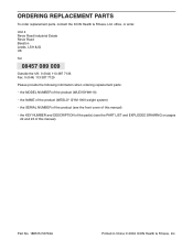
... information when ordering replacement parts: • the MODEL NUMBER of the product (WLEVSY98110) • the NAME of the product (WESLO® GYM 1000 weight system) • the SERIAL NUMBER of the product (see the front cover of this manual) • the KEY NUMBER and DESCRIPTION of the part(s) (see the PART LIST and EXPLODED DRAWING on pages 22 and 23 of this manual). ORDERING REPLACEMENT PARTS To order replacement parts, contact the ICON Health & Fitness, Ltd. Part...
... information when ordering replacement parts: • the MODEL NUMBER of the product (WLEVSY98110) • the NAME of the product (WESLO® GYM 1000 weight system) • the SERIAL NUMBER of the product (see the front cover of this manual) • the KEY NUMBER and DESCRIPTION of the part(s) (see the PART LIST and EXPLODED DRAWING on pages 22 and 23 of this manual). ORDERING REPLACEMENT PARTS To order replacement parts, contact the ICON Health & Fitness, Ltd. Part...


