
English Manual
Page 1
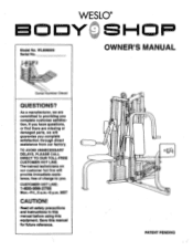
PATENT PENDING As a manufacturer, we will provide immediate assistance, free of charge to providing you complete satisfaction through direct assistance from our factory. MST CAUTION! Read all safety precautions and instructions in this manual before using this manual for future reference. WESLO® SHOP OWNER'S MANUAL Serial Number Decal QUESTIONS? The trained technicians on our customer hot line will guarantee you complete customer satisfaction...
PATENT PENDING As a manufacturer, we will provide immediate assistance, free of charge to providing you complete satisfaction through direct assistance from our factory. MST CAUTION! Read all safety precautions and instructions in this manual before using this manual for future reference. WESLO® SHOP OWNER'S MANUAL Serial Number Decal QUESTIONS? The trained technicians on our customer hot line will guarantee you complete customer satisfaction...
English Manual
Page 2
... cross training system. Read all Instructions before using the cross training system. 1. Always wear athletic shoes for hydraulic cylinders. 9. WESLO assumes no responsibility for protection. Cover the floor beneath the stepper for personal injury or 2 property damage sustained by or through the use the cross training system. TABLE OF CONTENTS IMPORTANT SAFETY PRECAUTIONS BEFORE YOU BEGIN ASSEMBLY ADJUSTING THE CROSS TRAINING SYSTEM TROUBLE-SHOOTING AND MAINTENANCE ORDERING REPLACEMENT PARTS LIMITED WARRANTY...
... cross training system. Read all Instructions before using the cross training system. 1. Always wear athletic shoes for hydraulic cylinders. 9. WESLO assumes no responsibility for protection. Cover the floor beneath the stepper for personal injury or 2 property damage sustained by or through the use the cross training system. TABLE OF CONTENTS IMPORTANT SAFETY PRECAUTIONS BEFORE YOU BEGIN ASSEMBLY ADJUSTING THE CROSS TRAINING SYSTEM TROUBLE-SHOOTING AND MAINTENANCE ORDERING REPLACEMENT PARTS LIMITED WARRANTY...
English Manual
Page 3
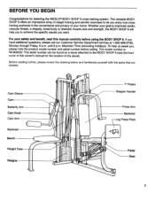
... product model number and serial number before using the BODY SHOP 9. Before reading further, please review the drawing below and familiarize yourself with the parts that are labeled. Whether your safety and benefit, read this owner's manual for selecting the WESLO® BODY SHOP 9 cross training system. Mountain Time (excluding holidays). Cam Sleeve Cam Butterfly Arm Cam Knob Cam Arm Backrest Bench Weight Tube J J Weights "I" Plates Stepper Handle Press Arm Backrest Leg Press Plate ..mg$11 Pedal Seat...
... product model number and serial number before using the BODY SHOP 9. Before reading further, please review the drawing below and familiarize yourself with the parts that are labeled. Whether your safety and benefit, read this owner's manual for selecting the WESLO® BODY SHOP 9 cross training system. Mountain Time (excluding holidays). Cam Sleeve Cam Butterfly Arm Cam Knob Cam Arm Backrest Bench Weight Tube J J Weights "I" Plates Stepper Handle Press Arm Backrest Leg Press Plate ..mg$11 Pedal Seat...
English Manual
Page 4
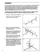
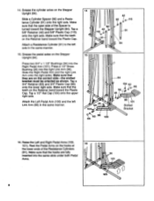
....) Attach the Press Upright with two 5/16" x 2 3/4" Bolts (12) and 5/16" Nylock Nuts (1). 3. The following tools (not Included) are also needed. 1. The Press Upright can be used in assembly. Remove all parts of the cross training system in the location where it will be identified by the sets of the packing materials until assembly is similar to the PART IDENTIFICATION CHART accompanying this owner's manual for help identifying the small parts used . Grease...
....) Attach the Press Upright with two 5/16" x 2 3/4" Bolts (12) and 5/16" Nylock Nuts (1). 3. The following tools (not Included) are also needed. 1. The Press Upright can be used in assembly. Remove all parts of the cross training system in the location where it will be identified by the sets of the packing materials until assembly is similar to the PART IDENTIFICATION CHART accompanying this owner's manual for help identifying the small parts used . Grease...

English Manual
Page 7
..., make sure that the Cable is pointed in the Stepper Upright. Align the hole in the Stepper Handle with a 5/16" x 2 1/2" Bolt (9), a 5/16" Washer (4), the 1/2" x 9/16" Bushing (21), another 5/16" Washer (4) and a 5/16" Nylock Nut (1). Attach two of the Weight Guides (80) to the Stepper Upright (84) with soapy water. Tighten all Nylock Nuts used In assembly steps 2 through 10 the Stepper...
..., make sure that the Cable is pointed in the Stepper Upright. Align the hole in the Stepper Handle with a 5/16" x 2 1/2" Bolt (9), a 5/16" Washer (4), the 1/2" x 9/16" Bushing (21), another 5/16" Washer (4) and a 5/16" Nylock Nut (1). Attach two of the Weight Guides (80) to the Stepper Upright (84) with soapy water. Tighten all Nylock Nuts used In assembly steps 2 through 10 the Stepper...
English Manual
Page 8
... on the hooks at the lower ends of the Spacer is turned toward the Stepper Upright (84). Tap a 3/4" Retainer (63) and 3/4" Plastic Cap (66) onto the lower right axle. Slide the Right Pedal Arm and the right Link Arm onto the right axles. Make sure that the open side of the Resistance Cylinders (91). Grease the cylinder axles on the...
... on the hooks at the lower ends of the Spacer is turned toward the Stepper Upright (84). Tap a 3/4" Retainer (63) and 3/4" Plastic Cap (66) onto the lower right axle. Slide the Right Pedal Arm and the right Link Arm onto the right axles. Make sure that the open side of the Resistance Cylinders (91). Grease the cylinder axles on the...
English Manual
Page 9
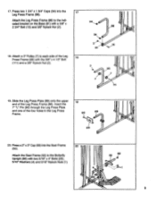
...; 111 19. Attach a 3" Pulley (7) to the Butterfly Upright (86) with two 5/16" x 4" Bolts (25), 5/16" Washers (4) and 5/16" Nylock Nuts (1). 20 : V8 2 . 52 i59 1 9 Press a 2" x 3" Cap (59) into the 17 Leg Press Frame (88). Insert the 7" "L" Pin (90) through the Leg Press Plate and one of the Leg Press Frame (88). Attach the Seat Frame (52) to each side of the Leg 18 I Press Frame (88...
...; 111 19. Attach a 3" Pulley (7) to the Butterfly Upright (86) with two 5/16" x 4" Bolts (25), 5/16" Washers (4) and 5/16" Nylock Nuts (1). 20 : V8 2 . 52 i59 1 9 Press a 2" x 3" Cap (59) into the 17 Leg Press Frame (88). Insert the 7" "L" Pin (90) through the Leg Press Plate and one of the Leg Press Frame (88). Attach the Seat Frame (52) to each side of the Leg 18 I Press Frame (88...
English Manual
Page 10
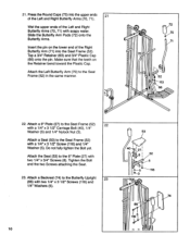
.... Attach a Seat (53) to the Seat Frame (52) 22 with a 1/4" x 3 1/2" Carriage Bolt (40), 1/4" Washer (5) and 1/4" Nylock Nut (3). Slide the Butterfly Arm Pads (72) onto the Butterfly Arms. Insert the pin on the Retainer bend toward the Plastic Cap. Do not fully tighten the Bolt yet. Tighten the Bolt and the two Screws attaching the Seat. 23. Attach a 6" Plate (27) to the Seat Frame (52) with two 1/4" x 3/4" Screws (8). Attach...
.... Attach a Seat (53) to the Seat Frame (52) 22 with a 1/4" x 3 1/2" Carriage Bolt (40), 1/4" Washer (5) and 1/4" Nylock Nut (3). Slide the Butterfly Arm Pads (72) onto the Butterfly Arms. Insert the pin on the Retainer bend toward the Plastic Cap. Do not fully tighten the Bolt yet. Tighten the Bolt and the two Screws attaching the Seat. 23. Attach a 6" Plate (27) to the Seat Frame (52) with two 1/4" x 3/4" Screws (8). Attach...
English Manual
Page 12
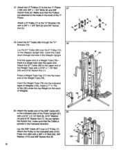
... the indicated direction. Lay the 258" Cable (97) over the 6" Pulley (10) on the stack of the Press Arm (60) with a 3/8" x 4" Bolt (33), 3/8" Washer (110) and 3/8" Nylock Nut (2). 29 87 1 4 97 2 110'°. 9 60 133 12 Press a Weight Tube Cap (77) into the indicated stack of the Weight Tube with a 3/8" x 1 3/4" Bolt (6) and 3/8" Nylock Nut (2). 27 6 7 7 2 6 2 108 19 28. Attach the Pulley to...
... the indicated direction. Lay the 258" Cable (97) over the 6" Pulley (10) on the stack of the Press Arm (60) with a 3/8" x 4" Bolt (33), 3/8" Washer (110) and 3/8" Nylock Nut (2). 29 87 1 4 97 2 110'°. 9 60 133 12 Press a Weight Tube Cap (77) into the indicated stack of the Weight Tube with a 3/8" x 1 3/4" Bolt (6) and 3/8" Nylock Nut (2). 27 6 7 7 2 6 2 108 19 28. Attach the Pulley to...
English Manual
Page 13
... 258" Cable (97) over the Pulley. Tighten a 3/8" Nylock Nut (2) with the 3/8" x 2" Bolt (109) and a 3/8" Nylock Nut (2). Insert the Bolt from the indicated side through the Press Upright (87). Route the 258" Cable (97) 33 under a 3" Pulley 32 (7). Attach the Pulley to the indicated bracket on the Leg Press Frame (88). 97 88 32. Route the 258" Cable (97) up around the 87 indicated 3" Pulley (7) on the Leg Press Frame...
... 258" Cable (97) over the Pulley. Tighten a 3/8" Nylock Nut (2) with the 3/8" x 2" Bolt (109) and a 3/8" Nylock Nut (2). Insert the Bolt from the indicated side through the Press Upright (87). Route the 258" Cable (97) 33 under a 3" Pulley 32 (7). Attach the Pulley to the indicated bracket on the Leg Press Frame (88). 97 88 32. Route the 258" Cable (97) up around the 87 indicated 3" Pulley (7) on the Leg Press Frame...
English Manual
Page 14
... turned as shown. Tighten a 3/8" Nylock Nut (2) onto the Bolt. As you tighten the Nylock Nut, make sure that the "I " 35 Plates (108). Insert the Cable down through the Cam Upright (85). Attach one end of the 195" Cable (98) to the bracket on the Cam Upright (85). Lay the 195" Cable (98) over the Pulley. Lay the 195" Cable (98) over a 3" Pulley (7). Attach the Pulley...
... turned as shown. Tighten a 3/8" Nylock Nut (2) onto the Bolt. As you tighten the Nylock Nut, make sure that the "I " 35 Plates (108). Insert the Cable down through the Cam Upright (85). Attach one end of the 195" Cable (98) to the bracket on the Cam Upright (85). Lay the 195" Cable (98) over the Pulley. Lay the 195" Cable (98) over a 3" Pulley (7). Attach the Pulley...
English Manual
Page 15
... the Pulley and the Cable Trap. Do not overtighten the Nylock Nut; Attach one end of the 108" Cable (73) to the 38 Right Butterfly Arm (71) with a 5/16" x 1 1/2" Bolt (54) and 5/16" Nylock Nut (1). Insert the 108" Cable (73) through the bracket on the Butterfly Upright (86) in the same manner. 70 -0 1 71 73 55 15 Press a Weight Tube...
... the Pulley and the Cable Trap. Do not overtighten the Nylock Nut; Attach one end of the 108" Cable (73) to the 38 Right Butterfly Arm (71) with a 5/16" x 1 1/2" Bolt (54) and 5/16" Nylock Nut (1). Insert the 108" Cable (73) through the bracket on the Butterfly Upright (86) in the same manner. 70 -0 1 71 73 55 15 Press a Weight Tube...

English Manual
Page 16
Tighten the Bolt and the two Screws attaching the Seat. 39. Wet the handles on the Press Upright (87). Do not fully tighten the Bolt yet. Turn the Cam Sleeve (44) as shown with two 1/4" x 3 1/2" Screws (116) and 1/4" Washers (5). 39 74 1 116 -87 40. Attach 42 the Cam Roller (37) to the Seat Bracket (20) with a 1/4" x 2 1/2" Carriage Bolt (106), 1/4" Washer (5) and 1/4" Nylock Nut (3). 106 22 27...
Tighten the Bolt and the two Screws attaching the Seat. 39. Wet the handles on the Press Upright (87). Do not fully tighten the Bolt yet. Turn the Cam Sleeve (44) as shown with two 1/4" x 3 1/2" Screws (116) and 1/4" Washers (5). 39 74 1 116 -87 40. Attach 42 the Cam Roller (37) to the Seat Bracket (20) with a 1/4" x 2 1/2" Carriage Bolt (106), 1/4" Washer (5) and 1/4" Nylock Nut (3). 106 22 27...
English Manual
Page 17
... Sleeve (44). Make sure that the open side of the holes in the Cam Sleeve (44) and the Cam Sleeve Bushing. le f-35 11 44 I a 0, , ,' ,,,, 111 - Hold the Cam Sleeve (44) against the Cam Upright (85) as shown. Slide a Cable Trap (24) and a 3" Pulley (7) onto the 3/8" x 5" Bolt (36). Insert the 6 3/4" "L" Pin (49) into the Cam Sleeve...
... Sleeve (44). Make sure that the open side of the holes in the Cam Sleeve (44) and the Cam Sleeve Bushing. le f-35 11 44 I a 0, , ,' ,,,, 111 - Hold the Cam Sleeve (44) against the Cam Upright (85) as shown. Slide a Cable Trap (24) and a 3" Pulley (7) onto the 3/8" x 5" Bolt (36). Insert the 6 3/4" "L" Pin (49) into the Cam Sleeve...
English Manual
Page 18
... the Retainer bend toward the Plastic Cap. Press the 1" x 2" Cap (13) into the Bench Sleeve (45). Attach the Bench Pin (76) to the Cam Sleeve. Insert the Cotter Pin (46) down on the Cam Sleeve (44). i 106 . 28 I I 0. 48 ' 5 .., .....- . 18 - ..!. Tighten the 3/8" Nylock Nut (2) attaching the Pulley to the Bench Frame (48) with four 1/4" x 3/4" Screws (8). 48 43 1----13 63 66 --•...
... the Retainer bend toward the Plastic Cap. Press the 1" x 2" Cap (13) into the Bench Sleeve (45). Attach the Bench Pin (76) to the Cam Sleeve. Insert the Cotter Pin (46) down on the Cam Sleeve (44). i 106 . 28 I I 0. 48 ' 5 .., .....- . 18 - ..!. Tighten the 3/8" Nylock Nut (2) attaching the Pulley to the Bench Frame (48) with four 1/4" x 3/4" Screws (8). 48 43 1----13 63 66 --•...

English Manual
Page 19
... upright) "Press Arm" "SPEED LINK" Note: The words "FAST' must be at a time, from the decal sheets, and apply them in the locations shown in ADJUSTING THE CROSS TRAINING SYSTEM, beginning on page 20 of the cables does not move smoothly, locate and correct the problem before using the cross training system, test the cables and pulleys. 51. Pull each cable a few times. IMPORTANT: If the cables are properly tightened...
... upright) "Press Arm" "SPEED LINK" Note: The words "FAST' must be at a time, from the decal sheets, and apply them in the locations shown in ADJUSTING THE CROSS TRAINING SYSTEM, beginning on page 20 of the cables does not move smoothly, locate and correct the problem before using the cross training system, test the cables and pulleys. 51. Pull each cable a few times. IMPORTANT: If the cables are properly tightened...
English Manual
Page 20
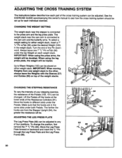
... is connected to the cam arm and the butterfly arms. To select a weight setting for each individual exercise. When using the press arms, the weight will be. Move the Leg Press Plate forward or backward and insert the "L" Pin through the Leg Press Plate and the Leg Press Frame (88). 84 91 100 101 90 88 89 20 ADJUSTING THE CROSS TRAINING SYSTEM The instructions below describe how each part of the cross training system...
... is connected to the cam arm and the butterfly arms. To select a weight setting for each individual exercise. When using the press arms, the weight will be. Move the Leg Press Plate forward or backward and insert the "L" Pin through the Leg Press Plate and the Leg Press Frame (88). 84 91 100 101 90 88 89 20 ADJUSTING THE CROSS TRAINING SYSTEM The instructions below describe how each part of the cross training system...

English Manual
Page 21
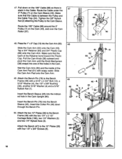
... Cam Sleeve and the Cam Upright (85). Pivot the Cam Arm to any of the seven adjustment holes in assembly step 49 on the Press Upright. Cr:4 4) 53 20 i , I 0) 43 ' 4© IIi c5 1., i ' 38 50 : 1 CHANGING THE HEIGHT OF THE PRESS SEAT The Seat (53) attached to the Press Upright (87) can be changed for different exercises. Slide the Bench Pin out of the Bench Pin (76). i.- 1 7.7,. 44 (' 0 II 49...
... Cam Sleeve and the Cam Upright (85). Pivot the Cam Arm to any of the seven adjustment holes in assembly step 49 on the Press Upright. Cr:4 4) 53 20 i , I 0) 43 ' 4© IIi c5 1., i ' 38 50 : 1 CHANGING THE HEIGHT OF THE PRESS SEAT The Seat (53) attached to the Press Upright (87) can be changed for different exercises. Slide the Bench Pin out of the Bench Pin (76). i.- 1 7.7,. 44 (' 0 II 49...
English Manual
Page 22
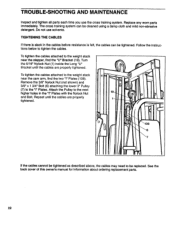
... worn parts immediately. Remove the 3/8" Nylock Nut (not shown) and 3/8" x 1 3/4" Bolt (6) attaching the lower 3" Pulley (7) to the next higher holes in the cables before resistance is felt, the cables can be replaced. Repeat until the cables are properly tightened. 108 6 7 If the cables cannot be tightened as described above, the cables may need to tighten the cables. TROUBLE-SHOOTING AND MAINTENANCE Inspect and tighten all parts each time you use solvents. Follow the instructions...
... worn parts immediately. Remove the 3/8" Nylock Nut (not shown) and 3/8" x 1 3/4" Bolt (6) attaching the lower 3" Pulley (7) to the next higher holes in the cables before resistance is felt, the cables can be replaced. Repeat until the cables are properly tightened. 108 6 7 If the cables cannot be tightened as described above, the cables may need to tighten the cables. TROUBLE-SHOOTING AND MAINTENANCE Inspect and tighten all parts each time you use solvents. Follow the instructions...
English Manual
Page 24
... abnormal usage or repairs not provided by WESLO. This warranty does not extend to any product or damage to a product caused by or attributable to give the following information: 1. ORDERING REPLACEMENT PARTS To order replacement parts, simply call our Customer Service Department toll-free at one of purchase. Mountain Time (excluding holidays). The MODEL NUMBER of the product (WESLO® BODY SHOP 9 cross training system). 3. SOME STATES...
... abnormal usage or repairs not provided by WESLO. This warranty does not extend to any product or damage to a product caused by or attributable to give the following information: 1. ORDERING REPLACEMENT PARTS To order replacement parts, simply call our Customer Service Department toll-free at one of purchase. Mountain Time (excluding holidays). The MODEL NUMBER of the product (WESLO® BODY SHOP 9 cross training system). 3. SOME STATES...


