
English Manual
Page 1
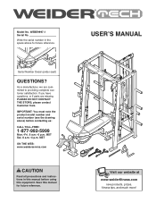
..., or if parts are committed to providing complete customer satisfaction. MST Sat. 8 a.m.-4 p.m. WEBE9997.1 Serial No. MST ON THE WEB: www.weiderservice.com CAUTION Read all precautions and instructions in the space above ) before using this manual before contacting us: CALL TOLL-FREE: 1-877-992-5999 Mon.-Fri. 6 a.m.-6 p.m. Write the serial number in this equipment. Serial Number Decal (under seat) QUESTIONS? Model No. Visit...
..., or if parts are committed to providing complete customer satisfaction. MST Sat. 8 a.m.-4 p.m. WEBE9997.1 Serial No. MST ON THE WEB: www.weiderservice.com CAUTION Read all precautions and instructions in the space above ) before using this manual before contacting us: CALL TOLL-FREE: 1-877-992-5999 Mon.-Fri. 6 a.m.-6 p.m. Write the serial number in this equipment. Serial Number Decal (under seat) QUESTIONS? Model No. Visit...
English Manual
Page 2
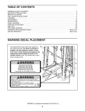
... BEGIN 4 PART IDENTIFICATION CHART 5 ASSEMBLY 6 ADJUSTMENT 14 MAINTENANCE 18 CABLE DIAGRAM 19 EXERCISE GUIDELINES 20 PART LIST 22 EXPLODED DRAWING 24 ORDERING REPLACEMENT PARTS Back Cover LIMITED WARRANTY Back Cover WARNING DECAL PLACEMENT The decals shown here have been applied in the location shown. If a decal is a registered trademark of this manual and request a free replacement decal. WEIDER is missing or illegible, call the telephone number on the front cover of ICON IP, Inc...
... BEGIN 4 PART IDENTIFICATION CHART 5 ASSEMBLY 6 ADJUSTMENT 14 MAINTENANCE 18 CABLE DIAGRAM 19 EXERCISE GUIDELINES 20 PART LIST 22 EXPLODED DRAWING 24 ORDERING REPLACEMENT PARTS Back Cover LIMITED WARRANTY Back Cover WARNING DECAL PLACEMENT The decals shown here have been applied in the location shown. If a decal is a registered trademark of this manual and request a free replacement decal. WEIDER is missing or illegible, call the telephone number on the front cover of ICON IP, Inc...
English Manual
Page 3
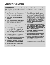
...row bar when performing an exercise that the cables remain on the pulleys at the same height. 13. Do not use of the weight bench. 1. Inspect and properly tighten all users of the weight bench are exercising, stop ...exercising, stop immediately and make sure that all parts regularly. Make sure that the pins and knobs are on the leg lever. Make sure that there is the responsibility of the weight carriage or barbell. 14. Always wear athletic shoes for home use it to ensure that the cables are fully engaged before using the weight bench. The weight bench is used...
...row bar when performing an exercise that the cables remain on the pulleys at the same height. 13. Do not use of the weight bench. 1. Inspect and properly tighten all users of the weight bench are exercising, stop ...exercising, stop immediately and make sure that all parts regularly. Make sure that the pins and knobs are on the leg lever. Make sure that there is the responsibility of the weight carriage or barbell. 14. Always wear athletic shoes for home use it to ensure that the cables are fully engaged before using the weight bench. The weight bench is used...
English Manual
Page 4
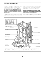
... weight bench will help us . ASSEMBLED DIMENSIONS: Height: 83 in. (211 cm) Width: 84 in. (213 cm) Depth: 110 in the manual. 4 The weight bench offers an impressive selection of exercise stations designed to achieve the specific results you have questions after reading this manual, please see the front cover of this manual carefully before contacting us assist you for any service needed under warranty...
... weight bench will help us . ASSEMBLED DIMENSIONS: Height: 83 in. (211 cm) Width: 84 in. (213 cm) Depth: 110 in the manual. 4 The weight bench offers an impressive selection of exercise stations designed to achieve the specific results you have questions after reading this manual, please see the front cover of this manual carefully before contacting us assist you for any service needed under warranty...
English Manual
Page 5
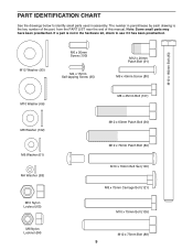
... identify small parts used in parentheses by each drawing is the key number of the part, from the PART LIST near the end of this manual. M10 x 183mm Bolt (83) M12 Washer (93) M6 x 20mm Screw (100) M4 x 15mm Self-tapping Screw (95) M12 x 20mm Patch Bolt (91) M6 x 40mm Screw (80)... 45mm Bolt (101) M12 x 63mm Patch Bolt (90) M12 x 70mm Patch Bolt (89) M10 x 70mm Bolt Set (106) M8 x 75mm Carriage Bolt (121) M10 x 75mm Bolt (105) M12 x 75mm Bolt (88) 5 The number in assembly. PART IDENTIFICATION CHART See the drawings below to see if it has been preattached. Note: Some small parts may...
... identify small parts used in parentheses by each drawing is the key number of the part, from the PART LIST near the end of this manual. M10 x 183mm Bolt (83) M12 Washer (93) M6 x 20mm Screw (100) M4 x 15mm Self-tapping Screw (95) M12 x 20mm Patch Bolt (91) M6 x 40mm Screw (80)... 45mm Bolt (101) M12 x 63mm Patch Bolt (90) M12 x 70mm Patch Bolt (89) M10 x 70mm Bolt Set (106) M8 x 75mm Carriage Bolt (121) M10 x 75mm Bolt (105) M12 x 75mm Bolt (88) 5 The number in assembly. PART IDENTIFICATION CHART See the drawings below to see if it has been preattached. Note: Some small parts may...
English Manual
Page 6
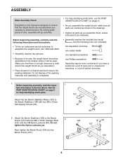
...; Assembly requires the included hex key(s) and the following information and instructions: • To hire an authorized service technician to ensure that the weight bench can be used. Attach the two Bench Stabilizer Plates (127) to the Bench 2 Frame (107) with four M4 x 15mm Self-tapping Screws (95). 127 95 2. Attach the Bench Stabilizer (108) to the Bench Stabilizer (108) with two M8 x 75mm Carriage Bolts...
...; Assembly requires the included hex key(s) and the following information and instructions: • To hire an authorized service technician to ensure that the weight bench can be used. Attach the two Bench Stabilizer Plates (127) to the Bench 2 Frame (107) with four M4 x 15mm Self-tapping Screws (95). 127 95 2. Attach the Bench Stabilizer (108) to the Bench Stabilizer (108) with two M8 x 75mm Carriage Bolts...
English Manual
Page 7
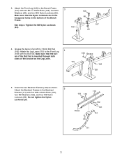
...the bracket on the Leg Lever. 110 106 Grease 106 109 5. Attach the Front Leg (109) to the Front Leg 4 (109) with the Bolt Set. Attach the Leg Lever (110) to the Bench Frame 3 (107) with four M8 x 45mm Bolts (101), four M8 Washers (102), and four M8 Nylon Locknuts (84). 3. See step 2. Make sure ... Locknuts (65). Tighten the M8 Nylon Locknuts (84). 109 105 66 107 65 4. Do not tighten the Nylon Locknuts yet. 118 101 102 Holes 84 102 101 84 111 7 rel of the Bolt Set is inserted through both sides of an M10 x 70mm Bolt Set (106). Make sure that the bar-
...the bracket on the Leg Lever. 110 106 Grease 106 109 5. Attach the Front Leg (109) to the Front Leg 4 (109) with the Bolt Set. Attach the Leg Lever (110) to the Bench Frame 3 (107) with four M8 x 45mm Bolts (101), four M8 Washers (102), and four M8 Nylon Locknuts (84). 3. See step 2. Make sure ... Locknuts (65). Tighten the M8 Nylon Locknuts (84). 109 105 66 107 65 4. Do not tighten the Nylon Locknuts yet. 118 101 102 Holes 84 102 101 84 111 7 rel of the Bolt Set is inserted through both sides of an M10 x 70mm Bolt Set (106). Make sure that the bar-
English Manual
Page 9
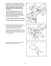
... the Leg Lever (110). Then, press a 19mm Round Cap (140) into each Short Pad Tube. Do not overtighten the Nylon Locknut; Then, insert the Seat Pin through the Seat Frame and the Bench Frame (107). 122 See step 5. Tighten the M6 x 40mm Screws (80). 95 123 107 10. Attach the Curl Pad (114) to the Seat Frame (122) with the Bolt, two...
... the Leg Lever (110). Then, press a 19mm Round Cap (140) into each Short Pad Tube. Do not overtighten the Nylon Locknut; Then, insert the Seat Pin through the Seat Frame and the Bench Frame (107). 122 See step 5. Tighten the M6 x 40mm Screws (80). 95 123 107 10. Attach the Curl Pad (114) to the Seat Frame (122) with the Bolt, two...
English Manual
Page 12
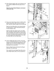
...) in the Right Upright (2). Then, attach the other Weight Rest (30) and the other Barbell Adapter (not shown) in the inset drawing and slide it downward as far as possible, and tighten the Nut against the Cable Eyelet. Remove the Cable Eyelet (104), the M8 Nut (99), and the Cable Stop (103) from the Low Cable (52). Route the Cable through the Foot...
...) in the Right Upright (2). Then, attach the other Weight Rest (30) and the other Barbell Adapter (not shown) in the inset drawing and slide it downward as far as possible, and tighten the Nut against the Cable Eyelet. Remove the Cable Eyelet (104), the M8 Nut (99), and the Cable Stop (103) from the Low Cable (52). Route the Cable through the Foot...
English Manual
Page 13
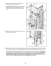
... for proper cable routing. 21. Tighten two M12 x 20mm Patch Bolts (91) into 21 the top Hinge Frames (5) as shown. If one of the remaining parts will need to make sure that all parts have been properly tightened. Note: Some hardware may be left over the pulleys. The use of the cables does not move smoothly over after assembly is used. See the CABLE DIAGRAM on...
... for proper cable routing. 21. Tighten two M12 x 20mm Patch Bolts (91) into 21 the top Hinge Frames (5) as shown. If one of the remaining parts will need to make sure that all parts have been properly tightened. Note: Some hardware may be left over the pulleys. The use of the cables does not move smoothly over after assembly is used. See the CABLE DIAGRAM on...
English Manual
Page 14
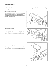
... page 20 for important information about how to see the correct form for several exercises. Move the Backrest to adjust the weight bench. ADJUSTING THE SEAT Hold the Seat (116) with one hand and disengage the Seat Pin (123) from your exercise program. Insert the Curl Post (113) into the Seat Frame and the Bench Frame (107). Also, refer to the accompanying exercise guide to get the most...
... page 20 for important information about how to see the correct form for several exercises. Move the Backrest to adjust the weight bench. ADJUSTING THE SEAT Hold the Seat (116) with one hand and disengage the Seat Pin (123) from your exercise program. Insert the Curl Post (113) into the Seat Frame and the Bench Frame (107). Also, refer to the accompanying exercise guide to get the most...

English Manual
Page 15
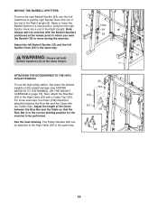
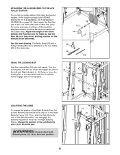
...), set the Weight Spotters (29) at the lowest point to which you want your barbell to move. WARNING: Always adjust both Weight Spotters (29) and both Weight Rests (30) to the Leg Lever (110) with the Curl Pin (115). 112 115 110 USING THE LEG LEVER To use the Leg Lever (110), slide the desired weights (not included) onto the Leg Lever. ATTACHING THE CURL BAR Attach...
...), set the Weight Spotters (29) at the lowest point to which you want your barbell to move. WARNING: Always adjust both Weight Spotters (29) and both Weight Rests (30) to the Leg Lever (110) with the Curl Pin (115). 112 115 110 USING THE LEG LEVER To use the Leg Lever (110), slide the desired weights (not included) onto the Leg Lever. ATTACHING THE CURL BAR Attach...
English Manual
Page 16
..., attach the Row Bar (63) to be performed. MOVING THE BARBELL SPOTTERS To move during the exercise. Adjust the length of the slot in the Right Upright (2). For some exercises, the Chain (142) should be attached to move the right Barbell Spotter (23), use the high pulley station, first place the desired weights on the weight carriage (see ADDING WEIGHTS TO THE BARBELL OR THE WEIGHT...
..., attach the Row Bar (63) to be performed. MOVING THE BARBELL SPOTTERS To move during the exercise. Adjust the length of the slot in the Right Upright (2). For some exercises, the Chain (142) should be attached to move the right Barbell Spotter (23), use the high pulley station, first place the desired weights on the weight carriage (see ADDING WEIGHTS TO THE BARBELL OR THE WEIGHT...
English Manual
Page 17
.... USING THE LOCKING BAR Grip the Locking Bar (19) with a Cable Clip (151). For some exercises, the Chain (142) should be performed. The Ankle Strap (26) and a Pulley Handle (25) can be attached to a new position and turn it until the two hooks disengage the slots in the Uprights. 52 151 63 25 26 142 2 Hook 1 19 ADJUSTING THE ARMS To change the...
.... USING THE LOCKING BAR Grip the Locking Bar (19) with a Cable Clip (151). For some exercises, the Chain (142) should be performed. The Ankle Strap (26) and a Pulley Handle (25) can be attached to a new position and turn it until the two hooks disengage the slots in the Uprights. 52 151 63 25 26 142 2 Hook 1 19 ADJUSTING THE ARMS To change the...
English Manual
Page 18
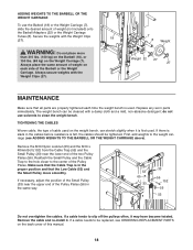
..., non-abrasive detergent; Weight 22 27 27 MAINTENANCE Make sure that all parts are properly tightened each side of the two Pulley Plates (56). If a cable tends to slip off the pulleys often, it . ADDING WEIGHTS TO THE BARBELL OR THE WEIGHT CARRIAGE To use solvents to clean the weight bench. Make sure that the Low Cable (52) and the Small Pulley move smoothly. do not...
..., non-abrasive detergent; Weight 22 27 27 MAINTENANCE Make sure that all parts are properly tightened each side of the two Pulley Plates (56). If a cable tends to slip off the pulleys often, it . ADDING WEIGHTS TO THE BARBELL OR THE WEIGHT CARRIAGE To use solvents to clean the weight bench. Make sure that the Low Cable (52) and the Small Pulley move smoothly. do not...
English Manual
Page 20
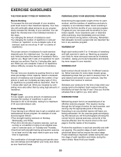
... their maximum capacity. Cross Training Cross training is one complete cycle of rest. EXERCISE FORM Maintaining proper form is right for each set smoothly and without pausing. See the muscle chart on Tuesday and Thursday. • Rest from workout to workout. Remember that you . WARMING UP The proper amount of an effective exercise program. Select a moderate amount of resistance and increase the number of resistance. Work your muscles...
... their maximum capacity. Cross Training Cross training is one complete cycle of rest. EXERCISE FORM Maintaining proper form is right for each set smoothly and without pausing. See the muscle chart on Tuesday and Thursday. • Rest from workout to workout. Remember that you . WARMING UP The proper amount of an effective exercise program. Select a moderate amount of resistance and increase the number of resistance. Work your muscles...
English Manual
Page 21
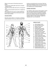
...; Rest for three minutes after each set for a weight loss workout. Move slowly as you stretch and do not bounce. List the date, the exercises performed, the resistance used, and the numbers of calf) K. Triceps (back of arm) D. Spinae Erectors (lower back) U. Obliques (waist) E. building workout. • Rest for one minute after each workout. Include stretches for a toning work- STAYING MOTIVATED For motivation, keep...
...; Rest for three minutes after each set for a weight loss workout. Move slowly as you stretch and do not bounce. List the date, the exercises performed, the resistance used, and the numbers of calf) K. Triceps (back of arm) D. Spinae Erectors (lower back) U. Obliques (waist) E. building workout. • Rest for one minute after each workout. Include stretches for a toning work- STAYING MOTIVATED For motivation, keep...
English Manual
Page 22
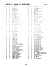
... Butterfly Adjustment Knob Barbell Guide Barbell Locking Bar Barbell Carriage "V"-pulley Barbell Adapter Barbell Spotter Spotter Hook Pulley Handle Ankle Strap Weight Clip Foot Plate Weight Spotter Weight Rest Upright Plate Swivel Bracket Small Pulley Large Pulley 75mm x 50mm Outer Cap 127mm x 50mm Outer Cap Rack Foot 38mm Square Outer Cap Weight Spotter Pad Weight Rest Pad 75mm x 38mm Outer Cap 75mm x 38mm Leaning Cap Large Cable...
... Butterfly Adjustment Knob Barbell Guide Barbell Locking Bar Barbell Carriage "V"-pulley Barbell Adapter Barbell Spotter Spotter Hook Pulley Handle Ankle Strap Weight Clip Foot Plate Weight Spotter Weight Rest Upright Plate Swivel Bracket Small Pulley Large Pulley 75mm x 50mm Outer Cap 127mm x 50mm Outer Cap Rack Foot 38mm Square Outer Cap Weight Spotter Pad Weight Rest Pad 75mm x 38mm Outer Cap 75mm x 38mm Leaning Cap Large Cable...
English Manual
Page 23
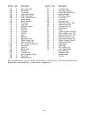
... Screw Leg Bumper Curl Knob Leg Lever Cap 48mm Thick Round Cap 56mm Square Cap 19mm Round Cap Curl Bumper Chain 127mm x 50mm Inner Cap 75mm x 50mm Inner Cap 75mm x 38mm Inner Cap 28mm Round Inner cap 63.5mm Round Inner Cap Weight Carriage Bumper 50mm Square Cap Cable Guard Cable Clip M10 x 48mm Bolt Lower Cable Eyelet User's Manual Exercise Guide Grease Packet Hex Key...
... Screw Leg Bumper Curl Knob Leg Lever Cap 48mm Thick Round Cap 56mm Square Cap 19mm Round Cap Curl Bumper Chain 127mm x 50mm Inner Cap 75mm x 50mm Inner Cap 75mm x 38mm Inner Cap 28mm Round Inner cap 63.5mm Round Inner Cap Weight Carriage Bumper 50mm Square Cap Cable Guard Cable Clip M10 x 48mm Bolt Lower Cable Eyelet User's Manual Exercise Guide Grease Packet Hex Key...

English Manual
Page 28
... by an ICON authorized service center; Accordingly, the above limitation may not apply to replacing or repairing, at ICON's option, the product through one of merchantability or fitness for which vary from the date of this manual) • the key number and description of the part(s) (see the front cover of purchase. ICON's obligation under normal use , costs of removal or installation or other warranties and any...
... by an ICON authorized service center; Accordingly, the above limitation may not apply to replacing or repairing, at ICON's option, the product through one of merchantability or fitness for which vary from the date of this manual) • the key number and description of the part(s) (see the front cover of purchase. ICON's obligation under normal use , costs of removal or installation or other warranties and any...


