
English Manual
Page 2
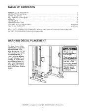
...; Do not allow children on or around machine. • Replace label if damaged, illegible, or removed. Remove the PART LIST/EXPLODED DRAWING before beginning assembly. WEIDER is not legible, please call our toll-free HELPLINE at the right has been applied to order a free replacement decal. Apply the replacement decal in... IDENTIFICATION CHART 5 ASSEMBLY 6 ADJUSTMENTS 12 EXERCISE GUIDELINES 14 ORDERING REPLACEMENT PARTS Back Cover FULL 90-DAY WARRANTY Back Cover Note: A PART LIST/EXPLODED DRAWING is attached in the center of this manual.
...; Do not allow children on or around machine. • Replace label if damaged, illegible, or removed. Remove the PART LIST/EXPLODED DRAWING before beginning assembly. WEIDER is not legible, please call our toll-free HELPLINE at the right has been applied to order a free replacement decal. Apply the replacement decal in... IDENTIFICATION CHART 5 ASSEMBLY 6 ADJUSTMENTS 12 EXERCISE GUIDELINES 14 ORDERING REPLACEMENT PARTS Back Cover FULL 90-DAY WARRANTY Back Cover Note: A PART LIST/EXPLODED DRAWING is attached in the center of this manual.
English Manual
Page 4
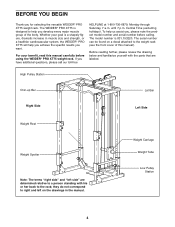
...left on a decal attached to help us assist you develop every major muscle group of this manual carefully before calling. Weight Carriage Weight Tube Low Pulley Station 4 For your goal is a shapely figure, dramatic increase in the manual. If you want. The WEIDER® PRO XT75 is 831.153220. ...until 7 p.m. The serial number can be found on the drawings in muscle size and strength, or a healthier cardiovascular system, the WEIDER® PRO XT75 will help you achieve the specific results you have additional questions, please call our toll-free HELPLINE at 1-800-736-6879, Monday ...
...left on a decal attached to help us assist you develop every major muscle group of this manual carefully before calling. Weight Carriage Weight Tube Low Pulley Station 4 For your goal is a shapely figure, dramatic increase in the manual. If you want. The WEIDER® PRO XT75 is 831.153220. ...until 7 p.m. The serial number can be found on the drawings in muscle size and strength, or a healthier cardiovascular system, the WEIDER® PRO XT75 will help you achieve the specific results you have additional questions, please call our toll-free HELPLINE at 1-800-736-6879, Monday ...
English Manual
Page 5
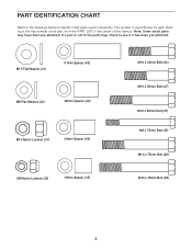
... (47) M10 x 66mm Bolt (37) M8 x 72mm Bolt (35) M10 x 75mm Bolt (36) M10 x 78mm Bolt (33) 5 Note: Some small parts may have been pre-attached. If a part is the key number of this manual. PART IDENTIFICATION CHART Refer to the drawings below to see if it has been pre...
... (47) M10 x 66mm Bolt (37) M8 x 72mm Bolt (35) M10 x 75mm Bolt (36) M10 x 78mm Bolt (33) 5 Note: Some small parts may have been pre-attached. If a part is the key number of this manual. PART IDENTIFICATION CHART Refer to the drawings below to see if it has been pre...
English Manual
Page 6
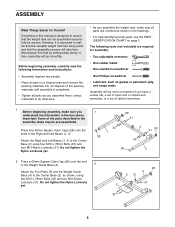
...the weight rack, make sure you have a socket set, a set of open-end or closed-end wrenches, or a set of the Weight Guide Base (4). 2 Attach the Foot Plate (5) and the Weight Guide Base (4) to realize that the versatile weight rack has many parts and that the weight rack can be...M10 Nylon Locknuts (31). Important: Some of the Right and Left Bases (1, 3). Press a 60mm Square Outer Cap (28) onto the end of ratchet wrenches. 1. Attach the Right and Left Bases (1, 3) to ensure that the assembly process will go smoothly. Do not tighten the Nylon Locknuts yet. 28 4 2 31 31 5 33...
...the weight rack, make sure you have a socket set, a set of open-end or closed-end wrenches, or a set of the Weight Guide Base (4). 2 Attach the Foot Plate (5) and the Weight Guide Base (4) to realize that the versatile weight rack has many parts and that the weight rack can be...M10 Nylon Locknuts (31). Important: Some of the Right and Left Bases (1, 3). Press a 60mm Square Outer Cap (28) onto the end of ratchet wrenches. 1. Attach the Right and Left Bases (1, 3) to ensure that the assembly process will go smoothly. Do not tighten the Nylon Locknuts yet. 28 4 2 31 31 5 33...
English Manual
Page 7
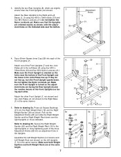
...shorter than the Front Uprights (not shown). Make sure that the Uprights are oriented exactly as shown. Do not tighten the Nylon Locknuts yet. Attach the Rear Uprights to drawing 5b. Tap a 60mm Square Inner Cap (29) into an adjustment hole in the Uprights. 20 Assemble the Left... 21 22 21 8 7 3 29 8 7 31 3 6 31 5b 8 7 19 22 22 20 Refer to the right Uprights (7, 8) by tightening each of the Front Uprights (7). 4 Attach one of the three Adjustment Knobs (22) into each of the Front Uprights (7) and two Joint Plates (6) to the Right Base 6 (1) in the same manner...
...shorter than the Front Uprights (not shown). Make sure that the Uprights are oriented exactly as shown. Do not tighten the Nylon Locknuts yet. Attach the Rear Uprights to drawing 5b. Tap a 60mm Square Inner Cap (29) into an adjustment hole in the Uprights. 20 Assemble the Left... 21 22 21 8 7 3 29 8 7 31 3 6 31 5b 8 7 19 22 22 20 Refer to the right Uprights (7, 8) by tightening each of the Front Uprights (7). 4 Attach one of the three Adjustment Knobs (22) into each of the Front Uprights (7) and two Joint Plates (6) to the Right Base 6 (1) in the same manner...
English Manual
Page 8
... Carriage (15). Press the two Carriage Bushings (16) into the weight tubes on top of the Weight Bumpers. Do not tighten the Nylon Locknuts yet. Attach the Weight Guides using four M10 x 78mm 6 6 Bolts (33) and four M10 Nylon Locknuts (31). 6. Set the two Weight Bumpers (18) over the... the Weight Carriage (15). Press a 60mm Square Inner Cap (29) into the Weight Carriage (15), the Weight Bumpers (18), and the Weight Guide Base (4). Attach the Center Frame (11) to the left Uprights (7, 8) using four M10 x 78mm Bolts (33) and four M10 Nylon Locknuts (31). Make sure the Weight ...
... Carriage (15). Press the two Carriage Bushings (16) into the weight tubes on top of the Weight Bumpers. Do not tighten the Nylon Locknuts yet. Attach the Weight Guides using four M10 x 78mm 6 6 Bolts (33) and four M10 Nylon Locknuts (31). 6. Set the two Weight Bumpers (18) over the... the Weight Carriage (15). Press a 60mm Square Inner Cap (29) into the Weight Carriage (15), the Weight Bumpers (18), and the Weight Guide Base (4). Attach the Center Frame (11) to the left Uprights (7, 8) using four M10 x 78mm Bolts (33) and four M10 Nylon Locknuts (31). Make sure the Weight ...

English Manual
Page 9
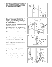
...two M10 Nylon Locknuts (31). 9 25 31 26 14 47 Route the metal-sleeve end of the two Cables. Attach the Weight Guide Frame (14) to the Weight Guide Frame using two M10 x 78mm Bolts (33), two M10... Flat Washers (41), and two M10 Nylon Locknuts (31). 11. Attach two Pulleys (25) inside the bracket on the 13 Weight Guide Frame (14) using an M10 x 66mm Bolt (37...two 24mm Spacers (42), and an M10 Nylon Locknut (31). 31 41 42 15 26 42 41 37 13. Attach the Weight Guides to the Center Frame (11) using two M8 x 72mm Bolts (35), four M8 Flat Washers ...
...two M10 Nylon Locknuts (31). 9 25 31 26 14 47 Route the metal-sleeve end of the two Cables. Attach the Weight Guide Frame (14) to the Weight Guide Frame using two M10 x 78mm Bolts (33), two M10... Flat Washers (41), and two M10 Nylon Locknuts (31). 11. Attach two Pulleys (25) inside the bracket on the 13 Weight Guide Frame (14) using an M10 x 66mm Bolt (37...two 24mm Spacers (42), and an M10 Nylon Locknut (31). 31 41 42 15 26 42 41 37 13. Attach the Weight Guides to the Center Frame (11) using two M8 x 72mm Bolts (35), four M8 Flat Washers ...
English Manual
Page 10
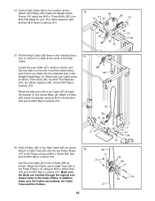
... the Low Cable (27) through the highest and lowest holes in the High Cable (26) as shown. Attach the Low Cable using an M10 x 45mm Bolt (34) and an M10 Nylon Locknut (31). Route the...and two M10 Nylon Locknuts (31). 14 25 31 41 45 26 14 41 45 45 41 45 41 36 15. Attach a Pulley (25) inside the Weight Guide Frame (14) using an M10 x 45mm Bolt (34) and an M10 ...Hold a Pulley (25) in the Pulley Plates. 14. Lay the Low Cable (27) over a Pulley (25) as shown. 16 Attach a Cable Trap (24) and the two Pulley Plates (17) to the Pulley Plates (17) using an M10 x 75mm Bolt (36...
... the Low Cable (27) through the highest and lowest holes in the High Cable (26) as shown. Attach the Low Cable using an M10 x 45mm Bolt (34) and an M10 Nylon Locknut (31). Route the...and two M10 Nylon Locknuts (31). 14 25 31 41 45 26 14 41 45 45 41 45 41 36 15. Attach a Pulley (25) inside the Weight Guide Frame (14) using an M10 x 45mm Bolt (34) and an M10 ...Hold a Pulley (25) in the Pulley Plates. 14. Lay the Low Cable (27) over a Pulley (25) as shown. 16 Attach a Cable Trap (24) and the two Pulley Plates (17) to the Pulley Plates (17) using an M10 x 75mm Bolt (36...
English Manual
Page 13
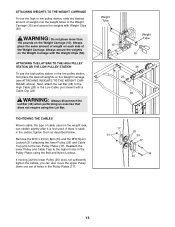
... 13 WARNING: Do not place more than 150 pounds on the Weight Carriage (see ATTACHING WEIGHTS TO THE WEIGHT CARRIAGE, above). ATTACHING THE LAT BAR TO THE HIGH PULLEY STATION OR THE LOW PULLEY STATION To use ...If there is first used. Remove the M10 x 45mm Bolt (34) and the M10 Nylon Locknut (31) attaching the lower Pulley (25) and Cable Trap (24) to the High Cable (26) or the Low Cable (not ...shown) with Weight Clips (50). ATTACHING WEIGHTS TO THE WEIGHT CARRIAGE To use the high pulley station or the low pulley station, first place the...
... 13 WARNING: Do not place more than 150 pounds on the Weight Carriage (see ATTACHING WEIGHTS TO THE WEIGHT CARRIAGE, above). ATTACHING THE LAT BAR TO THE HIGH PULLEY STATION OR THE LOW PULLEY STATION To use ...If there is first used. Remove the M10 x 45mm Bolt (34) and the M10 Nylon Locknut (31) attaching the lower Pulley (25) and Cable Trap (24) to the High Cable (26) or the Low Cable (not ...shown) with Weight Clips (50). ATTACHING WEIGHTS TO THE WEIGHT CARRIAGE To use the high pulley station or the low pulley station, first place the...
English Manual
Page 18
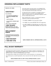
...see the PART LIST and the EXPLODED DRAWING in China © 2001 ICON Health & Fitness, Inc. All replacement parts are listed on a decal attached to find that: • you find the location of this manual) SEARS, ROEBUCK AND CO., HOFFMAN ESTATES, IL 60179 FULL 90-DAY WARRANTY For...tollfree number 1-800-FON-PART (1-800-366-7278) The model number and serial number of charge. When requesting help assembling or operating the WEIDER® PRO XT75 • a part is used commercially or for immediate purchase or special order when you need to schedule repair service call our toll-...
...see the PART LIST and the EXPLODED DRAWING in China © 2001 ICON Health & Fitness, Inc. All replacement parts are listed on a decal attached to find that: • you find the location of this manual) SEARS, ROEBUCK AND CO., HOFFMAN ESTATES, IL 60179 FULL 90-DAY WARRANTY For...tollfree number 1-800-FON-PART (1-800-366-7278) The model number and serial number of charge. When requesting help assembling or operating the WEIDER® PRO XT75 • a part is used commercially or for immediate purchase or special order when you need to schedule repair service call our toll-...

