

User Manual
Page 1
Keep this equipment. Write the serial number in this manual before using this manual for future reference. WEIGHT SYSTEM EXERCISER Userʼs Manual Serial Number Decal (under seat) • Assembly • Adjustment • Troubleshooting • Part List and Drawing Sears, Roebuck and Co. Model No. 831.14622.1 Serial No. Hoffman Estates, IL 60179 CAUTION Read all precautions and instructions in the space above for future reference.
Keep this equipment. Write the serial number in this manual before using this manual for future reference. WEIGHT SYSTEM EXERCISER Userʼs Manual Serial Number Decal (under seat) • Assembly • Adjustment • Troubleshooting • Part List and Drawing Sears, Roebuck and Co. Model No. 831.14622.1 Serial No. Hoffman Estates, IL 60179 CAUTION Read all precautions and instructions in the space above for future reference.
User Manual
Page 2
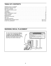
TABLE OF CONTENTS WARNING DECAL PLACEMENT 2 IMPORTANT PRECAUTIONS 3 BEFORE YOU BEGIN 4 PART IDENTIFICATION CHART 5 ASSEMBLY 8 ADJUSTMENT 25 WEIGHT RESISTANCE CHART 27 CABLE DIAGRAM 28 MAINTENANCE 29 EXERCISE GUIDELINES 30 PART LIST 33 EXPLODED DRAWING 34 ORDERING REPLACEMENT PARTS Back Cover ...
TABLE OF CONTENTS WARNING DECAL PLACEMENT 2 IMPORTANT PRECAUTIONS 3 BEFORE YOU BEGIN 4 PART IDENTIFICATION CHART 5 ASSEMBLY 8 ADJUSTMENT 25 WEIGHT RESISTANCE CHART 27 CABLE DIAGRAM 28 MAINTENANCE 29 EXERCISE GUIDELINES 30 PART LIST 33 EXPLODED DRAWING 34 ORDERING REPLACEMENT PARTS Back Cover ...
User Manual
Page 4
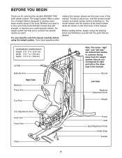
...Seat Seat Adjustment Knob Ankle Strap Handle 4 Whether your goal is to right and left side" are labeled. If you for selecting the versatile WEIDER® PRO 4300 weight system. The model number and the location of the serial number decal are shown on the drawings in . (196 cm) Lat Bar... "left on the front cover of this manual. The weight system offers a selection of weight stations designed to a person facing away from the weight system; ASSEMBLED DIMENSIONS: Height: 6 ft. 11 in. (210 cm) Width: 3 ft. 7 in. (109 cm) Depth: 3 ft. 5 in the manual. BEFORE YOU BEGIN Thank you...
...Seat Seat Adjustment Knob Ankle Strap Handle 4 Whether your goal is to right and left side" are labeled. If you for selecting the versatile WEIDER® PRO 4300 weight system. The model number and the location of the serial number decal are shown on the drawings in . (196 cm) Lat Bar... "left on the front cover of this manual. The weight system offers a selection of weight stations designed to a person facing away from the weight system; ASSEMBLED DIMENSIONS: Height: 6 ft. 11 in. (210 cm) Width: 3 ft. 7 in. (109 cm) Depth: 3 ft. 5 in the manual. BEFORE YOU BEGIN Thank you...
User Manual
Page 5
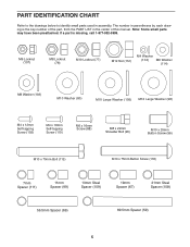
... manual. PART IDENTIFICATION CHART Refer to the drawings below to identify small parts used in the center of the part, from the PART LIST in assembly. M6 Locknut (107) M8 Locknut (78) M10 Locknut (77) M12 Nut (112) M4 Washer (104) M6 Washer (114) M8 Washer (103) M10 Washer (80) M10...
... manual. PART IDENTIFICATION CHART Refer to the drawings below to identify small parts used in the center of the part, from the PART LIST in assembly. M6 Locknut (107) M8 Locknut (78) M10 Locknut (77) M12 Nut (112) M4 Washer (104) M6 Washer (114) M8 Washer (103) M10 Washer (80) M10...
User Manual
Page 8
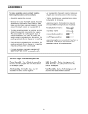
... the following tools (not included): two adjustable wrenches one rubber mallet one standard screwdriver one Phillips screwdriver Assembly may be more convenient if you assemble it will begin by assembling the base and the uprights that connect the arms to walk around the weight system as you have...Make sure that there is completed. • For help identifying small parts, use the PART IDENTIFICATION CHART on pages 5 and 6. • As you assemble the weight system, make sure all parts are found in a cleared area and remove the packing materials. Do not dispose of the packing. • ...
... the following tools (not included): two adjustable wrenches one rubber mallet one standard screwdriver one Phillips screwdriver Assembly may be more convenient if you assemble it will begin by assembling the base and the uprights that connect the arms to walk around the weight system as you have...Make sure that there is completed. • For help identifying small parts, use the PART IDENTIFICATION CHART on pages 5 and 6. • As you assemble the weight system, make sure all parts are found in a cleared area and remove the packing materials. Do not dispose of the packing. • ...

User Manual
Page 9
Frame Assembly 1 1. Do not tighten the Locknuts yet. 2 2 78 3. Do not tighten the Locknuts yet. Insert four M8 x 75mm Carriage Bolts (83) up . 1 83 83 18 Holes ... (2) to the Base (1) with two M10 x 85mm Bolts (81), two M10 Washers (80), two 21mm Steel Spacers (108), and two M10 Locknuts (77). Before beginning assembly, make sure that the indicated holes are closer to the Stabilizer (3) with the two indicated M8 x 75mm Carriage Bolts (83) and two M8 Locknuts (78...
Frame Assembly 1 1. Do not tighten the Locknuts yet. 2 2 78 3. Do not tighten the Locknuts yet. Insert four M8 x 75mm Carriage Bolts (83) up . 1 83 83 18 Holes ... (2) to the Base (1) with two M10 x 85mm Bolts (81), two M10 Washers (80), two 21mm Steel Spacers (108), and two M10 Locknuts (77). Before beginning assembly, make sure that the indicated holes are closer to the Stabilizer (3) with the two indicated M8 x 75mm Carriage Bolts (83) and two M8 Locknuts (78...
User Manual
Page 12
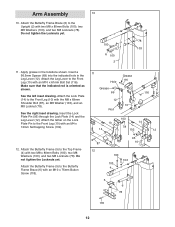
... Lever (12). Attach the tether on the Lock Plate Pin to the Front Leg (10) with an M4 x 12mm Self-tapping Screw (102). 12. Arm Assembly 10 10. Make sure that the indicated rod is oriented as shown. See the left inset drawing. Insert the Lock Plate Pin (95) through the...
... Lever (12). Attach the tether on the Lock Plate Pin to the Front Leg (10) with an M4 x 12mm Self-tapping Screw (102). 12. Arm Assembly 10 10. Make sure that the indicated rod is oriented as shown. See the left inset drawing. Insert the Lock Plate Pin (95) through the...

User Manual
Page 15
... (77). Attach the Cable to identify the cables as shown. 48 86 55 50 77 55 61 15 ented as you assemble them. Grease an M8 x 22mm Shoulder Bolt (90). Cable Assembly 19 19. See the CABLE DIAGRAMS on page 28 to the Left Butterfly Bracket (28) with the Shoulder Bolt and...
... (77). Attach the Cable to identify the cables as shown. 48 86 55 50 77 55 61 15 ented as you assemble them. Grease an M8 x 22mm Shoulder Bolt (90). Cable Assembly 19 19. See the CABLE DIAGRAMS on page 28 to the Left Butterfly Bracket (28) with the Shoulder Bolt and...
User Manual
Page 22
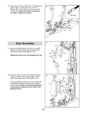
Make sure that the Adjustment Knob passes through one of the Cable is against the Spacer. 2 Flat Edge 115 80 111 51 77 Seat Assembly 41 26 41. Insert the Backrest Frame (7) into the Upright (2) and tighten the Backrest Adjustment Knob (53) into the Upright. 40. Attach the Leg Lever ...
Make sure that the Adjustment Knob passes through one of the Cable is against the Spacer. 2 Flat Edge 115 80 111 51 77 Seat Assembly 41 26 41. Insert the Backrest Frame (7) into the Upright (2) and tighten the Backrest Adjustment Knob (53) into the Upright. 40. Attach the Leg Lever ...

User Manual
Page 28
... The cable diagram shows the proper routing of the cables. The numbers in . (588 cm) 6 7 3 8 9 1 5 2 10 28 If the cables and the cable traps are assembled correctly. Make sure that the cable traps do not touch or bind the cables. 2 5 1 4 Lat Cable (49) Length 147 in. (373 cm) 3 1 3 Butterfly Cable (50.... (289 cm) 4 2 Leg Lever Cable (51) Length 231 in each drawing show the proper routing for that the cables and the cable traps are not assembled correctly, the weight system will not function properly and damage may occur.
... The cable diagram shows the proper routing of the cables. The numbers in . (588 cm) 6 7 3 8 9 1 5 2 10 28 If the cables and the cable traps are assembled correctly. Make sure that the cable traps do not touch or bind the cables. 2 5 1 4 Lat Cable (49) Length 147 in. (373 cm) 3 1 3 Butterfly Cable (50.... (289 cm) 4 2 Leg Lever Cable (51) Length 231 in each drawing show the proper routing for that the cables and the cable traps are not assembled correctly, the weight system will not function properly and damage may occur.

User Manual
Page 33
... 3 50mm Round Inner 81 2 M10 x 85mm Bolt 119 2 38mm Round Inner Cap 82 2 M10 x 75mm Bolt Cap 40 2 Press Arm Cap 83 5 M8 x 75mm Carriage * - Assembly Tool 42 2 40mm x 25mm Inner 85 4 M10 x 65mm Bolt * -
... 3 50mm Round Inner 81 2 M10 x 85mm Bolt 119 2 38mm Round Inner Cap 82 2 M10 x 75mm Bolt Cap 40 2 Press Arm Cap 83 5 M8 x 75mm Carriage * - Assembly Tool 42 2 40mm x 25mm Inner 85 4 M10 x 65mm Bolt * -


