
English Manual
Page 2
Remove the PART IDENTIFICATION CHART and the PART LIST/EXPLODED DRAWING before beginning assembly. 2 TABLE OF CONTENTS IMPORTANT PRECAUTIONS 3 BEFORE YOU BEGIN 4 ASSEMBLY 5 ADJUSTMENTS 21 WEIGHT RESISTANCE CHART 23 CABLE DIAGRAM 24 EXERCISE GUIDELINES 26 ORDERING REPLACEMENT PARTS Back Cover FULL 90 DAY WARRANTY Back Cover Note: A PART IDENTIFICATION CHART and a PART LIST/EXPLODED DRAWING are attached in the center of this manual.
Remove the PART IDENTIFICATION CHART and the PART LIST/EXPLODED DRAWING before beginning assembly. 2 TABLE OF CONTENTS IMPORTANT PRECAUTIONS 3 BEFORE YOU BEGIN 4 ASSEMBLY 5 ADJUSTMENTS 21 WEIGHT RESISTANCE CHART 23 CABLE DIAGRAM 24 EXERCISE GUIDELINES 26 ORDERING REPLACEMENT PARTS Back Cover FULL 90 DAY WARRANTY Back Cover Note: A PART IDENTIFICATION CHART and a PART LIST/EXPLODED DRAWING are attached in the center of this manual.
English Manual
Page 3
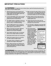
...tip. 3. Keep children under the age of this area. until 7 p.m. Always stand on a level surface. Cover the floor or carpet beneath the weight system to order a free replacement decal. Replace any exercise program, consult your physician. Never release the press arm, butterfly arms, leg lever, leg... press base, lat bar, ab strap, or handle while weights are on the pulleys at any time while exercising, stop immediately and make sure that the cables remain on all times. 7. If a decal ...
...tip. 3. Keep children under the age of this area. until 7 p.m. Always stand on a level surface. Cover the floor or carpet beneath the weight system to order a free replacement decal. Replace any exercise program, consult your physician. Never release the press arm, butterfly arms, leg lever, leg... press base, lat bar, ab strap, or handle while weights are on the pulleys at any time while exercising, stop immediately and make sure that the cables remain on all times. 7. If a decal ...
English Manual
Page 4
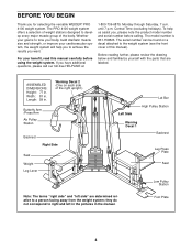
...-free HELPLINE at 1-800-736-6879, Monday through Saturday, 7 a.m. If you for selecting the versatile WEIDER® PRO 4100 weight system. until 7 p.m. To help you to a person facing away from the weight system; Foot Plate 4 The PRO 4100 weight system offers a selection of weight stations designed to tone your body, build dramatic muscle size and strength, or improve your...
...-free HELPLINE at 1-800-736-6879, Monday through Saturday, 7 a.m. If you for selecting the versatile WEIDER® PRO 4100 weight system. until 7 p.m. To help you to a person facing away from the weight system; Foot Plate 4 The PRO 4100 weight system offers a selection of weight stations designed to tone your body, build dramatic muscle size and strength, or improve your...
English Manual
Page 5
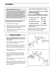
...one Phillips screwdriver • lubricant, such as grease or petroleum jelly, and soapy water. However, it is designed to realize that the versatile weight system has many parts and that by anyone. An Allen wrench (included) and the following information and instructions: • Assembly requires two people.... • Place all parts are oriented as you assemble them, unless instructed to do otherwise. • As you assemble the weight system, make sure all parts in this manual is important to ensure that you have read the following tools (not included) are required ...
...one Phillips screwdriver • lubricant, such as grease or petroleum jelly, and soapy water. However, it is designed to realize that the versatile weight system has many parts and that by anyone. An Allen wrench (included) and the following information and instructions: • Assembly requires two people.... • Place all parts are oriented as you assemble them, unless instructed to do otherwise. • As you assemble the weight system, make sure all parts in this manual is important to ensure that you have read the following tools (not included) are required ...

English Manual
Page 7
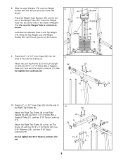
... in the Center Base (67). Do not tighten the 5/16" Nylon Locknuts (71) yet. 5 59 5 59 26 71 26 6 73 26 71 26 6. Attach the Weight Guides to the Left Upright (7) with two 5/16" x 2 1/2" Carriage Bolts (57) and two 5/16" Nylon Locknuts (71). 5. Do not tighten the 5/16" Nylon ...Locknuts (71) yet. 7. Insert the two Weight Guides (20) into the end of the Left Seat Frame (29). Attach the Right Seat Frame (5) to the Right Upright (6) with two 5/16" x 3 1/4" Bolts (59...
... in the Center Base (67). Do not tighten the 5/16" Nylon Locknuts (71) yet. 5 59 5 59 26 71 26 6 73 26 71 26 6. Attach the Weight Guides to the Left Upright (7) with two 5/16" x 2 1/2" Carriage Bolts (57) and two 5/16" Nylon Locknuts (71). 5. Do not tighten the 5/16" Nylon ...Locknuts (71) yet. 7. Insert the two Weight Guides (20) into the end of the Left Seat Frame (29). Attach the Right Seat Frame (5) to the Right Upright (6) with two 5/16" x 3 1/4" Bolts (59...
English Manual
Page 8
...Frame (8). Do not tighten the 5/16" Nylon Locknuts (71) yet. 10 59 21 8 22 71 3 71 71 6 26 60 8 Slide the Top Weight onto the Weight Guides (20), with the pin groove on the side shown. Do not tighten the Locknuts yet. 9 22 3 59 21 71 22 71 7 10. ... with two 5/16" x 3 1/4" Bolts (59), a Support Plate (21), and two 5/16" Nylon Locknuts (71). Insert the Weight Tube into the bottom of Weights (72). Lubricate the indicated holes in the stack of the Weight Tube (82). Attach the Right Top Frame (8) to the Left Upright (7) with two 5/16" x 2 3/4" Bolts (60), two ...
...Frame (8). Do not tighten the 5/16" Nylon Locknuts (71) yet. 10 59 21 8 22 71 3 71 71 6 26 60 8 Slide the Top Weight onto the Weight Guides (20), with the pin groove on the side shown. Do not tighten the Locknuts yet. 9 22 3 59 21 71 22 71 7 10. ... with two 5/16" x 3 1/4" Bolts (59), a Support Plate (21), and two 5/16" Nylon Locknuts (71). Insert the Weight Tube into the bottom of Weights (72). Lubricate the indicated holes in the stack of the Weight Tube (82). Attach the Right Top Frame (8) to the Left Upright (7) with two 5/16" x 2 3/4" Bolts (60), two ...
English Manual
Page 9
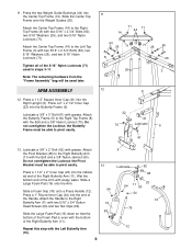
Press the two Weight Guide Bushings (44) into the Right Upright (6). ARM ASSEMBLY 12. Lubricate a 3/8" x 3" Bolt (61) with grease. Attach the Butterfly Frame (9) to the Left Top Frame (3) with ... of the Foam Pad is even with two 5/16" x 3/4" Button Head Screws (64) and two Nut Clips (99). Slide the Center Top Frame onto the Weight Guides (20). Attach the Pivot Bracket (48) to the Right Butterfly Arm (11) with the bottom of the Handle. Slide a Foam Grip (76) onto a Press...
Press the two Weight Guide Bushings (44) into the Right Upright (6). ARM ASSEMBLY 12. Lubricate a 3/8" x 3" Bolt (61) with grease. Attach the Butterfly Frame (9) to the Left Top Frame (3) with ... of the Foam Pad is even with two 5/16" x 3/4" Button Head Screws (64) and two Nut Clips (99). Slide the Center Top Frame onto the Weight Guides (20). Attach the Pivot Bracket (48) to the Right Butterfly Arm (11) with the bottom of the Handle. Slide a Foam Grip (76) onto a Press...
English Manual
Page 11
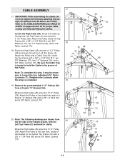
... Top Frame with a 3/8" x 2 3/4" Bolt (81), two 3/8" Washers (75), two 1/2" Spacers (34), and a 3/8" Nylon Locknut (70). Attach the Pulley and a Cable Trap (91) inside of the weight system, with the Left Top Frame (3) removed for proper cable routing and help identifying the cables. Retighten the Locknuts when this step, it may be...
... Top Frame with a 3/8" x 2 3/4" Bolt (81), two 3/8" Washers (75), two 1/2" Spacers (34), and a 3/8" Nylon Locknut (70). Attach the Pulley and a Cable Trap (91) inside of the weight system, with the Left Top Frame (3) removed for proper cable routing and help identifying the cables. Retighten the Locknuts when this step, it may be...
English Manual
Page 12
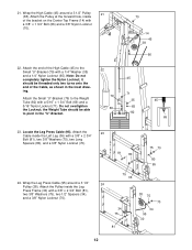
..., as shown in the "U"-Bracket. 22 79 69 70 14 45 38 66 45 71 35 65 82 45 65 23. the Weight Tube should be able to the Weight Tube (82) with a 3/8" x 2 3/4" Bolt (81), two 3/8" Washers (75), two Long Spacers (80), and a 3/8" Nylon Locknut (70). 24. Attach the Pulley inside the...
..., as shown in the "U"-Bracket. 22 79 69 70 14 45 38 66 45 71 35 65 82 45 65 23. the Weight Tube should be able to the Weight Tube (82) with a 3/8" x 2 3/4" Bolt (81), two 3/8" Washers (75), two Long Spacers (80), and a 3/8" Nylon Locknut (70). 24. Attach the Pulley inside the...
English Manual
Page 20
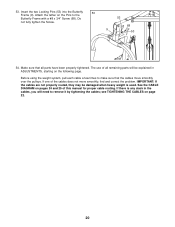
... the two Locking Pins (53) into the Butterfly 53 Frame (9). Make sure that the cables move smoothly, find and correct the problem. Before using the weight system, pull each cable a few times to the Butterfly Frame with a #8 x 3/4" Screw (68). Attach the tether on the following page. See the CABLE ... cable routing. IMPORTANT: If the cables are not properly routed, they may be explained in the cables, you will be damaged when heavy weight is any slack in ADJUSTMENTS, starting on the Pins to make sure that all remaining parts will need to remove it by tightening the cables...
... the two Locking Pins (53) into the Butterfly 53 Frame (9). Make sure that the cables move smoothly, find and correct the problem. Before using the weight system, pull each cable a few times to the Butterfly Frame with a #8 x 3/4" Screw (68). Attach the tether on the following page. See the CABLE ... cable routing. IMPORTANT: If the cables are not properly routed, they may be explained in the cables, you will be damaged when heavy weight is any slack in ADJUSTMENTS, starting on the Pins to make sure that all remaining parts will need to remove it by tightening the cables...
English Manual
Page 21
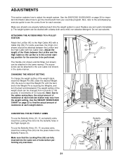
... the Lat Bar and the High Cable with two Cable Clips. ADJUSTMENTS This section explains how to find the actual amount of 12.5 pounds. The weight system can be attached to the High Cable (45) with a damp cloth and a mild, non-abrasive detergent. For some exercises, the Chain (...10, 11) as butterfly arms, insert the Locking Pins (53) into the press holes in increments of resistance at each time the weight system is touching the Weights, and turn the bent end downward. The accessories can be performed. Make sure that the Locking Pins (53) are properly tightened each ...
... the Lat Bar and the High Cable with two Cable Clips. ADJUSTMENTS This section explains how to find the actual amount of 12.5 pounds. The weight system can be attached to the High Cable (45) with a damp cloth and a mild, non-abrasive detergent. For some exercises, the Chain (...10, 11) as butterfly arms, insert the Locking Pins (53) into the press holes in increments of resistance at each time the weight system is touching the Weights, and turn the bent end downward. The accessories can be performed. Make sure that the Locking Pins (53) are properly tightened each ...
English Manual
Page 22
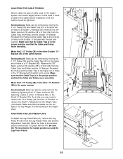
... Trap to the higher set of holes in the Double "U"-Bracket with the Bolt and Locknut. Be sure the Pin is first used on the weight system, can be removed by moving the 3 1/2" Pulley (38) and Cable Trap (91) to the locked position around the Leg Press Frame. Remove the... manner. Move the 3 1/2" Pulley (38) in the other "U"-Bracket (85) in a Double "U"-Bracket (56). See drawing B. Slack can also be removed from the Weight Tube (not shown). To do this, you may need to remove the 3 1/2" Pulley (38) from the "U"-Bracket, or remove the Small "U"-Bracket from the cables...
... Trap to the higher set of holes in the Double "U"-Bracket with the Bolt and Locknut. Be sure the Pin is first used on the weight system, can be removed by moving the 3 1/2" Pulley (38) and Cable Trap (91) to the locked position around the Leg Press Frame. Remove the... manner. Move the 3 1/2" Pulley (38) in the other "U"-Bracket (85) in a Double "U"-Bracket (56). See drawing B. Slack can also be removed from the Weight Tube (not shown). To do this, you may need to remove the 3 1/2" Pulley (38) from the "U"-Bracket, or remove the Small "U"-Bracket from the cables...
English Manual
Page 23
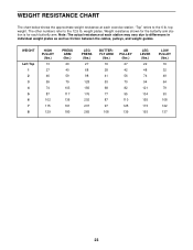
... arm station is for each station may vary due to differences in individual weight plates as well as friction between the cables, pulleys, and weight guides. WEIGHT RESISTANCE CHART The chart below shows the approximate weight resistance at each butterfly arm. weight plates. WEIGHT Left Top 1 2 3 4 5 6 7 8 HIGH PULLEY (lbs.) 13 27 46 59 74 87 102...
... arm station is for each station may vary due to differences in individual weight plates as well as friction between the cables, pulleys, and weight guides. WEIGHT RESISTANCE CHART The chart below shows the approximate weight resistance at each butterfly arm. weight plates. WEIGHT Left Top 1 2 3 4 5 6 7 8 HIGH PULLEY (lbs.) 13 27 46 59 74 87 102...
English Manual
Page 24
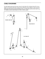
... Leg Press Cable (95), and the Leg Lever Cable (96). Make sure that the cables and the cable traps have not been correctly routed, the weight system will not function properly and damage may occur. CABLE DIAGRAMS The cable diagrams below show the correct route for each cable.
... Leg Press Cable (95), and the Leg Lever Cable (96). Make sure that the cables and the cable traps have not been correctly routed, the weight system will not function properly and damage may occur. CABLE DIAGRAMS The cable diagrams below show the correct route for each cable.
English Manual
Page 26
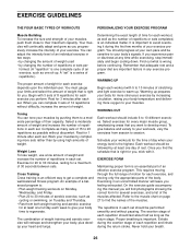
... progressively increase the intensity of your exercise program. You must gauge your body time to regenerate. Select a moderate amount of weight and increase the number of repetitions in any time while exercising, stop immediately and begin cooling down. Select exercises for you.... Exhale during the exertion stage of each exercise you will continually adapt and grow as possible without difficulty, increase the amount of weight. On the exercise guide accompanying this manual you perform. Toning You can complete 3 sets of 12 repetitions without discomfort. When you...
... progressively increase the intensity of your exercise program. You must gauge your body time to regenerate. Select a moderate amount of weight and increase the number of repetitions in any time while exercising, stop immediately and begin cooling down. Select exercises for you.... Exhale during the exertion stage of each exercise you will continually adapt and grow as possible without difficulty, increase the amount of weight. On the exercise guide accompanying this manual you perform. Toning You can complete 3 sets of 12 repetitions without discomfort. When you...
English Manual
Page 27
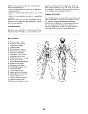
... (lower back) K T. out. • Rest for 30 seconds after each set for a toning work- list the date, the exercises performed, the weight used, and the numbers of thigh) I Q. Obliques (waist) E. Rectus Abdominus (stomach) G M. Plan to spend the first couple of weeks familiarizing ... keep a record of every month. Biceps (front of calf) K. Latissimus Dorsi (mid back) J S. Rest for each exercise. Record your weight and key body measurements at the end of each workout is to 10 minutes of time after each set . Sternomastoid (neck) B. Hip Flexors ...
... (lower back) K T. out. • Rest for 30 seconds after each set for a toning work- list the date, the exercises performed, the weight used, and the numbers of thigh) I Q. Obliques (waist) E. Rectus Abdominus (stomach) G M. Plan to spend the first couple of weeks familiarizing ... keep a record of every month. Biceps (front of calf) K. Latissimus Dorsi (mid back) J S. Rest for each exercise. Record your weight and key body measurements at the end of each workout is to 10 minutes of time after each set . Sternomastoid (neck) B. Hip Flexors ...
English Manual
Page 30
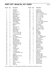
...3/4" Bolt 14 1 Center Top Frame 15 2 Backrest 16 2 Seat 17 1 Long Pad Tube 18 4 Foam Pad 19 2 Large Foam Pad 20 2 Weight Guide 21 2 Support Plate 22 7 2" x 2 1/2" Inner Cap 23 4 1 1/2" x 2" Inner Cap 24 2 1" Round Inner Cap 25 1...1" Screw 78 3 5/16" x 1" Shoulder Bolt 79 1 Small "U"-Bracket 80 2 Long Spacer 81 9 3/8" x 2 3/4" Bolt 82 1 Weight Tube 83 2 Weight Bumper 84 2 3/8" x 3 3/4" Bolt 85 2 "U"-Bracket 86 1 Weight Pin 87 1 Leg Press Pin 88 1 Adjustment Tube 89 1 5/16" x 2 1/2" Bolt 90 2 1/4" x 2 1/2" Bolt 91 6 Cable...
...3/4" Bolt 14 1 Center Top Frame 15 2 Backrest 16 2 Seat 17 1 Long Pad Tube 18 4 Foam Pad 19 2 Large Foam Pad 20 2 Weight Guide 21 2 Support Plate 22 7 2" x 2 1/2" Inner Cap 23 4 1 1/2" x 2" Inner Cap 24 2 1" Round Inner Cap 25 1...1" Screw 78 3 5/16" x 1" Shoulder Bolt 79 1 Small "U"-Bracket 80 2 Long Spacer 81 9 3/8" x 2 3/4" Bolt 82 1 Weight Tube 83 2 Weight Bumper 84 2 3/8" x 3 3/4" Bolt 85 2 "U"-Bracket 86 1 Weight Pin 87 1 Leg Press Pin 88 1 Adjustment Tube 89 1 5/16" x 2 1/2" Bolt 90 2 1/4" x 2 1/2" Bolt 91 6 Cable...
English Manual
Page 32
... Exerciser, contact the nearest Sears Service Center throughout the United States and Sears will repair or replace the Weight System Exerciser, free of charge. FULL 90 DAY WARRANTY For 90 days from state to defect in material or workmanship in Canada © 2003 Sears, ... may also have other rights which vary from the date of purchase, if failure occurs due to state. This warranty does not apply when the Weight System Exerciser is used commercially or for rental purposes.
... Exerciser, contact the nearest Sears Service Center throughout the United States and Sears will repair or replace the Weight System Exerciser, free of charge. FULL 90 DAY WARRANTY For 90 days from state to defect in material or workmanship in Canada © 2003 Sears, ... may also have other rights which vary from the date of purchase, if failure occurs due to state. This warranty does not apply when the Weight System Exerciser is used commercially or for rental purposes.


