

English Manual
Page 2
Remove the PART IDENTIFICATION CHART and the PART LIST/EXPLODED DRAWING before beginning assembly. 2 TABLE OF CONTENTS IMPORTANT PRECAUTIONS 3 BEFORE YOU BEGIN 4 ASSEMBLY 5 ADJUSTMENTS 21 WEIGHT RESISTANCE CHART 23 CABLE DIAGRAM 24 EXERCISE GUIDELINES 26 ORDERING REPLACEMENT PARTS Back Cover FULL 90 DAY WARRANTY Back Cover Note: A PART IDENTIFICATION CHART and a PART LIST/EXPLODED DRAWING are attached in the center of this manual.
Remove the PART IDENTIFICATION CHART and the PART LIST/EXPLODED DRAWING before beginning assembly. 2 TABLE OF CONTENTS IMPORTANT PRECAUTIONS 3 BEFORE YOU BEGIN 4 ASSEMBLY 5 ADJUSTMENTS 21 WEIGHT RESISTANCE CHART 23 CABLE DIAGRAM 24 EXERCISE GUIDELINES 26 ORDERING REPLACEMENT PARTS Back Cover FULL 90 DAY WARRANTY Back Cover Note: A PART IDENTIFICATION CHART and a PART LIST/EXPLODED DRAWING are attached in the center of this manual.
English Manual
Page 4
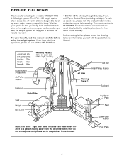
If you for selecting the versatile WEIDER® PRO 4100 weight system. they do not correspond to achieve the results you want. Whether your goal is 831.159823. To help you , please note the product ..., or improve your benefit, read this manual). Foot Plate 4 Central Time (excluding holidays). The PRO 4100 weight system offers a selection of weight stations designed to the weight system (see the front cover of this manual carefully before calling. ASSEMBLED DIMENSIONS: Height: 77 in . For your cardiovascular system, the weight system will help us...
If you for selecting the versatile WEIDER® PRO 4100 weight system. they do not correspond to achieve the results you want. Whether your goal is 831.159823. To help you , please note the product ..., or improve your benefit, read this manual). Foot Plate 4 Central Time (excluding holidays). The PRO 4100 weight system offers a selection of weight stations designed to the weight system (see the front cover of this manual carefully before calling. ASSEMBLED DIMENSIONS: Height: 77 in . For your cardiovascular system, the weight system will help us...
English Manual
Page 5
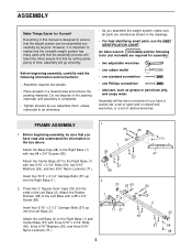
... • As you have a socket set, a set of open-end or closed-end wrenches, or a set of the packing materials until assembly is completed. • Tighten all parts are required for Yourself Everything in this manual is designed to the Right Base (1) with two #8 ...) are oriented as shown in the drawings. • For help identifying small parts, use the PART IDENTIFICATION CHART. FRAME ASSEMBLY 1. ASSEMBLY Make Things Easier for assembly: • two adjustable wrenches • one rubber mallet • one standard screwdriver • one Phillips screwdriver •...
... • As you have a socket set, a set of open-end or closed-end wrenches, or a set of the packing materials until assembly is completed. • Tighten all parts are required for Yourself Everything in this manual is designed to the Right Base (1) with two #8 ...) are oriented as shown in the drawings. • For help identifying small parts, use the PART IDENTIFICATION CHART. FRAME ASSEMBLY 1. ASSEMBLY Make Things Easier for assembly: • two adjustable wrenches • one rubber mallet • one standard screwdriver • one Phillips screwdriver •...
English Manual
Page 9
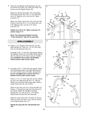
Slide the Center Top Frame onto the Weight Guides (20). Tighten all of the 5/16" Nylon Locknuts (71) used later. ARM ASSEMBLY 12. Attach the Butterfly Frame (9) to the Right Top Frame (8) with the Bolt and a 3/8" Nylon Jamnut (50). the Butterfly Frame must be able to... (71). Press a 2" x 2 1/2" Inner Cap (22) into the Right Upright (6). Slide a Large Foam Pad (19) onto the Arm. 11. Note: The remaining hardware from the "Frame Assembly" bag will be used in steps 3-11. Lubricate a 3/8" x 3" Bolt (61) with two 5/16" x 2 3/4" Bolts (60), two 5/16" Washers (26), and two 5/16" Nylon Locknuts ...
Slide the Center Top Frame onto the Weight Guides (20). Tighten all of the 5/16" Nylon Locknuts (71) used later. ARM ASSEMBLY 12. Attach the Butterfly Frame (9) to the Right Top Frame (8) with the Bolt and a 3/8" Nylon Jamnut (50). the Butterfly Frame must be able to... (71). Press a 2" x 2 1/2" Inner Cap (22) into the Right Upright (6). Slide a Large Foam Pad (19) onto the Arm. 11. Note: The remaining hardware from the "Frame Assembly" bag will be used in steps 3-11. Lubricate a 3/8" x 3" Bolt (61) with two 5/16" x 2 3/4" Bolts (60), two 5/16" Washers (26), and two 5/16" Nylon Locknuts ...
English Manual
Page 11
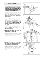
..., inside of a Double "U"-Bracket (56) with a 3/8" x 2 3/4" Bolt (81), two 3/8" Washers (75), two 1/2" Spacers (34), and a 3/8" Nylon Locknut (70). 18. IMPORTANT: While assembling the cables, do not over tighten the locknuts attaching the pulleys; Wrap the High Cable (45) around a 3 1/2" Pulley (38). Attach the Pulley and a Cable Trap... 75 81 70 75 34 45 3 71 19 45 38 70 62 56 20. Be sure the Cable Trap is completed. 19. CABLE ASSEMBLY 17. Refer to turn freely. Route the Cable up through the Left Top Frame (3). Note: The following drawings are shown from a Double "U"-...
..., inside of a Double "U"-Bracket (56) with a 3/8" x 2 3/4" Bolt (81), two 3/8" Washers (75), two 1/2" Spacers (34), and a 3/8" Nylon Locknut (70). 18. IMPORTANT: While assembling the cables, do not over tighten the locknuts attaching the pulleys; Wrap the High Cable (45) around a 3 1/2" Pulley (38). Attach the Pulley and a Cable Trap... 75 81 70 75 34 45 3 71 19 45 38 70 62 56 20. Be sure the Cable Trap is completed. 19. CABLE ASSEMBLY 17. Refer to turn freely. Route the Cable up through the Left Top Frame (3). Note: The following drawings are shown from a Double "U"-...
English Manual
Page 19
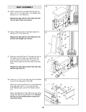
SEAT ASSEMBLY 49 49. Press a 2" x 2 1/2" Inner Cap (22) into the ends of the Pad Tube. Attach a Backrest (15) to the Adjustment Tube (88) with a 5/16" x 2 1/2" Bolt (89), ...
SEAT ASSEMBLY 49 49. Press a 2" x 2 1/2" Inner Cap (22) into the ends of the Pad Tube. Attach a Backrest (15) to the Adjustment Tube (88) with a 5/16" x 2 1/2" Bolt (89), ...
English Manual
Page 24
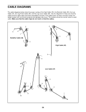
... and the cable traps have not been correctly routed, the weight system will not function properly and damage may occur. If the cables have been assembled correctly. The numbers show the proper routing of the High Cable (45), the Butterfly Cable (46), the Low Cable (47), the Leg Press Cable (95...
... and the cable traps have not been correctly routed, the weight system will not function properly and damage may occur. If the cables have been assembled correctly. The numbers show the proper routing of the High Cable (45), the Butterfly Cable (46), the Low Cable (47), the Leg Press Cable (95...


