

Uk Manual
Page 1
... Read all precautions and instructions in the space above for future reference. USER'S MANUAL Visit our website at www.iconeurope.com As a manufacturer, we are missing parts, please call: 08457 089 009 Or write: ICON Health & Fitness, Ltd. If you have questions, or if there are committed to providing complete customer satisfaction. Model No. Serial Number Decal (under seat) QUESTIONS? Save this...
... Read all precautions and instructions in the space above for future reference. USER'S MANUAL Visit our website at www.iconeurope.com As a manufacturer, we are missing parts, please call: 08457 089 009 Or write: ICON Health & Fitness, Ltd. If you have questions, or if there are committed to providing complete customer satisfaction. Model No. Serial Number Decal (under seat) QUESTIONS? Save this...

Uk Manual
Page 2
WEIDER is a registered trademark of this manual. Remove the PART IDENTIFICATION CHART and the PART LIST/EXPLODED DRAWING before beginning assembly. TABLE OF CONTENTS IMPORTANT PRECAUTIONS 3 BEFORE YOU BEGIN 4 ASSEMBLY 5 ADJUSTMENTS 15 WEIGHT RESISTANCE CHART 16 CABLE DIAGRAM 17 EXERCISE GUIDELINES 18 ORDERING REPLACEMENT PARTS Back Cover Note: A PART IDENTIFICATION CHART and a PART LIST/EXPLODED DRAWING are attached in the centre of ICON Health & Fitness, Inc. 2
WEIDER is a registered trademark of this manual. Remove the PART IDENTIFICATION CHART and the PART LIST/EXPLODED DRAWING before beginning assembly. TABLE OF CONTENTS IMPORTANT PRECAUTIONS 3 BEFORE YOU BEGIN 4 ASSEMBLY 5 ADJUSTMENTS 15 WEIGHT RESISTANCE CHART 16 CABLE DIAGRAM 17 EXERCISE GUIDELINES 18 ORDERING REPLACEMENT PARTS Back Cover Note: A PART IDENTIFICATION CHART and a PART LIST/EXPLODED DRAWING are attached in the centre of ICON Health & Fitness, Inc. 2

Uk Manual
Page 3
..., or institutional setting. 4. ICON assumes no responsibility for foot protection when using the weight system. 1. Use the weight system only as described in the locations shown on all of all instructions before using the weight system. 9. Make sure all instructions in this or any worn parts immediately. 6. Decal 1 10. Always disconnect the lat bar from the weight system when performing an exercise that the cables remain on...
..., or institutional setting. 4. ICON assumes no responsibility for foot protection when using the weight system. 1. Use the weight system only as described in the locations shown on all of all instructions before using the weight system. 9. Make sure all instructions in this or any worn parts immediately. 6. Decal 1 10. Always disconnect the lat bar from the weight system when performing an exercise that the cables remain on...

Uk Manual
Page 4
...- The weight system offers a selection of weight stations designed to the weight system (see the front cover of the body. tions, please call our Customer Service Department at 08457 089 009. Lat Bar High Pulley Station Press Arm/Butterfly Arm Front Upright ASSEMBLED DIMENSIONS: Height: 188 cm (74 in.) Width: 107 cm (42 in.) Length: 152 cm (60 in.) Warning Decal 2 (One on a decal attached to...
...- The weight system offers a selection of weight stations designed to the weight system (see the front cover of the body. tions, please call our Customer Service Department at 08457 089 009. Lat Bar High Pulley Station Press Arm/Butterfly Arm Front Upright ASSEMBLED DIMENSIONS: Height: 188 cm (74 in.) Width: 107 cm (42 in.) Length: 152 cm (60 in.) Warning Decal 2 (One on a decal attached to...

Uk Manual
Page 5
... completed. • Tighten all parts as you assemble them, unless instructed to realise that the versatile weight system has many parts and that the weight system can be assembled successfully by anyone. Do not dispose of ratchet spanners. Assembly requires the included hex key and the following information and instructions: • Assembly requires two people. • Place all parts are oriented as grease or petroleum...
... completed. • Tighten all parts as you assemble them, unless instructed to realise that the versatile weight system has many parts and that the weight system can be assembled successfully by anyone. Do not dispose of ratchet spanners. Assembly requires the included hex key and the following information and instructions: • Assembly requires two people. • Place all parts are oriented as grease or petroleum...

Uk Manual
Page 7
... Weight (30) with two M10 x 70mm Bolts (58), the 90mm Space Support Plate (21), and two M10 Nylon Locknuts (71). Press the Weight Tube Bumper (14) into the Seat Upright (73). Slide the nine Weights (7) onto the Weight 5 Guides (31). Make sure the pin on the indicated side. Do not tighten the M10 Nylon Locknuts (71) yet. 7. Attach the Seat Upright (73) to the Front Upright (6) with grease...
... Weight (30) with two M10 x 70mm Bolts (58), the 90mm Space Support Plate (21), and two M10 Nylon Locknuts (71). Press the Weight Tube Bumper (14) into the Seat Upright (73). Slide the nine Weights (7) onto the Weight 5 Guides (31). Make sure the pin on the indicated side. Do not tighten the M10 Nylon Locknuts (71) yet. 7. Attach the Seat Upright (73) to the Front Upright (6) with grease...

Uk Manual
Page 8
... Butterfly Arm (11). Don't over tighten the Locknut on the M10 x 77mm Bolt; Repeat this bolt in steps 1-8. Do not overtighten the Locknut; Press a 40mm x 50mm Inner Cap (23) into the Butterfly Frame (9). the Pivot Bracket must be attached to the Right Butterfly Arm (11) with two M8 x 15mm Allen Head Bolts (64) and two M8 Washers (62). ARM ASSEMBLY 9. Attach a Pivot...
... Butterfly Arm (11). Don't over tighten the Locknut on the M10 x 77mm Bolt; Repeat this bolt in steps 1-8. Do not overtighten the Locknut; Press a 40mm x 50mm Inner Cap (23) into the Butterfly Frame (9). the Pivot Bracket must be attached to the Right Butterfly Arm (11) with two M8 x 15mm Allen Head Bolts (64) and two M8 Washers (62). ARM ASSEMBLY 9. Attach a Pivot...

Uk Manual
Page 9
... (55) with grease. Attach the "V"-pulley and a Long Cable Trap (40) to the bracket on the Front Upright (6) with the Left Butterfly Arm (10). Repeat this step with an M10 x 57mm Bolt (69) and an M10 Nylon Locknut (71). Attach the Leg Lever (4) to the Butterfly Frame (9) with the Bolt and an M10 Nylon Locknut (71). Locate the Butterfly Cable (46). Attach the Right...
... (55) with grease. Attach the "V"-pulley and a Long Cable Trap (40) to the bracket on the Front Upright (6) with the Left Butterfly Arm (10). Repeat this step with an M10 x 57mm Bolt (69) and an M10 Nylon Locknut (71). Attach the Leg Lever (4) to the Butterfly Frame (9) with the Bolt and an M10 Nylon Locknut (71). Locate the Butterfly Cable (46). Attach the Right...

Uk Manual
Page 10
... 90mm Pulley (38). Attach the "V"-pulley and a Long Cable Trap (40) to the Double "U"-bracket (37) with an M10 x 53mm Bolt (61) and an M10 Nylon Locknut (71). Locate the High Cable (45). Route the bolt end of Pulley Covers (44) to the bracket on top. 16. Make sure the Cable Trap is turned to ... the small tabs on the Pulley Covers are on the Front Upright (6) with an M10 x 68mm Bolt (59), two M10 Washers (26), two 13mm Spacers (34), and an M10 Nylon Locknut (71). 19. Wrap the High Cable (45) over a "V"-pulley 16 (39). Attach the Pulley inside the Top Frame with an...
... 90mm Pulley (38). Attach the "V"-pulley and a Long Cable Trap (40) to the Double "U"-bracket (37) with an M10 x 53mm Bolt (61) and an M10 Nylon Locknut (71). Locate the High Cable (45). Route the bolt end of Pulley Covers (44) to the bracket on top. 16. Make sure the Cable Trap is turned to ... the small tabs on the Pulley Covers are on the Front Upright (6) with an M10 x 68mm Bolt (59), two M10 Washers (26), two 13mm Spacers (34), and an M10 Nylon Locknut (71). 19. Wrap the High Cable (45) over a "V"-pulley 16 (39). Attach the Pulley inside the Top Frame with an...
Uk Manual
Page 11
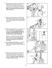
...tighten the Locknut; Attach the High Cable (45) to the Double "U"-bracket (37) with an M10 x 53mm Bolt (61) and an M10 Nylon Locknut (71). Make sure that the small tabs on the Pulley Covers are on top. 21. Locate the Short Cable (83). Attach the Pulley and a pair of holes from the indicated M10 x 77mm Bolt (60). Remove... Wrap the Short Cable (83) over a 90mm Pulley 21 (38). it should be able to pivot easily. 23 23. Attach the Pulley and a pair of Pulley Covers (44) to the second set of Pulley Covers (44) to the "U"-bracket (77) 22 with an M10 x 68mm Bolt (59), two ...
...tighten the Locknut; Attach the High Cable (45) to the Double "U"-bracket (37) with an M10 x 53mm Bolt (61) and an M10 Nylon Locknut (71). Make sure that the small tabs on the Pulley Covers are on top. 21. Locate the Short Cable (83). Attach the Pulley and a pair of holes from the indicated M10 x 77mm Bolt (60). Remove... Wrap the Short Cable (83) over a 90mm Pulley 21 (38). it should be able to pivot easily. 23 23. Attach the Pulley and a pair of Pulley Covers (44) to the second set of Pulley Covers (44) to the "U"-bracket (77) 22 with an M10 x 68mm Bolt (59), two ...

Uk Manual
Page 12
... Locate the Low Cable (47). Wrap the Cable under a 90mm Pulley (38). Wrap the Low Cable (47) over a 90mm Pulley 28 (38). Attach the Short Cable (83) to the second set of holes from the bottom of Pulley Covers (44) inside the indicated bracket on the Front Base (1) with an M10 x 53mm Bolt (61) and an M10 Nylon Locknut (71). Attach 27 the Pulley...
... Locate the Low Cable (47). Wrap the Cable under a 90mm Pulley (38). Wrap the Low Cable (47) over a 90mm Pulley 28 (38). Attach the Short Cable (83) to the second set of holes from the bottom of Pulley Covers (44) inside the indicated bracket on the Front Base (1) with an M10 x 53mm Bolt (61) and an M10 Nylon Locknut (71). Attach 27 the Pulley...

Uk Manual
Page 13
...the Low Cable (47) over a 90mm Pulley 30 (38). Route the Low Cable (47) through the Seat Upright (73) and under a 90mm Pulley (38). See the inset drawing. Make sure the small tabs on the Pulley Covers are on the bottom. Attach the Pulley and a pair of Pulley Covers (44) to the Seat Frame (5) with an M6 x 65mm Screw (65), ...two M6 x 15mm Screws (66). 32 71 26 51 44 38 4 47 70 63 33 Wide End 44 47 Small Tab 16 73 51 26 59 5 35 66 65 13 SEAT ASSEMBLY 33. Attach the Pulley and a pair of Pulley Covers (44) inside the Front Upright (6) with an M10 x 53mm Bolt (61) and an...
...the Low Cable (47) over a 90mm Pulley 30 (38). Route the Low Cable (47) through the Seat Upright (73) and under a 90mm Pulley (38). See the inset drawing. Make sure the small tabs on the Pulley Covers are on the bottom. Attach the Pulley and a pair of Pulley Covers (44) to the Seat Frame (5) with an M6 x 65mm Screw (65), ...two M6 x 15mm Screws (66). 32 71 26 51 44 38 4 47 70 63 33 Wide End 44 47 Small Tab 16 73 51 26 59 5 35 66 65 13 SEAT ASSEMBLY 33. Attach the Pulley and a pair of Pulley Covers (44) inside the Front Upright (6) with an M10 x 53mm Bolt (61) and an...

Uk Manual
Page 14
... Pad Tube (17) and the Seat Upright (73). 36. Attach the tether on page 16. 14 The use of the cables does not move smoothly over the pulleys. If one of all parts have been properly tightened. see TIGHTENING THE CABLES on the Pins to remove it by tightening the cables; Make sure that the cables move smoothly, find and correct the problem. Press two 19mm Round Inner Caps...
... Pad Tube (17) and the Seat Upright (73). 36. Attach the tether on page 16. 14 The use of the cables does not move smoothly over the pulleys. If one of all parts have been properly tightened. see TIGHTENING THE CABLES on the Pins to remove it by tightening the cables; Make sure that the cables move smoothly, find and correct the problem. Press two 19mm Round Inner Caps...

Uk Manual
Page 15
...) as press arms, insert the Locking Pins (53) into the butterfly holes in the Front Upright (6). Make sure to 13 the cables and pulleys, the actual amount of resistance at each exercise station may vary from the weight setting. Note: Due to insert the Weight Pin until the bent end of the Weight Pin is used. Make sure that the Lat Bar is in the correct starting position...
...) as press arms, insert the Locking Pins (53) into the butterfly holes in the Front Upright (6). Make sure to 13 the cables and pulleys, the actual amount of resistance at each exercise station may vary from the weight setting. Note: Due to insert the Weight Pin until the bent end of the Weight Pin is used. Make sure that the Lat Bar is in the correct starting position...

Uk Manual
Page 16
... between the cables, pulleys, and weight guides. Remove the Lock (79) and Locking Bar (80) to the 6 lb. The other numbers refer to the centre of cable used on the weight system, can be tightened. If there is slack in the cables before resistance is for each station may vary due to a set of the Weight Guides (31) and secure the Locking Bar with the Bolt and Nylon...
... between the cables, pulleys, and weight guides. Remove the Lock (79) and Locking Bar (80) to the 6 lb. The other numbers refer to the centre of cable used on the weight system, can be tightened. If there is slack in the cables before resistance is for each station may vary due to a set of the Weight Guides (31) and secure the Locking Bar with the Bolt and Nylon...

Uk Manual
Page 18
... a complete and well-balanced fitness program. Schedule your workouts for each exercise you , stick with 5 to 10 minutes of 30 seconds between sets. On the exercise guide accompanying this manual you can tone your muscles by pushing them close to their capacity. EXERCISE GUIDELINES THE FOUR BASIC TYPES OF WORKOUTS PERSONALIZING YOUR EXERCISE PROGRAM Muscle Building To increase the size and strength of your...
... a complete and well-balanced fitness program. Schedule your workouts for each exercise you , stick with 5 to 10 minutes of 30 seconds between sets. On the exercise guide accompanying this manual you can tone your muscles by pushing them close to their capacity. EXERCISE GUIDELINES THE FOUR BASIC TYPES OF WORKOUTS PERSONALIZING YOUR EXERCISE PROGRAM Muscle Building To increase the size and strength of your...

Uk Manual
Page 19
... without strain. list the date, the exercises performed, the weight used, and the numbers of arm) D. Biceps (front of sets and repetitions completed. Hip Flexors (upper thigh) G. Anterior Deltoid (shoulder) M. Posterior Deltoid (shoulder) R. Gastrocnemius (back of calf) K. Remember, the key to achieving the greatest results is an effective way to make exercise a regular and enjoyable part of your arms and legs. Adductor...
... without strain. list the date, the exercises performed, the weight used, and the numbers of arm) D. Biceps (front of sets and repetitions completed. Hip Flexors (upper thigh) G. Anterior Deltoid (shoulder) M. Posterior Deltoid (shoulder) R. Gastrocnemius (back of calf) K. Remember, the key to achieving the greatest results is an effective way to make exercise a regular and enjoyable part of your arms and legs. Adductor...

Uk Manual
Page 20
... information when ordering replacement parts: • the MODEL NUMBER of the product (WEEVSY10230) • the NAME of the product (WEIDER® 8970 weight system) • the SERIAL NUMBER of the product (see the front cover of this manual) • the KEY NUMBER and DESCRIPTION of the part(s) (see the PART LIST and EXPLODED DRAWING in the centre of this manual) Part No. 201405 R1003A Printed in China © 2003 ICON Health & Fitness...
... information when ordering replacement parts: • the MODEL NUMBER of the product (WEEVSY10230) • the NAME of the product (WEIDER® 8970 weight system) • the SERIAL NUMBER of the product (see the front cover of this manual) • the KEY NUMBER and DESCRIPTION of the part(s) (see the PART LIST and EXPLODED DRAWING in the centre of this manual) Part No. 201405 R1003A Printed in China © 2003 ICON Health & Fitness...

Uk Manual
Page 21
... help you begin each stage to the key number of the part from the PART LIST in parenthesis below each stage is divided into four stages: 1) frame assembly, 2) arm assembly, 3) cable assembly, and 4) seat assembly. Wait until you identify the small parts used in assembly. The number in the centre of this manual. Note: Assembly is packaged separately. The hardware for each part refers to open the parts bag for shipping.
... help you begin each stage to the key number of the part from the PART LIST in parenthesis below each stage is divided into four stages: 1) frame assembly, 2) arm assembly, 3) cable assembly, and 4) seat assembly. Wait until you identify the small parts used in assembly. The number in the centre of this manual. Note: Assembly is packaged separately. The hardware for each part refers to open the parts bag for shipping.

Uk Manual
Page 22
... Nylon Locknut 72 7 M4 x 20mm Screw 73 1 Seat Upright 74 1 Foot Plate 75 7 M5 Washer 76 2 Foam Grip 77 1 "U"-bracket 78 2 19mm Spacer 79 1 Lock 80 1 Locking Bar 81 1 M10 x 65mm Bolt 82 1 Large "U"-bracket 83 1 Short Cable # 1 User's Manual # 1 Exercise Guide # 1 Grease Packet # 1 Hex Key Note: "#" indicates a non-illustrated part. PART LIST-Model No. Description Key No. Specifications are subject to change without notice. WEEVSY10230 R1003A Key No. Qty.
... Nylon Locknut 72 7 M4 x 20mm Screw 73 1 Seat Upright 74 1 Foot Plate 75 7 M5 Washer 76 2 Foam Grip 77 1 "U"-bracket 78 2 19mm Spacer 79 1 Lock 80 1 Locking Bar 81 1 M10 x 65mm Bolt 82 1 Large "U"-bracket 83 1 Short Cable # 1 User's Manual # 1 Exercise Guide # 1 Grease Packet # 1 Hex Key Note: "#" indicates a non-illustrated part. PART LIST-Model No. Description Key No. Specifications are subject to change without notice. WEEVSY10230 R1003A Key No. Qty.


