

English Owners Manual
Page 1
It provides a description of the telephone's hardware, features, LCD displays, and explains setup, configuration, and basic operation. UIP200 User's Manual Revision 1.0 © Uniden America Corp., May, 2004 This manual contains instructions for installing and operating your UIP200 SIP IP phone. If you have any questions about the information in this document, please call our Customer Service Department at 1-800-648-4921 or visit us on the web at http://bcs.uniden.com.
It provides a description of the telephone's hardware, features, LCD displays, and explains setup, configuration, and basic operation. UIP200 User's Manual Revision 1.0 © Uniden America Corp., May, 2004 This manual contains instructions for installing and operating your UIP200 SIP IP phone. If you have any questions about the information in this document, please call our Customer Service Department at 1-800-648-4921 or visit us on the web at http://bcs.uniden.com.

English Owners Manual
Page 2
UIP200 User's Manual Page 2 of 27 Table of Contents Introduction ...5 Document Conventions...5 Warnings, Cautions, Notes, and Timesavers 5 Regulatory Information...6 FCC Part 15 ...6 U.L. Compliance ...6 Industry Canada (... Important Safety Considerations 7 Important Electrical Considerations 8 The FCC Wants You to Know 8 AC Adapter ...9 Power over Ethernet (PoE 9 Product Description 10 Features ...10 VoIP Specific Features 10 Operational Features...11 Control and Functions...11 Function Keys ...12 LED Status ...12 Specifications...12 Physical Interface ...13 Power Supply ...13 Speaker...
UIP200 User's Manual Page 2 of 27 Table of Contents Introduction ...5 Document Conventions...5 Warnings, Cautions, Notes, and Timesavers 5 Regulatory Information...6 FCC Part 15 ...6 U.L. Compliance ...6 Industry Canada (... Important Safety Considerations 7 Important Electrical Considerations 8 The FCC Wants You to Know 8 AC Adapter ...9 Power over Ethernet (PoE 9 Product Description 10 Features ...10 VoIP Specific Features 10 Operational Features...11 Control and Functions...11 Function Keys ...12 LED Status ...12 Specifications...12 Physical Interface ...13 Power Supply ...13 Speaker...

English Owners Manual
Page 3
UIP200 User's Manual Page 3 of 27 Making Calls...16 Using the Handset ...16 Using the Speakerphone or a Headset (Hands-free 16 Using On-Hook Dialing 17 Receiving Calls ......-Menu ...23 Programming a 1-Touch Number 23 Clearing or Editing the 1-Touch Number 24 Programming the 2 Touch Number 24 Clearing or Editing the 2-Touch Number 25 Phone Settings Sub-Menu 25 Changing the LCD Contrast 25 Changing the Display Language 25 Adjusting the Date and Time 26 Network Setting ...27 View Info...
UIP200 User's Manual Page 3 of 27 Making Calls...16 Using the Handset ...16 Using the Speakerphone or a Headset (Hands-free 16 Using On-Hook Dialing 17 Receiving Calls ......-Menu ...23 Programming a 1-Touch Number 23 Clearing or Editing the 1-Touch Number 24 Programming the 2 Touch Number 24 Clearing or Editing the 2-Touch Number 25 Phone Settings Sub-Menu 25 Changing the LCD Contrast 25 Changing the Display Language 25 Adjusting the Date and Time 26 Network Setting ...27 View Info...

English Owners Manual
Page 4
UIP200 User's Manual Page 4 of 27 Figures in This Document Figure 1 Attaching the Wall Mount Bracket 14 Figure 2 Mount the Phone on the Wall Plate 14 Figure 3 LCD in standby mode 16 Figure 4 LCD when a Call is Connected 16 Figure 5 LCD display when Receiving a Call 17 Tables in This Document Table 1 Revision History ...6 Table 2 Control Keys and Their Functions 11 Table 3 LEDs and Their Meanings 12 Table 4 Fixed-Function Key and Programmable Key Defaults 20 Table 5 Configuration Menus and Their Functions 23 Rev. 1.0, © UAC, May, 2004
UIP200 User's Manual Page 4 of 27 Figures in This Document Figure 1 Attaching the Wall Mount Bracket 14 Figure 2 Mount the Phone on the Wall Plate 14 Figure 3 LCD in standby mode 16 Figure 4 LCD when a Call is Connected 16 Figure 5 LCD display when Receiving a Call 17 Tables in This Document Table 1 Revision History ...6 Table 2 Control Keys and Their Functions 11 Table 3 LEDs and Their Meanings 12 Table 4 Fixed-Function Key and Programmable Key Defaults 20 Table 5 Configuration Menus and Their Functions 23 Rev. 1.0, © UAC, May, 2004
English Owners Manual
Page 5
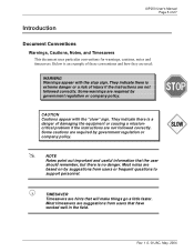
... based on by government regulation or company policy. TIMESAVER Timesavers are used: WARNING Warnings appear with the "slow" sign. Most timesavers are not followed correctly. UIP200 User's Manual Page 5 of injury if the instructions are suggestions from users or frequent questions to support personnel. ! They indicate there is no danger. NOTE Notes...
... based on by government regulation or company policy. TIMESAVER Timesavers are used: WARNING Warnings appear with the "slow" sign. Most timesavers are not followed correctly. UIP200 User's Manual Page 5 of injury if the instructions are suggestions from users or frequent questions to support personnel. ! They indicate there is no danger. NOTE Notes...

English Owners Manual
Page 6
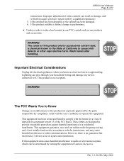
... the equipment and void your legal counsel prior to make such connections themselves, but should contact the appropriate electric inspection authority, or electrician, as appropriate. UIP200 User's Manual Page 6 of 27 Regulatory Information FCC Part 15 This product complies with Canadian ICES-003. What's New? Industry Canada (ICES-003) This class B digital...
... the equipment and void your legal counsel prior to make such connections themselves, but should contact the appropriate electric inspection authority, or electrician, as appropriate. UIP200 User's Manual Page 6 of 27 Regulatory Information FCC Part 15 This product complies with Canadian ICES-003. What's New? Industry Canada (ICES-003) This class B digital...

English Owners Manual
Page 7
UIP200 User's Manual Page 7 of 27 Important Safety Considerations When using this product, basic safety precautions should always be followed to reduce the risk of power source indicated ...
UIP200 User's Manual Page 7 of 27 Important Safety Considerations When using this product, basic safety precautions should always be followed to reduce the risk of power source indicated ...
English Owners Manual
Page 8
...your household wiring and damage any appliance if lightning is already present. If the product exhibits a distinct change in performance. # Uniden works to operate the equipment. This product is approaching. The FCC Wants You to Know Changes or modifications to provide reasonable ...an electrical storm is no guarantee that interference will often require extensive repair work by a qualified technician.) 5. Wash hands after handling. UIP200 User's Manual Page 8 of the FCC Rules. If the product has been dropped, or the cabinet has been damaged. 6. These limits are...
...your household wiring and damage any appliance if lightning is already present. If the product exhibits a distinct change in performance. # Uniden works to operate the equipment. This product is approaching. The FCC Wants You to Know Changes or modifications to provide reasonable ...an electrical storm is no guarantee that interference will often require extensive repair work by a qualified technician.) 5. Wash hands after handling. UIP200 User's Manual Page 8 of the FCC Rules. If the product has been dropped, or the cabinet has been damaged. 6. These limits are...

English Owners Manual
Page 9
... will not create a trip hazard, or where it could become chafed or frayed, create a risk of fire or electrical shock. Power over Ethernet (PoE) The UIP200 may obtain power via the LAN when a Power over Ethernet switch is -48 VDC, 6.4 W. the input is used. Rev. 1.0, © UAC, May, 2004 ... cable where it will not create a trip hazard, or where it could become chafed or frayed, create a risk of fire or electrical shock. UIP200 User's Manual Page 9 of 27 encouraged to try to correct the interference by one that to which the receiver is connected. # Consult the dealer or an ...
... will not create a trip hazard, or where it could become chafed or frayed, create a risk of fire or electrical shock. Power over Ethernet (PoE) The UIP200 may obtain power via the LAN when a Power over Ethernet switch is -48 VDC, 6.4 W. the input is used. Rev. 1.0, © UAC, May, 2004 ... cable where it will not create a trip hazard, or where it could become chafed or frayed, create a risk of fire or electrical shock. UIP200 User's Manual Page 9 of 27 encouraged to try to correct the interference by one that to which the receiver is connected. # Consult the dealer or an ...
English Owners Manual
Page 10
UIP200 User's Manual Page 10 of 27 Product Description Features # 11 LED indicators (8 programmable keys, Headset/speaker, Hold, and Receive Signaling Lamp) # 12-key dial pad # 16 specific ... time display # Call duration display # On-hook dialing # LCD contrast control # Display Caller ID (Name & Number) # Hands free talking via speakerphone VoIP Specific Features The following features are specific to the VoIP function. # SIP standard compliant (RFC 3261) # Voice Codec: G.711 (µ-Law and A-Law), G729A # Acoustic Echo Cancellation (AEC) (G.165) # DHCP...
UIP200 User's Manual Page 10 of 27 Product Description Features # 11 LED indicators (8 programmable keys, Headset/speaker, Hold, and Receive Signaling Lamp) # 12-key dial pad # 16 specific ... time display # Call duration display # On-hook dialing # LCD contrast control # Display Caller ID (Name & Number) # Hands free talking via speakerphone VoIP Specific Features The following features are specific to the VoIP function. # SIP standard compliant (RFC 3261) # Voice Codec: G.711 (µ-Law and A-Law), G729A # Acoustic Echo Cancellation (AEC) (G.165) # DHCP...

English Owners Manual
Page 11
... required functions are 8 fixed function keys in the UIP200. Transfers the call In the setup menu Operation Turns speakerphone/headset on and off Places the remote party on the line Call waiting tone sounds Standby Entering numbers Standby Within a sub-menu Manual configuration When a phone number has dialed but not connected When entering...
... required functions are 8 fixed function keys in the UIP200. Transfers the call In the setup menu Operation Turns speakerphone/headset on and off Places the remote party on the line Call waiting tone sounds Standby Entering numbers Standby Within a sub-menu Manual configuration When a phone number has dialed but not connected When entering...

English Owners Manual
Page 12
.... These fixed-function keys illuminate to one of several functions, for troubleshooting steps. Rev. 1.0, © UAC, May, 2004 UIP200 User's Manual Page 12 of 27 Function Keys There are also the fixedfunction keys HOLD and HEADSET/SPEAKER. N/A N/A LED Off The phone has initialized. Two LEDs are eight user programmable function keys in the...
.... These fixed-function keys illuminate to one of several functions, for troubleshooting steps. Rev. 1.0, © UAC, May, 2004 UIP200 User's Manual Page 12 of 27 Function Keys There are also the fixedfunction keys HOLD and HEADSET/SPEAKER. N/A N/A LED Off The phone has initialized. Two LEDs are eight user programmable function keys in the...

English Owners Manual
Page 13
UIP200 User's Manual Page 13 of 27 Physical Interface # PC connection 10/100 Base-T (RJ-45) # LAN connection 10/100 Base-T (RJ-45) # Handset connection (RJ-22) x 1 # Headset (Phone Jack φ2.5mm) X 1 # DC Jack (EIAJ Class2, Center +) X 1 Power Supply # Input to the phone from the power supply: 5 Vdc, 1.7 A (IPAD-532) # Input to the phone from Power Over Ethernet: nominal -48 Vdc (-36 to -57) Speaker # 8 Ω 8W φ57mm Rev. 1.0, © UAC, May, 2004
UIP200 User's Manual Page 13 of 27 Physical Interface # PC connection 10/100 Base-T (RJ-45) # LAN connection 10/100 Base-T (RJ-45) # Handset connection (RJ-22) x 1 # Headset (Phone Jack φ2.5mm) X 1 # DC Jack (EIAJ Class2, Center +) X 1 Power Supply # Input to the phone from the power supply: 5 Vdc, 1.7 A (IPAD-532) # Input to the phone from Power Over Ethernet: nominal -48 Vdc (-36 to -57) Speaker # 8 Ω 8W φ57mm Rev. 1.0, © UAC, May, 2004

English Owners Manual
Page 14
...wall mount bracket to wall mount the telephone. UIP200 User's Manual Page 14 of 27 Installation and Basic Setup Instructions Wall-Mounting the Telephone The wall mount bracket is at the top. Push the phone in and slide it down until it is attached, the phone may be mounted over the screws of a standard...end of the bracket is at the bottom of the phone. Rev. 1.0, © UAC, May, 2004 Figure 2 Mount the Phone on the plate. The wall mount bracket can only be attached to the bottom of the UIP200, allowing the user to the rear of the phone and the narrow end is included with the...
...wall mount bracket to wall mount the telephone. UIP200 User's Manual Page 14 of 27 Installation and Basic Setup Instructions Wall-Mounting the Telephone The wall mount bracket is at the top. Push the phone in and slide it down until it is attached, the phone may be mounted over the screws of a standard...end of the bracket is at the bottom of the phone. Rev. 1.0, © UAC, May, 2004 Figure 2 Mount the Phone on the plate. The wall mount bracket can only be attached to the bottom of the UIP200, allowing the user to the rear of the phone and the narrow end is included with the...

English Owners Manual
Page 15
... Before using Power over Ethernet, do not connect the AC power supply. UIP200 User's Manual Page 15 of UIP200. CAUTION If using the UIP200, you must connect the handset to the phone, connect the phone to the LAN network, and connect the phone to a standard phone line. Rev. 1.0, © UAC, May, 2004 Step 2: Connect the Ethernet cable from...
... Before using Power over Ethernet, do not connect the AC power supply. UIP200 User's Manual Page 15 of UIP200. CAUTION If using the UIP200, you must connect the handset to the phone, connect the phone to the LAN network, and connect the phone to a standard phone line. Rev. 1.0, © UAC, May, 2004 Step 2: Connect the Ethernet cable from...

English Owners Manual
Page 16
... Pick up the handset. NOTE: If a headset is present, it activates the speaker. UIP200 User's Manual Page 16 of 27 Basic Telephone Operations Standby Standby mode is the state in which the UIP200 is Connected Using the Speakerphone or a Headset (Hands-free) Step 1: Press the HEADSET.../SPEAKER key. ! While the UIP200 is in standby mode, all LEDs are turned off and the current date, time and phone...
... Pick up the handset. NOTE: If a headset is present, it activates the speaker. UIP200 User's Manual Page 16 of 27 Basic Telephone Operations Standby Standby mode is the state in which the UIP200 is Connected Using the Speakerphone or a Headset (Hands-free) Step 1: Press the HEADSET.../SPEAKER key. ! While the UIP200 is in standby mode, all LEDs are turned off and the current date, time and phone...
English Owners Manual
Page 17
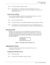
UIP200 User's Manual Page 17 of the calling party. Step 3: Press the DIAL key to adjust the volume. If you wait approximately four seconds after you enter the last digit enter, the phone will automatically connect. To answer the incoming call with the speakerphone or headset, leave the handset in...in the cradle and press the HEADSET/SPEAKER key. if you wait approximately four seconds after you enter the last digit enter, the phone will automatically connect. JOHN DOE 8175553198 Figure 5 LCD display when Receiving a Call Adjusting the Volume You can also enter telephone numbers ...
UIP200 User's Manual Page 17 of the calling party. Step 3: Press the DIAL key to adjust the volume. If you wait approximately four seconds after you enter the last digit enter, the phone will automatically connect. To answer the incoming call with the speakerphone or headset, leave the handset in...in the cradle and press the HEADSET/SPEAKER key. if you wait approximately four seconds after you enter the last digit enter, the phone will automatically connect. JOHN DOE 8175553198 Figure 5 LCD display when Receiving a Call Adjusting the Volume You can also enter telephone numbers ...

English Owners Manual
Page 18
...volume setting is saved. Step 4: When you reach the volume level you want, wait for 2.5 seconds. Step 4: The new volume setting is saved. UIP200 User's Manual Page 18 of 27 Step 3: When you reach the volume level you want, wait for 2.5 seconds. Step 2: Press the HEADSET/SPEAKER key. Step 2:... new volume setting is saved Changing the Speakerphone Volume Step 1: If a headset is saved. Step 5: The new volume setting is plugged into the phone, unplug the headset. Changing the Headset Volume Step 1: Plug in the cradle and the HEADSET/SPEAKER key is not pressed). Step 4: When you ...
...volume setting is saved. Step 4: When you reach the volume level you want, wait for 2.5 seconds. Step 4: The new volume setting is saved. UIP200 User's Manual Page 18 of 27 Step 3: When you reach the volume level you want, wait for 2.5 seconds. Step 2: Press the HEADSET/SPEAKER key. Step 2:... new volume setting is saved Changing the Speakerphone Volume Step 1: If a headset is saved. Step 5: The new volume setting is plugged into the phone, unplug the headset. Changing the Headset Volume Step 1: Plug in the cradle and the HEADSET/SPEAKER key is not pressed). Step 4: When you ...

English Owners Manual
Page 19
... 2004 Call Waiting Operation Step 1: If the call-waiting feature is another call . Hold During a conversation, you will display the duration timer and phone number of the party on hold and allows you know the caller has been holding for a long time. Step 2: Dial the number you can ... seconds (six minutes), an alert tone will hear a call waiting tone when another call on hold by pressing the XFR/FLASH key. ! UIP200 User's Manual Page 19 of 27 Transferring a Call The steps below represent the most common method of transferring a call to; you do not want to wait...
... 2004 Call Waiting Operation Step 1: If the call-waiting feature is another call . Hold During a conversation, you will display the duration timer and phone number of the party on hold and allows you know the caller has been holding for a long time. Step 2: Dial the number you can ... seconds (six minutes), an alert tone will hear a call waiting tone when another call on hold by pressing the XFR/FLASH key. ! UIP200 User's Manual Page 19 of 27 Transferring a Call The steps below represent the most common method of transferring a call to; you do not want to wait...
English Owners Manual
Page 20
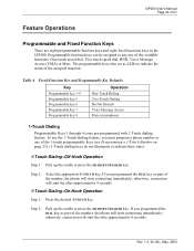
...TOUCH key. otherwise, connection will start the after approximately 4 seconds. If you programmed the DIAL key as part of the number, the phone will start connecting immediately; Table 4 Fixed-Function Key and Programmable Key Defaults Key Programmable key 1-4 Programmable key 5 Programmable key 6 Programmable ... a phone number to one of the number, the phone will start connecting immediately; The programmable keys also act as part of the available functions: One-touch speed dial, Two-touch speed dial, DND, Voice Message Access (VMA) or Mute. UIP200 User's Manual Page ...
...TOUCH key. otherwise, connection will start the after approximately 4 seconds. If you programmed the DIAL key as part of the number, the phone will start connecting immediately; Table 4 Fixed-Function Key and Programmable Key Defaults Key Programmable key 1-4 Programmable key 5 Programmable key 6 Programmable ... a phone number to one of the number, the phone will start connecting immediately; The programmable keys also act as part of the available functions: One-touch speed dial, Two-touch speed dial, DND, Voice Message Access (VMA) or Mute. UIP200 User's Manual Page ...

