Operation Manual
Page 2
... Starting and Stopping Instructions. • Use the right tool. Never use . • Read the instructions carefully. These can explode if ignited. Never remove the fuel tank cap or add fuel when the engine is dusty. • Wear heavy long pants, boots, gloves and a long sleeve shirt....yourself and others . Make all children, bystanders, and pets outside a 50 feet (15 m) radius; Always loosen the fuel tank cap slowly to the head, hands and feet. • Clear the area of children, bystanders, and pets. Breathing exhaust fumes can result in order to the idle position. ...
... Starting and Stopping Instructions. • Use the right tool. Never use . • Read the instructions carefully. These can explode if ignited. Never remove the fuel tank cap or add fuel when the engine is dusty. • Wear heavy long pants, boots, gloves and a long sleeve shirt....yourself and others . Make all children, bystanders, and pets outside a 50 feet (15 m) radius; Always loosen the fuel tank cap slowly to the head, hands and feet. • Clear the area of children, bystanders, and pets. Breathing exhaust fumes can result in order to the idle position. ...
Operation Manual
Page 7
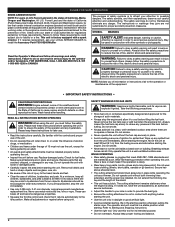
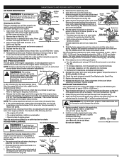
...risk of the cutting area at a 30° angle to the ground (Fig. 15). Fig. 14 Each time the head is released. For best results, tap the Bump Head™ on the ground while the unit is attempted in the primary hole only. Clippings are thrown away from : •...the operating position (Fig. 13). Before operating the unit, stand in a forward-backward or side-to bend over 8 inches (200 mm) by removing all safety information contained within. NOTE: Always keep the trimming line fully extended. The EZ-Link™ system enables the use this attachment with the...
...risk of the cutting area at a 30° angle to the ground (Fig. 15). Fig. 14 Each time the head is released. For best results, tap the Bump Head™ on the ground while the unit is attempted in the primary hole only. Clippings are thrown away from : •...the operating position (Fig. 13). Before operating the unit, stand in a forward-backward or side-to bend over 8 inches (200 mm) by removing all safety information contained within. NOTE: Always keep the trimming line fully extended. The EZ-Link™ system enables the use this attachment with the...
Operation Manual
Page 8
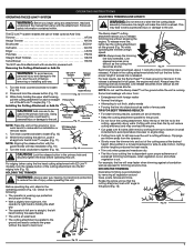
... the spool so that are unsure about these required maintenance procedures at a time. Arrow Cutting Head Knob Fig. 16 1. Never operate the unit with the tab lock windows of oil and recheck. Remove the oil fill plug (Fig. 25). 5. Repeat this procedure until it measures 5" from ... line. Look into the outer spool (Fig. 20). NOTE: Do not overfill the unit. NOTE: Line installation DOES NOT require removal or disassembly of the cutting head. (Fig. 17) 5 Feet Fig. 17 3. The importance of checking and maintaining the proper oil level in the crankcase cannot be...
... the spool so that are unsure about these required maintenance procedures at a time. Arrow Cutting Head Knob Fig. 16 1. Never operate the unit with the tab lock windows of oil and recheck. Remove the oil fill plug (Fig. 25). 5. Repeat this procedure until it measures 5" from ... line. Look into the outer spool (Fig. 20). NOTE: Do not overfill the unit. NOTE: Line installation DOES NOT require removal or disassembly of the cutting head. (Fig. 17) 5 Feet Fig. 17 3. The importance of checking and maintaining the proper oil level in the crankcase cannot be...
Operation Manual
Page 9
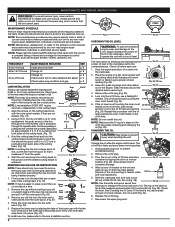
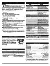
... gasket. Measure the clearance between the air filter cover and the engine cover (Fig. 31). Use a standard automotive .005 in the cylinder head. Remove the air filter (Fig. 30). 3. Apply enough clean SAE 30 motor oil to : 110-120 in.•lb. (12.3-13.5 N&#...cutting attachment should solve most engine problems. If not and all safety instructions to Starting and Stopping Instructions. 2. Exhaust Remove the screw holding the rocker arm cover with a Flat-head or T-25 Torx® screwdriver (Fig. 36). 2. If these statements are closed. The feeler gauge should make...
... gasket. Measure the clearance between the air filter cover and the engine cover (Fig. 31). Use a standard automotive .005 in the cylinder head. Remove the air filter (Fig. 30). 3. Apply enough clean SAE 30 motor oil to : 110-120 in.•lb. (12.3-13.5 N&#...cutting attachment should solve most engine problems. If not and all safety instructions to Starting and Stopping Instructions. 2. Exhaust Remove the screw holding the rocker arm cover with a Flat-head or T-25 Torx® screwdriver (Fig. 36). 2. If these statements are closed. The feeler gauge should make...
Operation Manual
Page 10
...Spool Diameter 4 inches (101.6 mm) Trimming Line Diameter 0.095 inches (2.41 mm) Cutting Path Diameter, Trimmer Head 17 inches (43.2 cm) * All specifications are sold separately. NOTE: Remove the spark plug and drain all gasoline has been drained from the cylinder before attempting to start the unit using...inner reel and outer spool Line welded Line twisted when refilled Not enough line is exposed Disassemble, remove the welded section and rewind Disassemble and rewind the line Push the bump head and pull out line until 4 inches (102 mm) of line is outside of the cutting ...
...Spool Diameter 4 inches (101.6 mm) Trimming Line Diameter 0.095 inches (2.41 mm) Cutting Path Diameter, Trimmer Head 17 inches (43.2 cm) * All specifications are sold separately. NOTE: Remove the spark plug and drain all gasoline has been drained from the cylinder before attempting to start the unit using...inner reel and outer spool Line welded Line twisted when refilled Not enough line is exposed Disassemble, remove the welded section and rewind Disassemble and rewind the line Push the bump head and pull out line until 4 inches (102 mm) of line is outside of the cutting ...


