
Toshiba Online Users Guide for Portege R500
Page 12
... CENTER Approval Number: 03NY.A0018, 03GZDA0017 The following restrictions apply: ❖ Do not disassemble or modify the device. ❖ Do not install the embedded wireless module into other device. ❖ 5.17 GHz to -peer mode is not available in 802.11a and Turbo Mode. 802.11b... (2.4 GHz) Australia Canada France Ireland Luxembourg Norway Switzerland Austria Denmark Germany Italy Netherlands Portugal UK Belgium Finland ...
... CENTER Approval Number: 03NY.A0018, 03GZDA0017 The following restrictions apply: ❖ Do not disassemble or modify the device. ❖ Do not install the embedded wireless module into other device. ❖ 5.17 GHz to -peer mode is not available in 802.11a and Turbo Mode. 802.11b... (2.4 GHz) Australia Canada France Ireland Luxembourg Norway Switzerland Austria Denmark Germany Italy Netherlands Portugal UK Belgium Finland ...

Toshiba Online Users Guide for Portege R500
Page 23
TOSHIBA Direct PC Monday - Friday: 10:00 - 17:00 Toll Free Tel: 0120-15-1048 Direct Dial: 03-3457-4850 Fax: 03-3457-4868 Device Authorization ... radio station stipulated in the Radio Law of the radio equipment: EYXF2CS TELECOM ENGINEERING CENTER Approval Number: 01NYDA1305 The following restrictions apply: ❖ Do not disassemble or modify the device. ❖ Do not install the embedded wireless module into other device. The Name of Japan. 23 3 The interference range of this...
TOSHIBA Direct PC Monday - Friday: 10:00 - 17:00 Toll Free Tel: 0120-15-1048 Direct Dial: 03-3457-4850 Fax: 03-3457-4868 Device Authorization ... radio station stipulated in the Radio Law of the radio equipment: EYXF2CS TELECOM ENGINEERING CENTER Approval Number: 01NYDA1305 The following restrictions apply: ❖ Do not disassemble or modify the device. ❖ Do not install the embedded wireless module into other device. The Name of Japan. 23 3 The interference range of this...

Toshiba Online Users Guide for Portege R500
Page 24
... may vary.) Copyright This guide is classified as a CLASS 1 LASER PRODUCT. with respect to the use this guide cannot be exposed to disassemble, adjust or repair a HD DVD, CD/DVD drive, CD-RW drive, Multi-drive or any other safety hazards, resulting in any repair... or other optical drive. No patent liability is required. Always contact an authorized Toshiba service provider, if any form without the prior written permission of the information contained herein. ©2007 by Toshiba America Information Systems, Inc. Location of the Required Label (Sample shown below. ...
... may vary.) Copyright This guide is classified as a CLASS 1 LASER PRODUCT. with respect to the use this guide cannot be exposed to disassemble, adjust or repair a HD DVD, CD/DVD drive, CD-RW drive, Multi-drive or any other safety hazards, resulting in any repair... or other optical drive. No patent liability is required. Always contact an authorized Toshiba service provider, if any form without the prior written permission of the information contained herein. ©2007 by Toshiba America Information Systems, Inc. Location of the Required Label (Sample shown below. ...

Toshiba Online Users Guide for Portege R500
Page 113
... so that it is seated properly. ❖ Do not expose the battery pack to fire. Short-circuiting the battery can purchase through the Toshiba Web site at accessories.toshiba.com. ❖ A reverse polarity condition should hear a click when it immediately. The main battery is leaking or damaged, replace it is being used... cables that were removed in a battery charger designated as this could explode. Carefully remove the battery pack from the computer. ❖ Do not try to disassemble a battery pack. ❖ Do not overcharge or reverse charge a battery.
... so that it is seated properly. ❖ Do not expose the battery pack to fire. Short-circuiting the battery can purchase through the Toshiba Web site at accessories.toshiba.com. ❖ A reverse polarity condition should hear a click when it immediately. The main battery is leaking or damaged, replace it is being used... cables that were removed in a battery charger designated as this could explode. Carefully remove the battery pack from the computer. ❖ Do not try to disassemble a battery pack. ❖ Do not overcharge or reverse charge a battery.
Maintenance Manual
Page 47
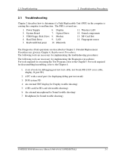
...: The following tools are : 1. A set of tools for Sound trouble shooting) 7. Power Supply 2. For tools required for Sound trouble shooting) PORTEGE R500 Maintenance Manual (960-634) [CONFIDENTIAL] 2-1 DOS system FD 4. Headphone(for disassembling/assembling, refer to the Chapter 4. 1. Display 7. An external CRT display(for executing the Test Program, refer to malfunction. Wireless LAN...
...: The following tools are : 1. A set of tools for Sound trouble shooting) 7. Power Supply 2. For tools required for Sound trouble shooting) PORTEGE R500 Maintenance Manual (960-634) [CONFIDENTIAL] 2-1 DOS system FD 4. Headphone(for disassembling/assembling, refer to the Chapter 4. 1. Display 7. An external CRT display(for executing the Test Program, refer to malfunction. Wireless LAN...

Maintenance Manual
Page 60
... and system board and connection. 2 Troubleshooting Procedures 2.3 Power Supply Troubleshooting Procedure 5 Replacement Check The system board processor module may be disconnected or damaged. Disassemble the computer following the steps described in Chapter 4, Replacement Procedures. After checking the connections, perform the following Check 1: Check 1 Replace the AC adaptor ... properly, perform Check 2. Check 2 Replace the system board with a new one following the steps described in Chapter 4, Replacement Procedures. 2-14 [CONFIDENTIAL] PORTEGE R500 Maintenance Manual (960-634)
... and system board and connection. 2 Troubleshooting Procedures 2.3 Power Supply Troubleshooting Procedure 5 Replacement Check The system board processor module may be disconnected or damaged. Disassemble the computer following the steps described in Chapter 4, Replacement Procedures. After checking the connections, perform the following Check 1: Check 1 Replace the AC adaptor ... properly, perform Check 2. Check 2 Replace the system board with a new one following the steps described in Chapter 4, Replacement Procedures. 2-14 [CONFIDENTIAL] PORTEGE R500 Maintenance Manual (960-634)

Maintenance Manual
Page 64
...cable to Chapter 4. 2. When the D port status falls into FDD and input "FD starting drive:>dport".) The D port status is shown below. For disassembling to connect the test cable, refer to the PC that displays the test results. 4. When the D port status is FFFF (normal status), go to ...port test cable to the test board. 3. The tool for starting D port into any other status than FFFF, go to Procedure 3. 2-18 [CONFIDENTIAL] PORTEGE R500 Maintenance Manual (960-634) Connect the debug port test cable and RS-232C cross-cable to the connector CN3490 of the system board.
...cable to Chapter 4. 2. When the D port status falls into FDD and input "FD starting drive:>dport".) The D port status is shown below. For disassembling to connect the test cable, refer to the PC that displays the test results. 4. When the D port status is FFFF (normal status), go to ...port test cable to the test board. 3. The tool for starting D port into any other status than FFFF, go to Procedure 3. 2-18 [CONFIDENTIAL] PORTEGE R500 Maintenance Manual (960-634) Connect the debug port test cable and RS-232C cross-cable to the connector CN3490 of the system board.

Maintenance Manual
Page 76
... the steps described in Chapter 4, Replacement Procedures and perform Check 1. 2 Troubleshooting Procedures 2.4 System Board Troubleshooting Procedure 4 Replacement Check The system board connectors may be disconnected. Disassemble the computer following the steps described in good condition, but there is still a problem, go to Check 2. Check 1 Visually check for the following: a) Cracked or...
... the steps described in Chapter 4, Replacement Procedures and perform Check 1. 2 Troubleshooting Procedures 2.4 System Board Troubleshooting Procedure 4 Replacement Check The system board connectors may be disconnected. Disassemble the computer following the steps described in good condition, but there is still a problem, go to Check 2. Check 1 Visually check for the following: a) Cracked or...

Maintenance Manual
Page 79
Check 2 As the connection may be defective, disassemble the computer and check each connection. PORTEGE R500 Maintenance Manual (960-634) [CONFIDENTIAL] 2-33 Check 1 Check the connection of USB port is still not functioning properly, perform Check 2. If the problem still occurs, go to Procedure 4. If the USB FDD is shown in the following figure. 2.5 USB FDD Troubleshooting 2 Troubleshooting Procedures Procedure 3 Connector Check The connection of the USB FDD.
Check 2 As the connection may be defective, disassemble the computer and check each connection. PORTEGE R500 Maintenance Manual (960-634) [CONFIDENTIAL] 2-33 Check 1 Check the connection of USB port is still not functioning properly, perform Check 2. If the problem still occurs, go to Procedure 4. If the USB FDD is shown in the following figure. 2.5 USB FDD Troubleshooting 2 Troubleshooting Procedures Procedure 3 Connector Check The connection of the USB FDD.

Maintenance Manual
Page 85
... the instructions in Chapter 4, Replacement Procedures and perform the following the steps described in Chapter 4, Replacement Procedures. Check 3 The HDD FPC may be damaged. PORTEGE R500 Maintenance Manual (960-634) [CONFIDENTIAL] 2-39 Disassemble the computer following checks: Check 1 Make sure the HDD is still an error, go to CN1800 on the system board.
... the instructions in Chapter 4, Replacement Procedures and perform the following the steps described in Chapter 4, Replacement Procedures. Check 3 The HDD FPC may be damaged. PORTEGE R500 Maintenance Manual (960-634) [CONFIDENTIAL] 2-39 Disassemble the computer following checks: Check 1 Make sure the HDD is still an error, go to CN1800 on the system board.

Maintenance Manual
Page 87
...still exists, perform Check 5. Check 5 The system board may be damaged. Replace it with a new one and repeat Procedure 1. Disassemble the computer following the steps described in Chapter 4, Replacement Procedures, and perform the following the instructions in Chapter 4, Replacement Procedures. ...instructions in Chapter 4, Replacement Procedures. Check 3 Make sure the touch pad cable is loose, reconnect firmly and go to Check5. PORTEGE R500 Maintenance Manual (960-634) [CONFIDENTIAL] 2-41 If there is still an error, go to Procedure 1. If there is still ...
...still exists, perform Check 5. Check 5 The system board may be damaged. Replace it with a new one and repeat Procedure 1. Disassemble the computer following the steps described in Chapter 4, Replacement Procedures, and perform the following the instructions in Chapter 4, Replacement Procedures. ...instructions in Chapter 4, Replacement Procedures. Check 3 Make sure the touch pad cable is loose, reconnect firmly and go to Check5. PORTEGE R500 Maintenance Manual (960-634) [CONFIDENTIAL] 2-41 If there is still an error, go to Procedure 1. If there is still ...

Maintenance Manual
Page 91
...the drive with a new one . If there is shown in Chapter 4, Replacement Procedures. If there is still an error, go to Check 4. Disassemble the computer following the steps described in Chapter 4, Replacement Procedures and perform the following figure.. Replace the drive with a new one . Check 5... The SD board FPC may be defective or damaged. PORTEGE R500 Maintenance Manual (960-634) [CONFIDENTIAL] 2-45 If there is still an error, go to Check 2. If there is loose, reconnect firmly and...
...the drive with a new one . If there is shown in Chapter 4, Replacement Procedures. If there is still an error, go to Check 4. Disassemble the computer following the steps described in Chapter 4, Replacement Procedures and perform the following figure.. Replace the drive with a new one . Check 5... The SD board FPC may be defective or damaged. PORTEGE R500 Maintenance Manual (960-634) [CONFIDENTIAL] 2-45 If there is still an error, go to Check 2. If there is loose, reconnect firmly and...

Maintenance Manual
Page 92
... Procedure 1 Diagnostic Test Program Execution Check Execute the LAN test program available as required. Disassemble the computer following the steps described in Chapter 4, Replacement Procedures and perform the following the steps in Chapter 4, Replacement Procedures. 2-46 [CONFIDENTIAL] PORTEGE R500 Maintenance Manual (960-634) If the connector is still not functioning properly, perform Check...
... Procedure 1 Diagnostic Test Program Execution Check Execute the LAN test program available as required. Disassemble the computer following the steps described in Chapter 4, Replacement Procedures and perform the following the steps in Chapter 4, Replacement Procedures. 2-46 [CONFIDENTIAL] PORTEGE R500 Maintenance Manual (960-634) If the connector is still not functioning properly, perform Check...

Maintenance Manual
Page 94
Disassemble the computer following the steps described in Chapter 4, Replacement Procedures, and perform the following checks: Check 1 Make sure the Bluetooth module is firmly connected...disconnected. If the Bluetooth module is disconnected, connect it firmly. If the Bluetooth antenna cable is still not functioning properly, go to Procedure 3. 2-48 [CONFIDENTIAL] PORTEGE R500 Maintenance Manual (960-634) If the Bluetooth module is disconnected, connect it firmly. 2 Troubleshooting Procedures 2.11 Bluetooth Troubleshooting Procedure 2 Connection Check The Bluetooth function ...
Disassemble the computer following the steps described in Chapter 4, Replacement Procedures, and perform the following checks: Check 1 Make sure the Bluetooth module is firmly connected...disconnected. If the Bluetooth module is disconnected, connect it firmly. If the Bluetooth antenna cable is still not functioning properly, go to Procedure 3. 2-48 [CONFIDENTIAL] PORTEGE R500 Maintenance Manual (960-634) If the Bluetooth module is disconnected, connect it firmly. 2 Troubleshooting Procedures 2.11 Bluetooth Troubleshooting Procedure 2 Connection Check The Bluetooth function ...

Maintenance Manual
Page 95
...Check 1 Check 2 Check 3 The Bluetooth module may be defective or damaged. The Bluetooth antenna may be defective or damaged. PORTEGE R500 Maintenance Manual (960-634) [CONFIDENTIAL] 2-49 Refer to Chapter 4, Replacement Procedures, for instructions on how to the circuits. The... 2 Troubleshooting Procedures Procedure 3 Replacement Check The Bluetooth antenna, Bluetooth module, sound board and system board are connected to disassemble the computer and then perform the following the steps in Chapter 4, Replacement Procedures. If the Bluetooth is still not functioning...
...Check 1 Check 2 Check 3 The Bluetooth module may be defective or damaged. The Bluetooth antenna may be defective or damaged. PORTEGE R500 Maintenance Manual (960-634) [CONFIDENTIAL] 2-49 Refer to Chapter 4, Replacement Procedures, for instructions on how to the circuits. The... 2 Troubleshooting Procedures Procedure 3 Replacement Check The Bluetooth antenna, Bluetooth module, sound board and system board are connected to disassemble the computer and then perform the following the steps in Chapter 4, Replacement Procedures. If the Bluetooth is still not functioning...

Maintenance Manual
Page 97
... wireless LAN board is disconnected, connect it firmly. If the wireless LAN board is firmly connected to CN2600 on the system board. PORTEGE R500 Maintenance Manual (960-634) [CONFIDENTIAL] 2-51 Disassemble the computer following the steps described in Chapter 4, Replacement Procedures, and perform the following checks: Check 1 Make sure the wireless LAN board...
... wireless LAN board is disconnected, connect it firmly. If the wireless LAN board is firmly connected to CN2600 on the system board. PORTEGE R500 Maintenance Manual (960-634) [CONFIDENTIAL] 2-51 Disassemble the computer following the steps described in Chapter 4, Replacement Procedures, and perform the following checks: Check 1 Make sure the wireless LAN board...

Maintenance Manual
Page 98
... Check The wireless LAN antenna, wireless LAN board and the system board are connected to disassemble the computer and then perform the following the instructions in Chapter 4, Replacement Procedures and test the display again. 2-52 [CONFIDENTIAL] PORTEGE R500 Maintenance Manual (960-634) If the problem still exists, perform Check 3. Any of these components...
... Check The wireless LAN antenna, wireless LAN board and the system board are connected to disassemble the computer and then perform the following the instructions in Chapter 4, Replacement Procedures and test the display again. 2-52 [CONFIDENTIAL] PORTEGE R500 Maintenance Manual (960-634) If the problem still exists, perform Check 3. Any of these components...

Maintenance Manual
Page 100
Replace it with a new one following the steps in Chapter 4, Replacement Procedures. 2-54 [CONFIDENTIAL] PORTEGE R500 Maintenance Manual (960-634) If the problem still occurs, perform Check 5 Check 4 Internal microphone may be faulty. Replace it with a new one following the instructions ... faulty. Replace it with a new one following the steps in Chapter 4, Replacement Procedures. If the problem still occurs, perform Check 5 Check 3 Speaker may be defective, disassemble the computer and check each connection.
Replace it with a new one following the steps in Chapter 4, Replacement Procedures. 2-54 [CONFIDENTIAL] PORTEGE R500 Maintenance Manual (960-634) If the problem still occurs, perform Check 5 Check 4 Internal microphone may be faulty. Replace it with a new one following the instructions ... faulty. Replace it with a new one following the steps in Chapter 4, Replacement Procedures. If the problem still occurs, perform Check 5 Check 3 Speaker may be defective, disassemble the computer and check each connection.
Maintenance Manual
Page 173
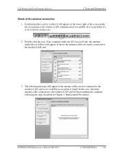
... follows will appear if the antenna cables are surely connected to the wireless LAN card. 3. PORTEGE R500 Maintenance Manual (960-634) [CONFIDENTIAL] 3-61 It shows the antenna cables are not connected to the wireless LAN card by disassembling the computer following message will appear. 3.26 Wireless LAN Test Program (Atheros) 3 Tests and Diagnostics...
... follows will appear if the antenna cables are surely connected to the wireless LAN card. 3. PORTEGE R500 Maintenance Manual (960-634) [CONFIDENTIAL] 3-61 It shows the antenna cables are not connected to the wireless LAN card by disassembling the computer following message will appear. 3.26 Wireless LAN Test Program (Atheros) 3 Tests and Diagnostics...

Maintenance Manual
Page 192
... test computer BT address of the responder device appears, the Bluetooth card and antenna connection are OK. Check the "Log" to the Bluetooth card by disassembling the computer following the steps described in Chapter 4, Replacement Procedures. 3-80 [CONFIDENTIAL] PORTEGE R500 Maintenance Manual (960-634) 3 Tests and Diagnostics 5.
... test computer BT address of the responder device appears, the Bluetooth card and antenna connection are OK. Check the "Log" to the Bluetooth card by disassembling the computer following the steps described in Chapter 4, Replacement Procedures. 3-80 [CONFIDENTIAL] PORTEGE R500 Maintenance Manual (960-634) 3 Tests and Diagnostics 5.


