
Toshiba Online Users Guide for Satellite A100/A105
Page 109
.... ❖ Flashes amber when the main battery charge is low and it indicates that the system is time to confuse the battery light ( ), the on replacing the main battery. Disconnect the AC power cord/cable and remove the battery pack. When the on/off light ( ), and the power button light (near... the upper left corner of the keyboard. NOTE If the AC power light flashes amber during charging, either the battery pack is malfunctioning, or it is not plugged into the computer or...
.... ❖ Flashes amber when the main battery charge is low and it indicates that the system is time to confuse the battery light ( ), the on replacing the main battery. Disconnect the AC power cord/cable and remove the battery pack. When the on/off light ( ), and the power button light (near... the upper left corner of the keyboard. NOTE If the AC power light flashes amber during charging, either the battery pack is malfunctioning, or it is not plugged into the computer or...

Maintenance Manual
Page 5
Keyboard scan/character codes ? Wiring diagrams ? Handling the LCD module ? Appendices The appendices describe the following parts: Chapter 1 Hardware Overview describes the Satellite A100/A105 / TECRA A7 system unit and each FRU. Key layout ? BIOS Rewrite Procedures Satellite A100/A105 / TECRA A7 Maintenance Manual v The manual is divided into the following : ? Chapter 4 Replacement Procedures describes the removal...
Keyboard scan/character codes ? Wiring diagrams ? Handling the LCD module ? Appendices The appendices describe the following parts: Chapter 1 Hardware Overview describes the Satellite A100/A105 / TECRA A7 system unit and each FRU. Key layout ? BIOS Rewrite Procedures Satellite A100/A105 / TECRA A7 Maintenance Manual v The manual is divided into the following : ? Chapter 4 Replacement Procedures describes the removal...
Maintenance Manual
Page 9
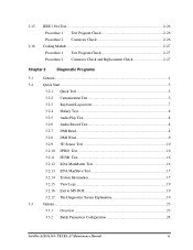
...26 Procedure 2 Connector Check 2-26 2.16 Cooling Module...2-27 Procedure 1 Test Program Check 2-27 Procedure 2 Connector Check and Replacement Check 2-27 Chapter 3 Diagnostic Programs 3.1 General ...1 3.2 Quick Start...3 3.2.1 Quick Test 3 3.2.2 Customization Test 3 3.2.3 Keyboard Layout test 7 3.2.4 Hotkey Test 8 3.2.5 Audio Play Test 8 3.2.6 Audio Record Test 8 3.2.7 DMI Read 8 3.2.8 ...19 3.2.17 The Diagnostics Screen Explanation 19 3.3 Options ...23 3.3.1 Overview 23 3.3.2 Batch Parameters Configuration 24 Satellite A100/A105 / TECRA A7 Maintenance Manual ix
...26 Procedure 2 Connector Check 2-26 2.16 Cooling Module...2-27 Procedure 1 Test Program Check 2-27 Procedure 2 Connector Check and Replacement Check 2-27 Chapter 3 Diagnostic Programs 3.1 General ...1 3.2 Quick Start...3 3.2.1 Quick Test 3 3.2.2 Customization Test 3 3.2.3 Keyboard Layout test 7 3.2.4 Hotkey Test 8 3.2.5 Audio Play Test 8 3.2.6 Audio Record Test 8 3.2.7 DMI Read 8 3.2.8 ...19 3.2.17 The Diagnostics Screen Explanation 19 3.3 Options ...23 3.3.1 Overview 23 3.3.2 Batch Parameters Configuration 24 Satellite A100/A105 / TECRA A7 Maintenance Manual ix
Maintenance Manual
Page 11
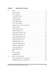
Chapter 4 Replacement Procedures 4.1 General ...4-1 Safety Precautions 4-2 Before You Begin 4-4 Disassembly Procedures 4-5 Assembly Procedures 4-5 Tools and Equipment 4-6 Screw Tightening Torque 4-6 Colors of Screw Shanks 4-7 Symbols of Screws on ... Memory 4-18 Removing the MDC Card 4-19 Installing the MDC Card 4-21 4.2 HDD...4-22 Removing the HDD 4-22 Installing the HDD 4-24 4.3 Speaker Cover and Keyboard 4-24 Removing the Speaker Cover and Keyboard 4-25 Installing the Speaker Cover and Keyboard 4-26 Satellite A100/A105 / TECRA A7 Maintenance Manual xi
Chapter 4 Replacement Procedures 4.1 General ...4-1 Safety Precautions 4-2 Before You Begin 4-4 Disassembly Procedures 4-5 Assembly Procedures 4-5 Tools and Equipment 4-6 Screw Tightening Torque 4-6 Colors of Screw Shanks 4-7 Symbols of Screws on ... Memory 4-18 Removing the MDC Card 4-19 Installing the MDC Card 4-21 4.2 HDD...4-22 Removing the HDD 4-22 Installing the HDD 4-24 4.3 Speaker Cover and Keyboard 4-24 Removing the Speaker Cover and Keyboard 4-25 Installing the Speaker Cover and Keyboard 4-26 Satellite A100/A105 / TECRA A7 Maintenance Manual xi

Maintenance Manual
Page 41
... Procedure 3Format Check 2-14 Procedure 4Test Program Check 2-15 Procedure 5Connector Check and Replacement Check 2-16 2.6 Keyboard ...2-17 Procedure 1 Test Program Check 2-17 Procedure 2 Connector Check and Replacement Check 2-17 2.7 Display...2-18 Procedure 1External Monitor Check 2-18 Procedure 2Test Program Check... Check and Replacement Check 2-20 2.9 LAN ...2-22 Procedure 1Test Program Check 2-22 Procedure 2Connector Check and Replacement Check 2-22 2.10 SD/MS/MS pro/MMC/XD Card(Optional 2-23 Procedure 1Test Program Check 2-23 2-ii Satellite A100/A105 / TECRA ...
... Procedure 3Format Check 2-14 Procedure 4Test Program Check 2-15 Procedure 5Connector Check and Replacement Check 2-16 2.6 Keyboard ...2-17 Procedure 1 Test Program Check 2-17 Procedure 2 Connector Check and Replacement Check 2-17 2.7 Display...2-18 Procedure 1External Monitor Check 2-18 Procedure 2Test Program Check... Check and Replacement Check 2-20 2.9 LAN ...2-22 Procedure 1Test Program Check 2-22 Procedure 2Connector Check and Replacement Check 2-22 2.10 SD/MS/MS pro/MMC/XD Card(Optional 2-23 Procedure 1Test Program Check 2-23 2-ii Satellite A100/A105 / TECRA ...
Maintenance Manual
Page 44
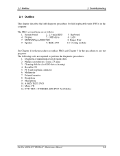
... disk kit (for field replaceable units (FRUs) in the computer. Multimeter 7. A-BEX TEST DVD 11. DVD TSD-1 (TOSHIBA EMI DVD Test Media) Satellite A100/A105 / TECRA A7 Maintenance Manual... 2-1 SD/MS/MS pro/MMC/XD 9. Speaker 9. Diagnostics (maintenance test program) disk 2. Phillips screwdrivers (2 mm, 2.5 mm) 3. PC Card loopback connector 6. Headphone 9. Music CD 12. Microphone 10. Display 5. Cooling module See Chapter 4 for the procedures to replace FRUs and Chapter 3 for the procedures to perform the diagnostic procedures: 1. Keyboard...
... disk kit (for field replaceable units (FRUs) in the computer. Multimeter 7. A-BEX TEST DVD 11. DVD TSD-1 (TOSHIBA EMI DVD Test Media) Satellite A100/A105 / TECRA A7 Maintenance Manual... 2-1 SD/MS/MS pro/MMC/XD 9. Speaker 9. Diagnostics (maintenance test program) disk 2. Phillips screwdrivers (2 mm, 2.5 mm) 3. PC Card loopback connector 6. Headphone 9. Music CD 12. Microphone 10. Display 5. Cooling module See Chapter 4 for the procedures to replace FRUs and Chapter 3 for the procedures to perform the diagnostic procedures: 1. Keyboard...

Maintenance Manual
Page 54
... 2 Troubleshooting Procedure 2 Test Program Check The maintenance test program contains several programs for diagnosing the system board and CPU. Keyboard test 4. Procedure 3 Replacement Check The system board, memory, or CPU may be defective. Satellite A100/A105 / TECRA A7 Maintenance Manual 2-11 Execute the following the steps described in Chapter 3. 1. ODD test 9. Memory test 3. Mouse...
... 2 Troubleshooting Procedure 2 Test Program Check The maintenance test program contains several programs for diagnosing the system board and CPU. Keyboard test 4. Procedure 3 Replacement Check The system board, memory, or CPU may be defective. Satellite A100/A105 / TECRA A7 Maintenance Manual 2-11 Execute the following the steps described in Chapter 3. 1. ODD test 9. Memory test 3. Mouse...
Maintenance Manual
Page 60
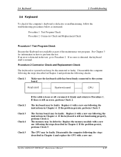
... Procedure 2. The System board may be disconnected or faulty. Satellite A100/A105 / TECRA A7 Maintenance Manual 2-17 Procedure 1 Test Program Check Procedure 2 Connector Check and Replacement Check Procedure 1 Test Program Check Execute the Keyboard test available as instructed. If no error is detected, the keyboard itself is defective or malfunctioning, follow the troubleshooting procedures below...
... Procedure 2. The System board may be disconnected or faulty. Satellite A100/A105 / TECRA A7 Maintenance Manual 2-17 Procedure 1 Test Program Check Procedure 2 Connector Check and Replacement Check Procedure 1 Test Program Check Execute the Keyboard test available as instructed. If no error is detected, the keyboard itself is defective or malfunctioning, follow the troubleshooting procedures below...

Maintenance Manual
Page 148
4 Replacement Procedures Chapter 4 Contents 4.1 General...4-1 Safety Precautions 4-2 Before You Begin 4-4 Disassembly Procedures 4-5 Assembly Procedures 4-5 Tools and Equipment 4-6 Screw Tightening Torque 4-6 Colors of Screw Shanks 4-7 Symbols of ... Memory 4-18 Removing the MDC Card 4-19 Installing the MDC Card 4-21 4.2 HDD ...4-22 Removing the HDD 4-22 Installing the HDD 4-24 4.3 Speaker Cover and Keyboard 4-24 Removing the Speaker Cover and Keyboard 4-25 Satellite A100/A105 / TECRA A7 Maintenance Manual 4-iii
4 Replacement Procedures Chapter 4 Contents 4.1 General...4-1 Safety Precautions 4-2 Before You Begin 4-4 Disassembly Procedures 4-5 Assembly Procedures 4-5 Tools and Equipment 4-6 Screw Tightening Torque 4-6 Colors of Screw Shanks 4-7 Symbols of ... Memory 4-18 Removing the MDC Card 4-19 Installing the MDC Card 4-21 4.2 HDD ...4-22 Removing the HDD 4-22 Installing the HDD 4-24 4.3 Speaker Cover and Keyboard 4-24 Removing the Speaker Cover and Keyboard 4-25 Satellite A100/A105 / TECRA A7 Maintenance Manual 4-iii

Maintenance Manual
Page 149
4 Replacement Procedures Installing the Speaker Cover and Keyboard 4-26 4.4 Bluetooth Card ...4-27 Removing the Bluetooth Card 4-27 Installing the Bluetooth Card 4-28 4.5 Wireless LAN Card 4-29 Removing the Wireless LAN Card 4-29 Installing ... VGA Card 4-45 4.11 CPU...4-46 Removing the CPU 4-46 Installing the CPU 4-47 4.12 USB Board, Finger Print Board and Print Board 4-49 4-iv Satellite A100/A105 / TECRA A7 Maintenance Manual
4 Replacement Procedures Installing the Speaker Cover and Keyboard 4-26 4.4 Bluetooth Card ...4-27 Removing the Bluetooth Card 4-27 Installing the Bluetooth Card 4-28 4.5 Wireless LAN Card 4-29 Removing the Wireless LAN Card 4-29 Installing ... VGA Card 4-45 4.11 CPU...4-46 Removing the CPU 4-46 Installing the CPU 4-47 4.12 USB Board, Finger Print Board and Print Board 4-49 4-iv Satellite A100/A105 / TECRA A7 Maintenance Manual

Maintenance Manual
Page 151
4 Replacement Procedures Figures Figure 4-1 Removing the battery pack 4-8 Figure 4-2 Removing the PCI Express card 4-10 Figure 4-3 Removing the PC card 4-12... the HDD pack 4-23 Figure 4-11 Removing the HDD cushion 4-23 Figure 4-12 Removing the speaker cover 4-25 Figure 4-13 Removing the keyboard 4-26 Figure 4-14 Removing the bluetooth card 4-27 Figure 4-15 Removing the wireless LAN card 4-29 Figure 4-16 Removing the ODD bay... Figure 4-27 Removing VGA board 4-44 Figure 4-28 Removing the CPU 4-46 Figure 4-29 Installing the CPU 4-47 4-vi Satellite A100/A105 / TECRA A7 Maintenance Manual
4 Replacement Procedures Figures Figure 4-1 Removing the battery pack 4-8 Figure 4-2 Removing the PCI Express card 4-10 Figure 4-3 Removing the PC card 4-12... the HDD pack 4-23 Figure 4-11 Removing the HDD cushion 4-23 Figure 4-12 Removing the speaker cover 4-25 Figure 4-13 Removing the keyboard 4-26 Figure 4-14 Removing the bluetooth card 4-27 Figure 4-15 Removing the wireless LAN card 4-29 Figure 4-16 Removing the ODD bay... Figure 4-27 Removing VGA board 4-44 Figure 4-28 Removing the CPU 4-46 Figure 4-29 Installing the CPU 4-47 4-vi Satellite A100/A105 / TECRA A7 Maintenance Manual

Maintenance Manual
Page 153
...keyboard, and wireless LAN card, all the surrounding FRUs to the section numbers shown in the boxes. To replace the FRUs, first identify the suspect FRU for the system failure. Some replacement... procedures may not require you determine those FRUs, go to the appropriate sections according to replace... and replacement How to disassemble the computer and replace Field Replaceable Units ...before removing the suspect FRU. 4.1 General 4 Replacement Procedures 4 1 4.1 General This chapter explains...
...keyboard, and wireless LAN card, all the surrounding FRUs to the section numbers shown in the boxes. To replace the FRUs, first identify the suspect FRU for the system failure. Some replacement... procedures may not require you determine those FRUs, go to the appropriate sections according to replace... and replacement How to disassemble the computer and replace Field Replaceable Units ...before removing the suspect FRU. 4.1 General 4 Replacement Procedures 4 1 4.1 General This chapter explains...

Maintenance Manual
Page 178
Four front latches 2. Remove the speaker cover. Figure 4-12 Removing the speaker cover 4-26 Satellite A100/A105 / TECRA A7 Maintenance Manual Release the following procedures and Figure 4-12, 4-13. 1. Six bottom latches - 4 Replacement Procedures 4.3 Speaker Cover and Keyboard 4.3 Speaker Cover and Keyboard Removing the Speaker Cover and Keyboard Remove the Speaker Cover and Keyboard according to the following 10 latches on the switch cover, in that order: -
Four front latches 2. Remove the speaker cover. Figure 4-12 Removing the speaker cover 4-26 Satellite A100/A105 / TECRA A7 Maintenance Manual Release the following procedures and Figure 4-12, 4-13. 1. Six bottom latches - 4 Replacement Procedures 4.3 Speaker Cover and Keyboard 4.3 Speaker Cover and Keyboard Removing the Speaker Cover and Keyboard Remove the Speaker Cover and Keyboard according to the following 10 latches on the switch cover, in that order: -

Maintenance Manual
Page 179
... screws. 3. Four front latches 4. Satellite A100/A105 / TECRA A7 Maintenance Manual 4-27 Remove the connector CN11 on main board and keyboard. Figure 4-13 Removing the keyboard Installing the Speaker Cover and Keyboard Install the speaker cover and keyboard according to h the main board connector CN11 and route it correctly. 2. 4.3 Speaker Cover and Keyboard 4 Replacement Procedures 3. Place the speaker...
... screws. 3. Four front latches 4. Satellite A100/A105 / TECRA A7 Maintenance Manual 4-27 Remove the connector CN11 on main board and keyboard. Figure 4-13 Removing the keyboard Installing the Speaker Cover and Keyboard Install the speaker cover and keyboard according to h the main board connector CN11 and route it correctly. 2. 4.3 Speaker Cover and Keyboard 4 Replacement Procedures 3. Place the speaker...


