Service Manual
Page 1
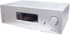
...Area code Power requirements US, Canadian AEP, UK 120 V AC, 60 Hz 230 V AC, 50 Hz 2)Reference power output for front, center, surround speakers and sub woofer. rated 85 watts per channel Surround mode2) (reference) (6 ohms 100 Hz, THD 10%) SUB WOOFER: 135 W 1)Measured under license...STEREO/FM-AM RECEIVER 9-887-542-02 2007C16-1 © 2007.03 Sony Corporation Home Audio Division Published by Sony Techno Create Corporation SERVICE MANUAL Ver. 1.1 2007.03 STR-K790 US Model Canadian Model AEP Model UK Model • STR-K790 is the tuner and the amplifier section in any AM station, turn...
...Area code Power requirements US, Canadian AEP, UK 120 V AC, 60 Hz 230 V AC, 50 Hz 2)Reference power output for front, center, surround speakers and sub woofer. rated 85 watts per channel Surround mode2) (reference) (6 ohms 100 Hz, THD 10%) SUB WOOFER: 135 W 1)Measured under license...STEREO/FM-AM RECEIVER 9-887-542-02 2007C16-1 © 2007.03 Sony Corporation Home Audio Division Published by Sony Techno Create Corporation SERVICE MANUAL Ver. 1.1 2007.03 STR-K790 US Model Canadian Model AEP Model UK Model • STR-K790 is the tuner and the amplifier section in any AM station, turn...
Service Manual
Page 3
..., HDMI BRIDGE Board (AEP, UK only 24 4-12. Schematic Diagram - Schematic Diagram - Front Panel Section 42 5-2. RL RL CENTER FRONT SPEAKERS Area code Any differences in operation, according to the area code, are clearly indicated in the text, for example, "Models of the rear ... MAIN Board (3/4 29 4-17. Schematic Diagram - Block Diagram - Printed Wiring Board - DIGITAL Board (Side B) - ...... 17 4-5. Schematic Diagram - Schematic Diagram - STR-K790 About area codes The area code of the receiver you purchased is shown on the lower right portion of area code AA only".
..., HDMI BRIDGE Board (AEP, UK only 24 4-12. Schematic Diagram - Schematic Diagram - Front Panel Section 42 5-2. RL RL CENTER FRONT SPEAKERS Area code Any differences in operation, according to the area code, are clearly indicated in the text, for example, "Models of the rear ... MAIN Board (3/4 29 4-17. Schematic Diagram - Block Diagram - Printed Wiring Board - DIGITAL Board (Side B) - ...... 17 4-5. Schematic Diagram - Schematic Diagram - STR-K790 About area codes The area code of the receiver you purchased is shown on the lower right portion of area code AA only".
Service Manual
Page 4
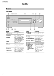
... to select 2CH STEREO mode. Turn to select the input source to activate the Sleep Timer function and the duration which the receiver turns off . STR-K790 Receiver Front panel 1 234 ?/1 VIDEO 1 IN/ PORTABLE AUDIO IN/ AUTO CAL MIC DIMMER SLEEP 2CH A.F.D. Press to playback. mode. q; 9 Name H... such as MP3 player, etc.. 4 Press to select sound fields (MOVIE, MUSIC). The current status of the selected component or a list of all speakers at the same time. M PHONES jack N VIDEO 1 IN/ PORTABLE AUDIO IN/ AUTO CAL MIC jack Function Turn to turn the receiver on /standby...
... to select 2CH STEREO mode. Turn to select the input source to activate the Sleep Timer function and the duration which the receiver turns off . STR-K790 Receiver Front panel 1 234 ?/1 VIDEO 1 IN/ PORTABLE AUDIO IN/ AUTO CAL MIC DIMMER SLEEP 2CH A.F.D. Press to playback. mode. q; 9 Name H... such as MP3 player, etc.. 4 Press to select sound fields (MOVIE, MUSIC). The current status of the selected component or a list of all speakers at the same time. M PHONES jack N VIDEO 1 IN/ PORTABLE AUDIO IN/ AUTO CAL MIC jack Function Turn to turn the receiver on /standby...
Service Manual
Page 6
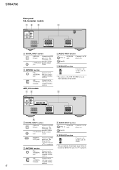
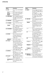
...DVD IN jack player, etc. STR-K790 Rear panel US, Canadian models 12 3 4 DIGITAL OPTICAL VIDEO 2/ BD IN COAXIAL DVD IN ANTENNA AM L R AUDIO IN AUDIO IN AUDIO IN SA-CD/CD TV SAT RL SUB RL WOOFER SURROUND SPEAKERS RL RL CENTER FRONT SPEAKERS A DIGITAL INPUT section OPTICAL Connects... R AUDIO IN AUDIO IN AUDIO IN SA-CD/CD TV SAT SUB R L WOOFER SURROUND SPEAKERS RL RL CENTER FRONT SPEAKERS 4 A DIGITAL INPUT section C AUDIO INPUT section OPTICAL Connects to the speakers and sub woofer*. * The numbers of loud jack sound. The COAXIAL jack provides a better COAXIAL...
...DVD IN jack player, etc. STR-K790 Rear panel US, Canadian models 12 3 4 DIGITAL OPTICAL VIDEO 2/ BD IN COAXIAL DVD IN ANTENNA AM L R AUDIO IN AUDIO IN AUDIO IN SA-CD/CD TV SAT RL SUB RL WOOFER SURROUND SPEAKERS RL RL CENTER FRONT SPEAKERS A DIGITAL INPUT section OPTICAL Connects... R AUDIO IN AUDIO IN AUDIO IN SA-CD/CD TV SAT SUB R L WOOFER SURROUND SPEAKERS RL RL CENTER FRONT SPEAKERS 4 A DIGITAL INPUT section C AUDIO INPUT section OPTICAL Connects to the speakers and sub woofer*. * The numbers of loud jack sound. The COAXIAL jack provides a better COAXIAL...
Service Manual
Page 8
...the VCR, CD player, DVD player or Blu-ray disc player. H* Press to activate muting function. PRESET +/- Press to select 2CH STEREO mode. STR-K790 Name Function D 2CH Press to select preset stations or preset channels of the VCR or satellite tuner. mode. and TV (O) at the same time to... perform menu operations. MASTER VOL Press to display the menu of all speakers at the same time. TUNING +/- H DVD MENU Press to adjust the volume +*/- erasing multiple titles). Press TV CH +/- Press to select FM ...
...the VCR, CD player, DVD player or Blu-ray disc player. H* Press to activate muting function. PRESET +/- Press to select 2CH STEREO mode. STR-K790 Name Function D 2CH Press to select preset stations or preset channels of the VCR or satellite tuner. mode. and TV (O) at the same time to... perform menu operations. MASTER VOL Press to display the menu of all speakers at the same time. TUNING +/- H DVD MENU Press to adjust the volume +*/- erasing multiple titles). Press TV CH +/- Press to select FM ...
Service Manual
Page 10
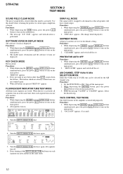
...AM CHANNEL STEP 9 kHz/10 kHz SELECTION MODE Either the 9 kHz step or 10 kHz step can be swapped to all channels so that all speakers will have sound output. Set the FUNCTION to turn on the main power. 2. Use this mode is activated. CLR." Every pressing of any button ... The signal will be selected for the AM channel step. ALL" appears. (No change while displayed.) SHIPMENT MODE All preset contents are displayed. STR-K790 SECTION 2 TEST MODE SOUND FIELD CLEAR MODE The preset sound field is cleared when this mode before returning the product to clients upon completion of...
...AM CHANNEL STEP 9 kHz/10 kHz SELECTION MODE Either the 9 kHz step or 10 kHz step can be swapped to all channels so that all speakers will have sound output. Set the FUNCTION to turn on the main power. 2. Use this mode is activated. CLR." Every pressing of any button ... The signal will be selected for the AM channel step. ALL" appears. (No change while displayed.) SHIPMENT MODE All preset contents are displayed. STR-K790 SECTION 2 TEST MODE SOUND FIELD CLEAR MODE The preset sound field is cleared when this mode before returning the product to clients upon completion of...
Service Manual
Page 11
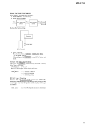
... : Press the three buttons MUSIC + DISPLAY + ?/1 . "DCAC[]FTM" appears. Turn MASTER VOLUME jog, there will be test tone sound output from front left speaker of test tone) STR-K790 11 "AD[]-[]xxx" xxx = 0 to start , below display will show: "DCAC[][][]x" x = 1, 2, 3 If there is error happen, below display will change..., press the DIMMER to 255 (depends on loudness of the receiver and AUTO CAL microphone. DCAC board Checking Connect front left speaker, and the display will show: "ERR[]SD0x" x = 1 → D1501 or R1530 x = 2 → D1502 problem x = 3 → D1503 problem...
... : Press the three buttons MUSIC + DISPLAY + ?/1 . "DCAC[]FTM" appears. Turn MASTER VOLUME jog, there will be test tone sound output from front left speaker of test tone) STR-K790 11 "AD[]-[]xxx" xxx = 0 to start , below display will show: "DCAC[][][]x" x = 1, 2, 3 If there is error happen, below display will change..., press the DIMMER to 255 (depends on loudness of the receiver and AUTO CAL microphone. DCAC board Checking Connect front left speaker, and the display will show: "ERR[]SD0x" x = 1 → D1501 or R1530 x = 2 → D1502 problem x = 3 → D1503 problem...
Service Manual
Page 15
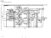
BLOCK DIAGRAM - STR-K790 • R-CH is omitted due to same as L-CH. • Signal Path : FM L IC501 POWER AMP +V OUT2 12 8 ...POWER PROTECT SR-CH Q707 AF POWER PROTECT Q608 RELAY DRIVE RY551 R-CH TM602(1/2) L R FRONT RY601 R-CH TM604(1/2) L R SURROUND Q708 RELAY DRIVE RY701 SPEAKERS IMPEDANCE USE 6-16Ω TM602(2/2) CENTER TM604(2/2) SUB WOOFER IC850 2 PROTECT DET 7 POWER AMP -B +B -B FL101 -20V TUNER +10V RELAY +B AUDIO...-913 F901 AC IN Q911 AC DET D914 D915 T900(AEP,UK) T902(US,CND) Q901 RELAY DRIVE RY901 STR-K790 15 15 DISPLAY/POWER SECTION - 4-2.
BLOCK DIAGRAM - STR-K790 • R-CH is omitted due to same as L-CH. • Signal Path : FM L IC501 POWER AMP +V OUT2 12 8 ...POWER PROTECT SR-CH Q707 AF POWER PROTECT Q608 RELAY DRIVE RY551 R-CH TM602(1/2) L R FRONT RY601 R-CH TM604(1/2) L R SURROUND Q708 RELAY DRIVE RY701 SPEAKERS IMPEDANCE USE 6-16Ω TM602(2/2) CENTER TM604(2/2) SUB WOOFER IC850 2 PROTECT DET 7 POWER AMP -B +B -B FL101 -20V TUNER +10V RELAY +B AUDIO...-913 F901 AC IN Q911 AC DET D914 D915 T900(AEP,UK) T902(US,CND) Q901 RELAY DRIVE RY901 STR-K790 15 15 DISPLAY/POWER SECTION - 4-2.
Service Manual
Page 25
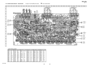
...BOARD AEP,UK JW853 CC54 C452 C402 R454 TP1 DCAC BOARD B CN2001 (7pin-9pin) (Page 33) SPEAKERS IMPEDANCE USE 6-16 SUB WOOFER SURROUND R L CNP733 RY701 AEP,UK JW829 CC16 RR16 TM604 CC15 CC14 RR15 RR14 JWH17 ...AEP,UK JW950 SPEAKERS IMPEDANCE USE 6-16 CENTER FRONT R L JW830 JWH19 JW845 TM602 JW844 RR13 CC13 CC12 RR12 JW831 CC11 RR11 ... Q754 Q755 Q756 Q801 Q851 Q852 Q881 Q882 Q883 Location G-4 G-3 C-6 G-5 H-6 H-5 H-6 G-6 G-5 F-14 F-11 E-9 E-12 F-12 F-12 STR-K790 25 25
...BOARD AEP,UK JW853 CC54 C452 C402 R454 TP1 DCAC BOARD B CN2001 (7pin-9pin) (Page 33) SPEAKERS IMPEDANCE USE 6-16 SUB WOOFER SURROUND R L CNP733 RY701 AEP,UK JW829 CC16 RR16 TM604 CC15 CC14 RR15 RR14 JWH17 ...AEP,UK JW950 SPEAKERS IMPEDANCE USE 6-16 CENTER FRONT R L JW830 JWH19 JW845 TM602 JW844 RR13 CC13 CC12 RR12 JW831 CC11 RR11 ... Q754 Q755 Q756 Q801 Q851 Q852 Q881 Q882 Q883 Location G-4 G-3 C-6 G-5 H-6 H-5 H-6 G-6 G-5 F-14 F-11 E-9 E-12 F-12 F-12 STR-K790 25 25

Service Manual
Page 29
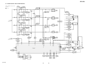
STR-K790 (Page 27) TP2 20 MAIN BOARD (1/4) (Page 27) (Page 30) POWER AMP IC701 STK350-530T-E 37 -37 37 1 -1 37 -0.2 -0.2 37 1.1 -1 37 -0.2 -0.2 R700 47k C701 4.7 50V ... 0.2 Q708 2SC1740S-QRT RELAY DRIVE 0.7 R725 100 RR14 10 CC14 0.01 RR15 10 CC15 0.01 RR16 10 CC16 0.01 TM604 R479 2.2k CNP504 5P L SURROUND R SPEAKERS IMPEDANCE USE 6-16 SUB WOOFER D DIGITAL BOARD (4/5) CNP506 (Page 21) No mark:FM STR-K790 29 29 MAIN BOARD (3/4) - SCHEMATIC DIAGRAM - 4-16.
STR-K790 (Page 27) TP2 20 MAIN BOARD (1/4) (Page 27) (Page 30) POWER AMP IC701 STK350-530T-E 37 -37 37 1 -1 37 -0.2 -0.2 37 1.1 -1 37 -0.2 -0.2 R700 47k C701 4.7 50V ... 0.2 Q708 2SC1740S-QRT RELAY DRIVE 0.7 R725 100 RR14 10 CC14 0.01 RR15 10 CC15 0.01 RR16 10 CC16 0.01 TM604 R479 2.2k CNP504 5P L SURROUND R SPEAKERS IMPEDANCE USE 6-16 SUB WOOFER D DIGITAL BOARD (4/5) CNP506 (Page 21) No mark:FM STR-K790 29 29 MAIN BOARD (3/4) - SCHEMATIC DIAGRAM - 4-16.
Service Manual
Page 30
STR-K790 Ver. 1.1 4-17. MAIN BOARD (4/4) - (Page 27) IC501 STK350-530T-E 37 POWER AMP 37 1 -1 37 -0.2 -0.2 -0.2 -0.2 37 -1 1 37 R500 47k C501 4.7 50V R501 1k C500 2.2 100V C502 ...-QRT RELAY DRIVE CN701 4P J HEADPHONE BOARD CNP790 (Page 34) TM602 RR11 10 RR12 10 RR13 10 CC11 0.01 CC12 0.01 CC13 0.01 TM602 FRONT SPEAKERS IMPEDANCE USE 6-16 CENTER No mark:FM STR-K790 30 30 SCHEMATIC DIAGRAM -
STR-K790 Ver. 1.1 4-17. MAIN BOARD (4/4) - (Page 27) IC501 STK350-530T-E 37 POWER AMP 37 1 -1 37 -0.2 -0.2 -0.2 -0.2 37 -1 1 37 R500 47k C501 4.7 50V R501 1k C500 2.2 100V C502 ...-QRT RELAY DRIVE CN701 4P J HEADPHONE BOARD CNP790 (Page 34) TM602 RR11 10 RR12 10 RR13 10 CC11 0.01 CC12 0.01 CC13 0.01 TM602 FRONT SPEAKERS IMPEDANCE USE 6-16 CENTER No mark:FM STR-K790 30 30 SCHEMATIC DIAGRAM -
Service Manual
Page 40
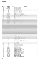
Connection for a crystal resonator 84 VCC3 - STR-K790 Pin No. Ground terminal 82 X0 - Not used ) 92 BST_SEL O BST signal output terminal 93 XMODE O Reset signal output to DIR 94 CKSEL 1 O CKSEL ...VOL_ENCODER (A) I Volume signal input from rotary encoder 66 FRONT_RY/DG51_FB O Front A speaker relay control signal output 67 FRONT_B_RY/DG51_FA O Front B speaker control signal output 68 DC-CONTROL O Center speaker relay control signal output 69 C/REAR/SB_RY O Center, rear, surround back speaker control signal output 70 SW_RY O Sub woofer control signal output 71 NC...
Connection for a crystal resonator 84 VCC3 - STR-K790 Pin No. Ground terminal 82 X0 - Not used ) 92 BST_SEL O BST signal output terminal 93 XMODE O Reset signal output to DIR 94 CKSEL 1 O CKSEL ...VOL_ENCODER (A) I Volume signal input from rotary encoder 66 FRONT_RY/DG51_FB O Front A speaker relay control signal output 67 FRONT_B_RY/DG51_FA O Front B speaker control signal output 68 DC-CONTROL O Center speaker relay control signal output 69 C/REAR/SB_RY O Center, rear, surround back speaker control signal output 70 SW_RY O Sub woofer control signal output 71 NC...
Service Manual
Page 53
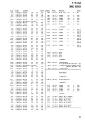
... F (AEP, UK) 1/4W F 1/4W F 1/4W 1/4W F 1/4W 1/4W 1/4W 1/4W 1/4W TM600 1-694-805-11 TERMINAL BOARD (FRONT,CENTER/SPEAKERS IMPEDANCE 6-16Ω) TM602 1-694-805-11 TERMINAL BOARD (SURROUND,SUB WOOFER/ SPEAKERS IMPEDANCE 6-16Ω) TM604 1-694-805-11 TERMINAL BOARD POWER BOARD < CONNECTOR > 1/4W F 1/4W 1/4W 1/4W F 1/4W F 1/4W 1/4W... R855 R856 R857 1-249-435-11 CARBON 1-247-887-00 CARBON 1-247-895-00 CARBON 1-249-429-11 CARBON 33K 5% 220K 5% 470K 5% 10K 5% Remark Ref. STR-K790 MAIN POWER Ref.
... F (AEP, UK) 1/4W F 1/4W F 1/4W 1/4W F 1/4W 1/4W 1/4W 1/4W 1/4W TM600 1-694-805-11 TERMINAL BOARD (FRONT,CENTER/SPEAKERS IMPEDANCE 6-16Ω) TM602 1-694-805-11 TERMINAL BOARD (SURROUND,SUB WOOFER/ SPEAKERS IMPEDANCE 6-16Ω) TM604 1-694-805-11 TERMINAL BOARD POWER BOARD < CONNECTOR > 1/4W F 1/4W 1/4W 1/4W F 1/4W F 1/4W 1/4W... R855 R856 R857 1-249-435-11 CARBON 1-247-887-00 CARBON 1-247-895-00 CARBON 1-249-429-11 CARBON 33K 5% 220K 5% 470K 5% 10K 5% Remark Ref. STR-K790 MAIN POWER Ref.


