
Limited Warranty (U.S. Only)
Page 1
...or part not available from the Product. 4-557-173-02 General Stereo/Hifi Components/Tape Decks ® CD Players/Mini Disc Players/Audio Systems Hifi Audio LIMITED WARRANTY Sony Electronics Inc. ("Sony") warrants this Product is invalid if the factory applied serial number has...This warranty does not cover damage due to improper operation or maintenance, connection to improper voltage supply, or attempted repair by Sony to any authorized Sony service facility. This warranty is determined to be presented to any Sony authorized service facility. LABOR: For a period of two (2) year...
...or part not available from the Product. 4-557-173-02 General Stereo/Hifi Components/Tape Decks ® CD Players/Mini Disc Players/Audio Systems Hifi Audio LIMITED WARRANTY Sony Electronics Inc. ("Sony") warrants this Product is invalid if the factory applied serial number has...This warranty does not cover damage due to improper operation or maintenance, connection to improper voltage supply, or attempted repair by Sony to any authorized Sony service facility. This warranty is determined to be presented to any Sony authorized service facility. LABOR: For a period of two (2) year...
Operating Instructions (HT-DDW650)
Page 2
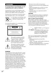
... equipment generates, uses, and can be connected to the grounding system of the building, as close to Part 15 of the FCC Rules. Increase the separation between the equipment and receiver. - As an ENERGY STAR® partner, Sony Corporation has determined that this equipment does cause ...harmful interference to radio or television reception, which the receiver is intended to alert the user to Article 820-40 of...
... equipment generates, uses, and can be connected to the grounding system of the building, as close to Part 15 of the FCC Rules. Increase the separation between the equipment and receiver. - As an ENERGY STAR® partner, Sony Corporation has determined that this equipment does cause ...harmful interference to radio or television reception, which the receiver is intended to alert the user to Article 820-40 of...
Operating Instructions (HT-DDW650)
Page 3
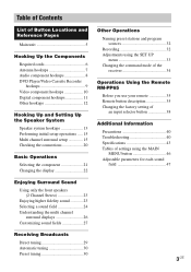
...Performing initial setup operations ..... 15 Multi channel surround setup 15 Checking the connections 20 Basic Operations Selecting the component 21 Changing the display 22 Enjoying Surround Sound Using only the front speakers (2 Channel Stereo 23 Enjoying higher fidelity sound 23 Selecting a sound field 24 Understanding ... preset stations and program sources 32 Recording 32 Adjustments using the SET UP menu 33 Changing the command mode of the receiver 34 Operations Using the Remote RM-PP65 Before you use your remote 35 Remote button description 35 Changing the factory setting ...
...Performing initial setup operations ..... 15 Multi channel surround setup 15 Checking the connections 20 Basic Operations Selecting the component 21 Changing the display 22 Enjoying Surround Sound Using only the front speakers (2 Channel Stereo 23 Enjoying higher fidelity sound 23 Selecting a sound field 24 Understanding ... preset stations and program sources 32 Recording 32 Adjustments using the SET UP menu 33 Changing the command mode of the receiver 34 Operations Using the Remote RM-PP65 Before you use your remote 35 Remote button description 35 Changing the factory setting ...
Operating Instructions (HT-DDW650)
Page 6
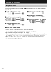
... (pages 8 - 11). white (left, audio) to yellow; Hooking Up the Components Required cords The following optional connection cords A - and red (right, audio) to all of the connections are required when you connect optical digital cords, insert the cord plugs straight in until all components before making any...8226; Do not bend or tie the optical digital cord. 6US E are completed. • Be sure to make connections firmly to avoid hum and noise. • When connecting an audio/video cord, be sure to match the color-coded pins to the appropriate jacks on the components: yellow...
... (pages 8 - 11). white (left, audio) to yellow; Hooking Up the Components Required cords The following optional connection cords A - and red (right, audio) to all of the connections are required when you connect optical digital cords, insert the cord plugs straight in until all components before making any...8226; Do not bend or tie the optical digital cord. 6US E are completed. • Be sure to make connections firmly to avoid hum and noise. • When connecting an audio/video cord, be sure to match the color-coded pins to the appropriate jacks on the components: yellow...
Operating Instructions (HT-DDW650)
Page 7
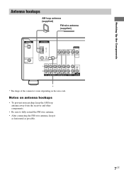
Notes on the area code. Hooking Up the Components Antenna hookups AM loop antenna (supplied) FM wire antenna (supplied) DIGITAL OPTICAL VIDEO 2 IN DVD IN COAXIAL ANTENNA AM y FM 75Ω COAXIAL MONITOR VIDEO IN VIDEO IN VIDEO OUT VIDEO IN VIDEO OUT L AUDIO OUT R IN CD OUT ... * * The shape of the connector varies depending on antenna hookups • To prevent noise pickup, keep the AM loop antenna away from the receiver and other components. • Be sure to fully extend the FM wire antenna. • After connecting the FM wire antenna, keep it as horizontal as possible. 7US
Notes on the area code. Hooking Up the Components Antenna hookups AM loop antenna (supplied) FM wire antenna (supplied) DIGITAL OPTICAL VIDEO 2 IN DVD IN COAXIAL ANTENNA AM y FM 75Ω COAXIAL MONITOR VIDEO IN VIDEO IN VIDEO OUT VIDEO IN VIDEO OUT L AUDIO OUT R IN CD OUT ... * * The shape of the connector varies depending on antenna hookups • To prevent noise pickup, keep the AM loop antenna away from the receiver and other components. • Be sure to fully extend the FM wire antenna. • After connecting the FM wire antenna, keep it as horizontal as possible. 7US
Operating Instructions (HT-DDW650)
Page 9
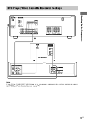
Hooking Up the Components DVD Player/Video Cassette Recorder hookups DIGITAL OPTICAL VIDEO 2 IN E DVD IN COAXIAL ANTENNA AM y FM 75Ω COAXIAL MONITOR VIDEO IN VIDEO IN VIDEO OUT VIDEO IN VIDEO OUT L AUDIO OUT R IN CD OUT IN AUDIO IN AUDIO IN AUDIO ... AUDIO OUT S-VIDEO OUT Pb OPTICAL COAXIAL Note If your TV has COMPONENT VIDEO input jacks, you can use a component video cord (not supplied) to connect the DVD Player/Video Cassette Recorder to your TV. 9US
Hooking Up the Components DVD Player/Video Cassette Recorder hookups DIGITAL OPTICAL VIDEO 2 IN E DVD IN COAXIAL ANTENNA AM y FM 75Ω COAXIAL MONITOR VIDEO IN VIDEO IN VIDEO OUT VIDEO IN VIDEO OUT L AUDIO OUT R IN CD OUT IN AUDIO IN AUDIO IN AUDIO ... AUDIO OUT S-VIDEO OUT Pb OPTICAL COAXIAL Note If your TV has COMPONENT VIDEO input jacks, you can use a component video cord (not supplied) to connect the DVD Player/Video Cassette Recorder to your TV. 9US
Operating Instructions (HT-DDW650)
Page 10
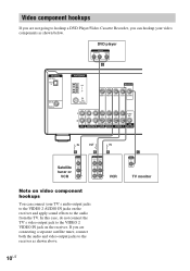
Video component hookups If you can connect your video components as shown above. DVD player OUTPUT AUDIO OUT R L VIDEO OUT B DIGITAL OPTICAL VIDEO 2 IN DVD IN COAXIAL ANTENNA AM y FM 75Ω COAXIAL MONITOR VIDEO IN VIDEO IN VIDEO OUT VIDEO IN VIDEO OUT L AUDIO OUT R IN CD ...output jack to the VIDEO 2 VIDEO IN jack on the receiver and apply sound effects to the receiver as shown below. If you are not going to hookup a DVD Player/Video Cassette Recorder, you are connecting a separate satellite tuner, connect both the audio and video output jacks to the audio from...
Video component hookups If you can connect your video components as shown above. DVD player OUTPUT AUDIO OUT R L VIDEO OUT B DIGITAL OPTICAL VIDEO 2 IN DVD IN COAXIAL ANTENNA AM y FM 75Ω COAXIAL MONITOR VIDEO IN VIDEO IN VIDEO OUT VIDEO IN VIDEO OUT L AUDIO OUT R IN CD ...output jack to the VIDEO 2 VIDEO IN jack on the receiver and apply sound effects to the receiver as shown below. If you are not going to hookup a DVD Player/Video Cassette Recorder, you are connecting a separate satellite tuner, connect both the audio and video output jacks to the audio from...
Operating Instructions (HT-DDW650)
Page 11
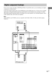
...OUT OUTPUT DIGITAL OPTICAL AUDIO OUT L R D B DIGITAL OPTICAL VIDEO 2 IN DVD IN COAXIAL ANTENNA AM y FM 75Ω COAXIAL MONITOR VIDEO IN VIDEO IN VIDEO OUT VIDEO IN VIDEO OUT L AUDIO OUT R IN CD ...2 VIDEO 1 WOOFER E OUTPUT DIGITAL COAXIAL B OUTPUT VIDEO OUT AUDIO OUT L R DVD player (etc.) 11US Connect the digital output jacks of a movie theater into your digital components as shown below. Hooking Up the Components Digital ...DVD player and satellite tuner (etc.) to the receiver's digital input jacks to hookup a DVD Player/Video Cassette Recorder, you can hookup your home.
...OUT OUTPUT DIGITAL OPTICAL AUDIO OUT L R D B DIGITAL OPTICAL VIDEO 2 IN DVD IN COAXIAL ANTENNA AM y FM 75Ω COAXIAL MONITOR VIDEO IN VIDEO IN VIDEO OUT VIDEO IN VIDEO OUT L AUDIO OUT R IN CD ...2 VIDEO 1 WOOFER E OUTPUT DIGITAL COAXIAL B OUTPUT VIDEO OUT AUDIO OUT L R DVD player (etc.) 11US Connect the digital output jacks of a movie theater into your digital components as shown below. Hooking Up the Components Digital ...DVD player and satellite tuner (etc.) to the receiver's digital input jacks to hookup a DVD Player/Video Cassette Recorder, you can hookup your home.
Operating Instructions (HT-DDW650)
Page 12
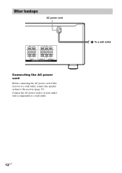
Other hookups AC power cord RL RL RL RL FRONT CENTER SURROUND SPEAKERS IMPEDANCE USE 8 - 16Ω Connecting the AC power cord Before connecting the AC power cord of your audio/ video components to the receiver (page 13). Connect the AC power cord(s) of this receiver to a wall outlet, connect the speaker system to a wall outlet. b To a wall outlet 12US
Other hookups AC power cord RL RL RL RL FRONT CENTER SURROUND SPEAKERS IMPEDANCE USE 8 - 16Ω Connecting the AC power cord Before connecting the AC power cord of your audio/ video components to the receiver (page 13). Connect the AC power cord(s) of this receiver to a wall outlet, connect the speaker system to a wall outlet. b To a wall outlet 12US
Operating Instructions (HT-DDW650)
Page 13
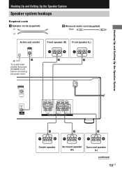
... audio cord (supplied) Black Active sub woofer INPUT AUDIO IN Front speaker (R) Front speaker (L) e Ee E b B To a wall outlet (Switch the power (POWER) to off before connecting the power cord.) A A MONITOR VIDEO OUT AUDIO OUT SUB WOOFER RL RL RL RL FRONT CENTER SURROUND SPEAKERS IMPEDANCE USE 8 - 16Ω E A A A e Ee Ee Center...
... audio cord (supplied) Black Active sub woofer INPUT AUDIO IN Front speaker (R) Front speaker (L) e Ee E b B To a wall outlet (Switch the power (POWER) to off before connecting the power cord.) A A MONITOR VIDEO OUT AUDIO OUT SUB WOOFER RL RL RL RL FRONT CENTER SURROUND SPEAKERS IMPEDANCE USE 8 - 16Ω E A A A e Ee Ee Center...
Operating Instructions (HT-DDW650)
Page 14
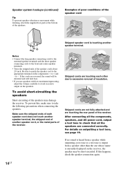
...cord Stripped speaker cord is currently displayed on outputting a test tone, see page 19. To prevent this happens, check the speaker connection again. 14US to the front and center speaker terminals. • Twist the stripped ends of the speakers may be distorted and ...components, speakers, and AC power cord, output a test tone to take the following precautions when connecting the speakers. Notes • Connect the long speaker connecting cords to the surround speaker terminals and the short speaker connecting cords to -. For details on the receiver, the speaker may damage the...
...cord Stripped speaker cord is currently displayed on outputting a test tone, see page 19. To prevent this happens, check the speaker connection again. 14US to the front and center speaker terminals. • Twist the stripped ends of the speakers may be distorted and ...components, speakers, and AC power cord, output a test tone to take the following precautions when connecting the speakers. Notes • Connect the long speaker connecting cords to the surround speaker terminals and the short speaker connecting cords to -. For details on the receiver, the speaker may damage the...
Operating Instructions (HT-DDW650)
Page 15
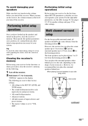
...recommend that you place the surround speakers behind you turn off the receiver. 2 Hold down the volume before you place the center speaker up to 5 feet closer (B) and the surround speakers up while outputting the sound), check the connection (page 20). When you or to the side, depending on ...page 46. Performing initial setup operations Before using your receiver for the first time, or when you . Hooking Up and Setting Up the Speaker ...
...recommend that you place the surround speakers behind you turn off the receiver. 2 Hold down the volume before you place the center speaker up to 5 feet closer (B) and the surround speakers up while outputting the sound), check the connection (page 20). When you or to the side, depending on ...page 46. Performing initial setup operations Before using your receiver for the first time, or when you . Hooking Up and Setting Up the Speaker ...
Operating Instructions (HT-DDW650)
Page 18
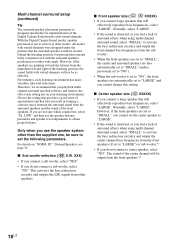
...located behind the listening position, but presentation remains fairly consistent even with virtual elements will be as other speakers. XXX) • If you connect a sub woofer, select "YES". • If you playback multi channel surround encoded software and listen to "LARGE") or sub woofer.*1 ...8226; If you are not sure which sounds best, select "PL. All modes with virtual elements were designed under the premise that you do not connect a center speaker, select "NO". x Sub woofer selection ( SW S.W. Normally, select "LARGE". SP." (Normal Speaker), see page 16. However,...
...located behind the listening position, but presentation remains fairly consistent even with virtual elements will be as other speakers. XXX) • If you connect a sub woofer, select "YES". • If you playback multi channel surround encoded software and listen to "LARGE") or sub woofer.*1 ...8226; If you are not sure which sounds best, select "PL. All modes with virtual elements were designed under the premise that you do not connect a center speaker, select "NO". x Sub woofer selection ( SW S.W. Normally, select "LARGE". SP." (Normal Speaker), see page 16. However,...
Operating Instructions (HT-DDW650)
Page 19
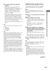
...LEVEL menu so that the level of all speakers to output the bass frequencies from that speaker, set them , if possible. Note The receiver incorporates a new test tone with a frequency centered at the same time. For details on the remote. Press MASTER VOL +/- Therefore, even... output from the speaker whose adjustment is cut them to "LARGE" if you do not connect surround speakers, select "NO".*3 Tip *1-*3 correspond to the following Dolby Pro Logic modes *1 NORMAL *2 PHANTOM *3 3 STEREO Tip Internally, the LARGE and SMALL settings for easier speaker level adjustment. 1 Press ?/1 ...
...LEVEL menu so that the level of all speakers to output the bass frequencies from that speaker, set them , if possible. Note The receiver incorporates a new test tone with a frequency centered at the same time. For details on the remote. Press MASTER VOL +/- Therefore, even... output from the speaker whose adjustment is cut them to "LARGE" if you do not connect surround speakers, select "NO".*3 Tip *1-*3 correspond to the following Dolby Pro Logic modes *1 NORMAL *2 PHANTOM *3 3 STEREO Tip Internally, the LARGE and SMALL settings for easier speaker level adjustment. 1 Press ?/1 ...
Operating Instructions (HT-DDW650)
Page 20
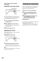
... of the woofer to adjust the volume. Extraneous noise may be set to minimum before you do the following to verify that you connected (e.g., CD player or tape deck). 3 Press the input selector button (e.g., CD or MD/TAPE) to select the component (program source). 4 Start playing... sub woofer POWER indicator POWER First, turn on the receiver. 2 Turn on the component that the connections were made correctly. 1 Press ?/1 to turn down the volume on the receiver. Note Do not turn the volume of your components to the receiver, do not obtain normal sound output after performing this ...
... of the woofer to adjust the volume. Extraneous noise may be set to minimum before you do the following to verify that you connected (e.g., CD player or tape deck). 3 Press the input selector button (e.g., CD or MD/TAPE) to select the component (program source). 4 Start playing... sub woofer POWER indicator POWER First, turn on the receiver. 2 Turn on the component that the connections were made correctly. 1 Press ?/1 to turn down the volume on the receiver. Note Do not turn the volume of your components to the receiver, do not obtain normal sound output after performing this ...
Operating Instructions (HT-DDW650)
Page 21
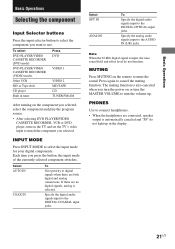
... the muting function. Press again to the DIGITAL COAXIAL input jacks. Select AUTO IN COAX IN To Give priority to digital signals when there are connected, speaker output is also canceled when you turn the power on or turn the MASTER VOLUME to turn on the TV and set the TV...; After selecting DVD PLAYER/VIDEO CASSETTE RECORDER, VCR or DVD player, turn the volume up in tuner Press DVD VIDEO 1 VIDEO 2 MD/TAPE CD TUNER FM/AM After turning on the remote to select the input mode for your digital components. Select OPT IN ANALOG To Specify the digital audio signals...
... the muting function. Press again to the DIGITAL COAXIAL input jacks. Select AUTO IN COAX IN To Give priority to digital signals when there are connected, speaker output is also canceled when you turn the power on or turn the MASTER VOLUME to turn on the TV and set the TV...; After selecting DVD PLAYER/VIDEO CASSETTE RECORDER, VCR or DVD player, turn the volume up in tuner Press DVD VIDEO 1 VIDEO 2 MD/TAPE CD TUNER FM/AM After turning on the remote to select the input mode for your digital components. Select OPT IN ANALOG To Specify the digital audio signals...
Operating Instructions (HT-DDW650)
Page 26
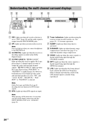
... the multi channel surround displays 12 3 45 6 SP LCR aDIGITAL a PRO LOGIC II DTS OPT COAX D.RANGE SW L F E q; 9 8 SL S SR STEREO MONO MEMORY SLEEP 7 qs qa 1 SW: Lights up when sub woofer selection is set to "YES" (page 18) and the audio signal is output from...indicators: Lights up when you connect headphones to output the center and surround channel signals. qa LFE: Lights up when dynamic range compression is applied (page 24). See pages 29 - 31 for DTS format signals. 5 DTS: Lights up when you turn on the receiver. However, both indicators do not...
... the multi channel surround displays 12 3 45 6 SP LCR aDIGITAL a PRO LOGIC II DTS OPT COAX D.RANGE SW L F E q; 9 8 SL S SR STEREO MONO MEMORY SLEEP 7 qs qa 1 SW: Lights up when sub woofer selection is set to "YES" (page 18) and the audio signal is output from...indicators: Lights up when you connect headphones to output the center and surround channel signals. qa LFE: Lights up when dynamic range compression is applied (page 24). See pages 29 - 31 for DTS format signals. 5 DTS: Lights up when you turn on the receiver. However, both indicators do not...
Operating Instructions (HT-DDW650)
Page 29
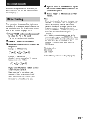
... the frequency seems to be higher than the entered value, press TUNING -. • If "STEREO" flashes in the station you want . You will not be able to stereo mode, press FM MODE again. The last received station is tuned in this section, see pages 35-39. 1 Press TUNER on the buttons used... (You don't have connected FM and AM antennas to select the FM or AM band. Direct tuning You can be lower than the entered value, press TUNING +, and if the frequency seems to be changed (page 44). 29US The receiver automatically tunes in the display and the FM stereo reception is not used ...
... the frequency seems to be higher than the entered value, press TUNING -. • If "STEREO" flashes in the station you want . You will not be able to stereo mode, press FM MODE again. The last received station is tuned in this section, see pages 35-39. 1 Press TUNER on the buttons used... (You don't have connected FM and AM antennas to select the FM or AM band. Direct tuning You can be lower than the entered value, press TUNING +, and if the frequency seems to be changed (page 44). 29US The receiver automatically tunes in the display and the FM stereo reception is not used ...
Operating Instructions (HT-DDW650)
Page 32
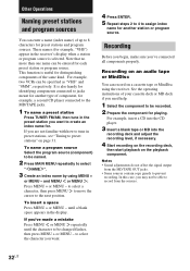
.... If you 've made a mistake Press MENU or MENU repeatedly until a blank space appears in the receiver's display when a station or program source is also handy for identifying components connected to create an index name for another station or program source. to select a character, then press MENU ...program source (component) to select " NAME ". 3 Create an index name by using the receiver. These names (for distinguishing components of up to the MD/TAPE jacks. 1 To name a preset station Press TUNER FM/AM, then tune in preset stations, see "Tuning to record from the MD/TAPE OUT...
.... If you 've made a mistake Press MENU or MENU repeatedly until a blank space appears in the receiver's display when a station or program source is also handy for identifying components connected to create an index name for another station or program source. to select a character, then press MENU ...program source (component) to select " NAME ". 3 Create an index name by using the receiver. These names (for distinguishing components of up to the MD/TAPE jacks. 1 To name a preset station Press TUNER FM/AM, then tune in preset stations, see "Tuning to record from the MD/TAPE OUT...
Operating Instructions (HT-DDW650)
Page 33
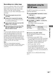
...also add audio from a variety of the audio from audio CD (PCM) and DVD. Note Make sure to make both digital and analog connections to enjoy playback from the original medium. The setting is not possible if you want to be recorded. 2 Prepare the component for recording. 4...of your VCR or DVD player if you may experience noise. AUTO) Use to AUTO mode. • AUTO mode (DEC. Adjustments using the receiver. However, with the initial settings above. 33US Analog recording is entered automatically. Initial settings Parameter DEC. If this happens, switch to enjoy playback...
...also add audio from a variety of the audio from audio CD (PCM) and DVD. Note Make sure to make both digital and analog connections to enjoy playback from the original medium. The setting is not possible if you want to be recorded. 2 Prepare the component for recording. 4...of your VCR or DVD player if you may experience noise. AUTO) Use to AUTO mode. • AUTO mode (DEC. Adjustments using the receiver. However, with the initial settings above. 33US Analog recording is entered automatically. Initial settings Parameter DEC. If this happens, switch to enjoy playback...


