
Service Manual
Page 8
... jack to a SYNC OUT lighting device. a)You can use the supplied remote RM-AAP013 to operate the receiver and to control the Sony audio/video components that the remote is assigned to the AM loop antenna supplied with this receiver . b)Except for models of area code MX, E51 . STR-K1500 F D-LIGHT SYNC OUT section D-LIGHT Connects to a TV monitor.
... jack to a SYNC OUT lighting device. a)You can use the supplied remote RM-AAP013 to operate the receiver and to control the Sony audio/video components that the remote is assigned to the AM loop antenna supplied with this receiver . b)Except for models of area code MX, E51 . STR-K1500 F D-LIGHT SYNC OUT section D-LIGHT Connects to a TV monitor.
Service Manual
Page 9
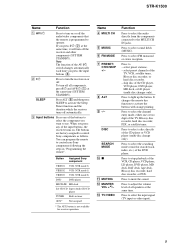
...receiver turns off automatically. select preset stations. - Press to activate the buttons with orange printing. It changes the remote key function to light up the button. C Input buttons Press one or two digit of the TV, Blu-ray disc recorder, hard disc recorder, PSX, or satellite tuner. Press to control Sony components...VCD player (multi-disc change only). STR-K1500 Name Function A AV ?/1 Press to turn on or off the audio/video components that the remote is not available for search (track, index, etc.) of the DVD player. Button Assigned Sony component VIDEO1 VCR (VTR mode 3) VIDEO2...
...receiver turns off automatically. select preset stations. - Press to activate the buttons with orange printing. It changes the remote key function to light up the button. C Input buttons Press one or two digit of the TV, Blu-ray disc recorder, hard disc recorder, PSX, or satellite tuner. Press to control Sony components...VCD player (multi-disc change only). STR-K1500 Name Function A AV ?/1 Press to turn on or off the audio/video components that the remote is not available for search (track, index, etc.) of the DVD player. Button Assigned Sony component VIDEO1 VCR (VTR mode 3) VIDEO2...

Service Manual
Page 17
... SW1 1 STB CLK DIN 789 B MAIN SECTION (Page 16) FL_DATA FL_CLK IC101 BUFFER 9 -V OUT1 3 Q110 LED DRIVE D105 Q534 BOOSTER FL_LAT SYSTEM CONTROL IC1101(2/2) X0 X1 A/D1 A/D2 ADCC STR-K1500 J2000 AUTO CAL MIC 82 83 39 40 38 X1101 24MHz FUNCTION KEY S108-111,115 FUNCTION KEY S101-107 IC2000 5 AMP... 55 62 66 69 68 67 56 58 S100 ?/1 FUSE DETECT 63 SIRCS 54 AVCC 35 VCC3 84 VCC5 23 RSTX 77 STOP 48 IC102 REMOTE 1 CONTROL RECEIVER IC1111 1 RESET 2 +3.3V +2.5V +5V TUNER +10V RELAY +B AUDIO +7V AUDIO +5V AUDIO -7V +3.3V (STBY) 17 17 Q801 -20V REG D802 R803 T901 Q691...
... SW1 1 STB CLK DIN 789 B MAIN SECTION (Page 16) FL_DATA FL_CLK IC101 BUFFER 9 -V OUT1 3 Q110 LED DRIVE D105 Q534 BOOSTER FL_LAT SYSTEM CONTROL IC1101(2/2) X0 X1 A/D1 A/D2 ADCC STR-K1500 J2000 AUTO CAL MIC 82 83 39 40 38 X1101 24MHz FUNCTION KEY S108-111,115 FUNCTION KEY S101-107 IC2000 5 AMP... 55 62 66 69 68 67 56 58 S100 ?/1 FUSE DETECT 63 SIRCS 54 AVCC 35 VCC3 84 VCC5 23 RSTX 77 STOP 48 IC102 REMOTE 1 CONTROL RECEIVER IC1111 1 RESET 2 +3.3V +2.5V +5V TUNER +10V RELAY +B AUDIO +7V AUDIO +5V AUDIO -7V +3.3V (STBY) 17 17 Q801 -20V REG D802 R803 T901 Q691...

Service Manual
Page 45
... clock output O I/O expander O/P enable output O I System reset input O Muting signal output to DIR STR-K1500 45 Not used O BST signal output terminal O Reset signal output to DIR O CKSEL control signal output to DIR O Clock signal output to DIR O Chip enable signal output to the tuner - ...RDS data signal input (Short to ground terminal) I Data signal input from the remote control sensor I Headphone signal input I Power switch key detect signal input I ADCC DSP interrept input O Power relay control signal output O Volume IC clock signal output O Volume IC data and latch ...
... clock output O I/O expander O/P enable output O I System reset input O Muting signal output to DIR STR-K1500 45 Not used O BST signal output terminal O Reset signal output to DIR O CKSEL control signal output to DIR O Clock signal output to DIR O Chip enable signal output to the tuner - ...RDS data signal input (Short to ground terminal) I Data signal input from the remote control sensor I Headphone signal input I Power switch key detect signal input I ADCC DSP interrept input O Power relay control signal output O Volume IC clock signal output O Volume IC data and latch ...


