Dimensions Diagram
Page 1
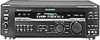
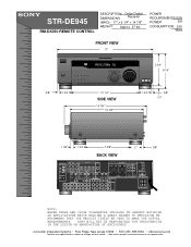
... are approximate. SONY WILL NOT BE RESPONSIBLE FOR INACCURACIES IN THE DESIGN OR MANUFACTURE OF ENCLOSURES . STR-DE945 RM-DX350 REMOTE CONTROL DESCRIPTION: Dolby Digital DIMENSIONS Receiver (WHD): 17..." x 6 1/4" x 14 7/8" WEIGHT: Approx 27 lbs POWER REQUIREMENTS:120V POWER 60H CONSUMPTION: 290 Watts FRONT VIEW 17" R FM102.7MHz A3 5 3/4" 6 1/4" 5/8" 1 3/4 " 12 1/4 " SIDE VIEW 14 7/8 " 12 7/8" 1 3/4 " 5/8" 1/2" 1 1/8" 1 3/4 " 7 3/8" BACK VIEW 2 " 5/8" ANTENNA AM. COAXIAL FM...
... are approximate. SONY WILL NOT BE RESPONSIBLE FOR INACCURACIES IN THE DESIGN OR MANUFACTURE OF ENCLOSURES . STR-DE945 RM-DX350 REMOTE CONTROL DESCRIPTION: Dolby Digital DIMENSIONS Receiver (WHD): 17..." x 6 1/4" x 14 7/8" WEIGHT: Approx 27 lbs POWER REQUIREMENTS:120V POWER 60H CONSUMPTION: 290 Watts FRONT VIEW 17" R FM102.7MHz A3 5 3/4" 6 1/4" 5/8" 1 3/4 " 12 1/4 " SIDE VIEW 14 7/8 " 12 7/8" 1 3/4 " 5/8" 1/2" 1 1/8" 1 3/4 " 7 3/8" BACK VIEW 2 " 5/8" ANTENNA AM. COAXIAL FM...
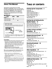
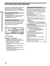
Operating Instructions
Page 1
4-229-126-12(1) FM Stereo FM-AM Receiver Operating Instructions STR-DE945 STR-DE845 © 2000 Sony Corporation
4-229-126-12(1) FM Stereo FM-AM Receiver Operating Instructions STR-DE945 STR-DE845 © 2000 Sony Corporation
Operating Instructions
Page 2
...sunlight, excessive dust or mechanical shock. • Do not place anything on the rear of the unit. STR-DE945/DE845 Serial No. As an ENERGY STAR® partner, Sony Corporation has determined that the operating voltage is intended to alert the user to the presence of important operating and...guarantee that provides guidelines for energy efficiency. To disconnect the AC power cord, grasp the plug itself has been turned off and unplug the receiver. On cleaning Clean the cabinet, panel and controls with a soft cloth slightly moistened with the limits for help. 2 CAUTION You are ...
...sunlight, excessive dust or mechanical shock. • Do not place anything on the rear of the unit. STR-DE945/DE845 Serial No. As an ENERGY STAR® partner, Sony Corporation has determined that the operating voltage is intended to alert the user to the presence of important operating and...guarantee that provides guidelines for energy efficiency. To disconnect the AC power cord, grasp the plug itself has been turned off and unplug the receiver. On cleaning Clean the cabinet, panel and controls with a soft cloth slightly moistened with the limits for help. 2 CAUTION You are ...
Operating Instructions
Page 3
...corner of area code AA only". This receiver incorporates Dolby* Digital and Pro Logic Surround and the DTS** Digital Surround System. * Manufactured under license from Dolby Laboratories. About This Manual The instructions in this manual are for example, "STR-DE945 only." Check your remote, refer to ...the area code, are clearly indicated in the text, for example, "Models of the front panel. In this manual, the STR-DE945 is used for making the task easier. R L REAR CENTER 8 - 16Ω SUB WOOFER FRONT 4 Ω 8 Ω IMPEDANCE SELECTOR AC...
...corner of area code AA only". This receiver incorporates Dolby* Digital and Pro Logic Surround and the DTS** Digital Surround System. * Manufactured under license from Dolby Laboratories. About This Manual The instructions in this manual are for example, "STR-DE945 only." Check your remote, refer to ...the area code, are clearly indicated in the text, for example, "Models of the front panel. In this manual, the STR-DE945 is used for making the task easier. R L REAR CENTER 8 - 16Ω SUB WOOFER FRONT 4 Ω 8 Ω IMPEDANCE SELECTOR AC...
Operating Instructions
Page 4
... of area code U, CA only • Audio/video/control S connecting cord (1) • Control S connecting cord (1) STR-DE945 only • Remote commander RM-LJ304 (remote) (1) STR-DE845 only • Remote commander RM-LP204 (remote) (1) Inserting batteries into the remote Insert LR6 (size-AA) alkaline ...8226; This remote is designed for use with the + and - When the remote no longer operates the receiver, replace all components before you received the following items with the remote: • FM wire antenna (1) • AM loop antenna (1) • LR6 (size-AA) alkaline batteries (3) Models ...
... of area code U, CA only • Audio/video/control S connecting cord (1) • Control S connecting cord (1) STR-DE945 only • Remote commander RM-LJ304 (remote) (1) STR-DE845 only • Remote commander RM-LP204 (remote) (1) Inserting batteries into the remote Insert LR6 (size-AA) alkaline ...8226; This remote is designed for use with the + and - When the remote no longer operates the receiver, replace all components before you received the following items with the remote: • FM wire antenna (1) • AM loop antenna (1) • LR6 (size-AA) alkaline batteries (3) Models ...
Operating Instructions
Page 5
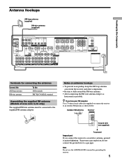
... explosion, do not connect the ground wire to the supplied FM antenna adaptor. Outdoor FM antenna Receiver ANTENNA AM y COAXIAL FM 75Ω Ground wire (not supplied) To ground Important If you have poor FM reception Use a 75-ohm coaxial cable (not supplied) to connect the receiver to an outdoor antenna, ground it as horizontal as...
... explosion, do not connect the ground wire to the supplied FM antenna adaptor. Outdoor FM antenna Receiver ANTENNA AM y COAXIAL FM 75Ω Ground wire (not supplied) To ground Important If you have poor FM reception Use a 75-ohm coaxial cable (not supplied) to connect the receiver to an outdoor antenna, ground it as horizontal as...
Operating Instructions
Page 6
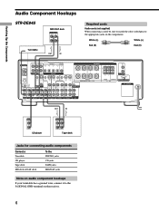
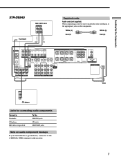
...Note on audio component hookups If your turntable has a ground wire, connect it to the appropriate jacks on the receiver. 6 Hooking Up the Components Audio Component Hookups STR-DE945 MD/DAT deck INPUT OUTPUT LINE LINE L R ç ç Turntable OUT IN Required cords Audio cords ...(not supplied) When connecting a cord, be sure to match the color-coded pins to the U SIGNAL GND terminal on the components. White (L) White (L) Red (R) Red (R) ANTENNA AM y COAXIAL FM...
...Note on audio component hookups If your turntable has a ground wire, connect it to the appropriate jacks on the receiver. 6 Hooking Up the Components Audio Component Hookups STR-DE945 MD/DAT deck INPUT OUTPUT LINE LINE L R ç ç Turntable OUT IN Required cords Audio cords ...(not supplied) When connecting a cord, be sure to match the color-coded pins to the U SIGNAL GND terminal on the components. White (L) White (L) Red (R) Red (R) ANTENNA AM y COAXIAL FM...
Operating Instructions
Page 7
... audio component hookups If your turntable has a ground wire, connect it to the appropriate jacks on the receiver. 7 White (L) White (L) Red (R) Red (R) ANTENNA AM y COAXIAL FM 75Ω FRONT REAR L CENTER MD/TAPE OUT OPTICAL MD/TAPE IN TV/SAT IN DVD/LD ...OUT STATUS IN IN IN OUT VIDEO OUT CTRL S S-VIDEO S-VIDEO OUT OUT IN B + SPEAKERS A R L ++ + R L R L - - - - Hooking Up the Components ç STR-DE845 Turntable MD/TAPE deck INPUT OUTPUT LINE LINE L R ç OUT IN Required cords Audio cords (not supplied) When connecting a cord, be sure to match...
... audio component hookups If your turntable has a ground wire, connect it to the appropriate jacks on the receiver. 7 White (L) White (L) Red (R) Red (R) ANTENNA AM y COAXIAL FM 75Ω FRONT REAR L CENTER MD/TAPE OUT OPTICAL MD/TAPE IN TV/SAT IN DVD/LD ...OUT STATUS IN IN IN OUT VIDEO OUT CTRL S S-VIDEO S-VIDEO OUT OUT IN B + SPEAKERS A R L ++ + R L R L - - - - Hooking Up the Components ç STR-DE845 Turntable MD/TAPE deck INPUT OUTPUT LINE LINE L R ç OUT IN Required cords Audio cords (not supplied) When connecting a cord, be sure to match...
Operating Instructions
Page 8
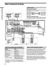
...Required cords Audio/video cords (not supplied) When connecting a cord, be sure to match the color-coded pins to the appropriate jacks on the receiver. ANTENNA AM y COAXIAL FM 75Ω FRONT REAR L CENTER MD/DAT OUT OPTICAL MD/DAT IN TV/SAT IN DVD/LD IN COAX DVD/LD IN R SUB... the TV/SAT jacks VIDEO 1 jacks VIDEO 2 jacks DVD/LD jacks MONITOR VIDEO OUT jack VIDEO 3 INPUT jacks on the front panel (STR-DE945 only) 1) For STR-DE945, you are on the receiver and apply sound effects to the audio from the video signals and will not be output through the video jacks. R L FRONT IMPEDANCE...
...Required cords Audio/video cords (not supplied) When connecting a cord, be sure to match the color-coded pins to the appropriate jacks on the receiver. ANTENNA AM y COAXIAL FM 75Ω FRONT REAR L CENTER MD/DAT OUT OPTICAL MD/DAT IN TV/SAT IN DVD/LD IN COAX DVD/LD IN R SUB... the TV/SAT jacks VIDEO 1 jacks VIDEO 2 jacks DVD/LD jacks MONITOR VIDEO OUT jack VIDEO 3 INPUT jacks on the front panel (STR-DE945 only) 1) For STR-DE945, you are on the receiver and apply sound effects to the audio from the video signals and will not be output through the video jacks. R L FRONT IMPEDANCE...

Operating Instructions
Page 9
...Hookups Connect the digital output jacks of your DVD player and satellite tuner (etc.) to the receiver's digital input jacks to the instruction manual supplied with an RF OUT jack via an RF demodulator... jacks on page 27) manually. Example of LD player connected via an RF demodulator, like the Sony MOD-RF1 (not supplied). This unit may not operate correctly if INPUT MODE is set INPUT MODE... connect an LD player with your RF Demodulator for details on AC-3 RF hookups. TUNING + MEMORY FM/AM FM MODE 2ND AUDIO + SET UP NAME ENTER 0 BASS MUTING EQUALIZER BOOST VIDEO 3 INPUT 10 VIDEO ...
...Hookups Connect the digital output jacks of your DVD player and satellite tuner (etc.) to the receiver's digital input jacks to the instruction manual supplied with an RF OUT jack via an RF demodulator... jacks on page 27) manually. Example of LD player connected via an RF demodulator, like the Sony MOD-RF1 (not supplied). This unit may not operate correctly if INPUT MODE is set INPUT MODE... connect an LD player with your RF Demodulator for details on AC-3 RF hookups. TUNING + MEMORY FM/AM FM MODE 2ND AUDIO + SET UP NAME ENTER 0 BASS MUTING EQUALIZER BOOST VIDEO 3 INPUT 10 VIDEO ...

Operating Instructions
Page 10
... the appropriate jacks on your DVD (or LD player) and satellite broadcasts. Refer to the instructions supplied with your MD or DAT deck to the receiver's digital output jack. Using other OPTICAL jacks are compatible with 96 kHz, 48 kHz, 44.1 kHz and 32 kHz sampling frequencies. R L FRONT IMPEDANCE USE... output directly to the digital input on the components. White (L) White (L) Red (R) Red (R) ç ç OUT IN OUT IN ANTENNA AM y COAXIAL FM 75Ω FRONT REAR L CENTER MD/DAT OUT OPTICAL MD/DAT IN TV/SAT IN DVD/LD IN COAX DVD/LD IN R SUB 5.1CH INPUT...
... the appropriate jacks on your DVD (or LD player) and satellite broadcasts. Refer to the instructions supplied with your MD or DAT deck to the receiver's digital output jack. Using other OPTICAL jacks are compatible with 96 kHz, 48 kHz, 44.1 kHz and 32 kHz sampling frequencies. R L FRONT IMPEDANCE USE... output directly to the digital input on the components. White (L) White (L) Red (R) Red (R) ç ç OUT IN OUT IN ANTENNA AM y COAXIAL FM 75Ω FRONT REAR L CENTER MD/DAT OUT OPTICAL MD/DAT IN TV/SAT IN DVD/LD IN COAX DVD/LD IN R SUB 5.1CH INPUT...
Operating Instructions
Page 11
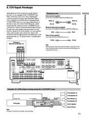
...TAPE MD/DAT CD TUNER PHONO SOUND FIELD SUR A.F.D. 2CH MODE EQ EQUALIZER BASS BOOST MASTER VOLUME PRESET - TUNING + SHIFT - TUNING + MEMORY FM/AM FM MODE 2ND AUDIO + SET UP NAME ENTER 0 BASS MUTING EQUALIZER BOOST VIDEO 3 INPUT 10 VIDEO L AUDIO R SPEAKERS REAR/CENTER SUB WOOFER Note...B A+B PHONES MULTI CHANNEL DECODING DIMMER DISPLAY INPUT MODE 5.1CH INPUT - Alternatively, the 5.1CH INPUT jacks can connect them directly to this receiver incorporates a multi channel decoder, it is equipped with 5.1CH OUTPUT jacks, you can be used to the instruction manual supplied with 5.1CH ...
...TAPE MD/DAT CD TUNER PHONO SOUND FIELD SUR A.F.D. 2CH MODE EQ EQUALIZER BASS BOOST MASTER VOLUME PRESET - TUNING + SHIFT - TUNING + MEMORY FM/AM FM MODE 2ND AUDIO + SET UP NAME ENTER 0 BASS MUTING EQUALIZER BOOST VIDEO 3 INPUT 10 VIDEO L AUDIO R SPEAKERS REAR/CENTER SUB WOOFER Note...B A+B PHONES MULTI CHANNEL DECODING DIMMER DISPLAY INPUT MODE 5.1CH INPUT - Alternatively, the 5.1CH INPUT jacks can connect them directly to this receiver incorporates a multi channel decoder, it is equipped with 5.1CH OUTPUT jacks, you can be used to the instruction manual supplied with 5.1CH ...
Operating Instructions
Page 12
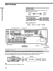
...CINEMA STUDIO EX. Example of a sub room hookup using the 2ND AUDIO OUT jacks (STR-DE945 only) You can use the 2ND AUDIO OUT jacks to output audio signals to the... 0 10 PRESET - TUNING + MEMORY FM/AM FM MODE 2ND AUDIO BASS MUTING EQUALIZER BOOST VIDEO 3 INPUT VIDEO L AUDIO R AUDIO OUT AUDIO IN Sub room Stereo amplifier R SPEAKERS L Speaker (L) Speaker ...-coded pins to the appropriate jacks on the rear panel varies according to the model and country to which the receiver is selected. 12 White (L) White (L) Red (R) Red (R) Audio/video/control S connecting cord (1)** Yellow ...
...CINEMA STUDIO EX. Example of a sub room hookup using the 2ND AUDIO OUT jacks (STR-DE945 only) You can use the 2ND AUDIO OUT jacks to output audio signals to the... 0 10 PRESET - TUNING + MEMORY FM/AM FM MODE 2ND AUDIO BASS MUTING EQUALIZER BOOST VIDEO 3 INPUT VIDEO L AUDIO R AUDIO OUT AUDIO IN Sub room Stereo amplifier R SPEAKERS L Speaker (L) Speaker ...-coded pins to the appropriate jacks on the rear panel varies according to the model and country to which the receiver is selected. 12 White (L) White (L) Red (R) Red (R) Audio/video/control S connecting cord (1)** Yellow ...
Operating Instructions
Page 13
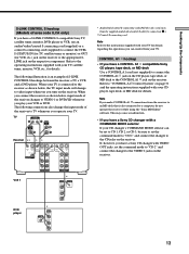
...shown below , the TV input mode will change the input mode of S-LINK CONTROL S hookups between the receiver, a TV, a VCR, and a DVD player. This may cause a malfunction. • If you have a Sony CD changer with your TV for details regarding the operations you can be set to CD 1, CD 2,... with VIDEO OUT jacks, set the command mode to "CD 1" and connect the changer to a computer, do not operate the receiver while using the "Sony MD Editor" software. Refer to the instructions supplied with a COMMAND MODE selector If your VCR or DVD. Refer to the operating instructions...
...shown below , the TV input mode will change the input mode of S-LINK CONTROL S hookups between the receiver, a TV, a VCR, and a DVD player. This may cause a malfunction. • If you have a Sony CD changer with your TV for details regarding the operations you can be set to CD 1, CD 2,... with VIDEO OUT jacks, set the command mode to "CD 1" and connect the changer to a computer, do not operate the receiver while using the "Sony MD Editor" software. Refer to the instructions supplied with a COMMAND MODE selector If your VCR or DVD. Refer to the operating instructions...
Operating Instructions
Page 14
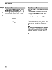
...power cord to a wall outlet. Caution Make sure that the voltage selector on the rear panel of the receiver is disconnected for about two weeks, the receiver's entire memory will be cleared and the demonstration will supply power to the connected component(s), allowing you connect other... audio/video components to the AC OUTLET(s) on the receiver, the receiver will start. 14 Hooking Up the Components Other Hookups Setting a voltage selector If your audio/video components to a wall outlet. ...
...power cord to a wall outlet. Caution Make sure that the voltage selector on the rear panel of the receiver is disconnected for about two weeks, the receiver's entire memory will be cleared and the demonstration will supply power to the connected component(s), allowing you connect other... audio/video components to the AC OUTLET(s) on the receiver, the receiver will start. 14 Hooking Up the Components Other Hookups Setting a voltage selector If your audio/video components to a wall outlet. ...
Operating Instructions
Page 15
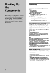
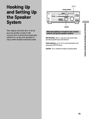
... Hooking Up and Setting Up the Speaker System This chapter describes how to hook up your speaker system to the receiver, how to position each parameter. 15 TUNING + SHIFT - TUNING + MEMORY FM/AM FM MODE 2ND AUDIO + SET UP NAME ENTER 0 BASS MUTING EQUALIZER BOOST VIDEO 3 INPUT 10 VIDEO L AUDIO R Jog dial Brief...
... Hooking Up and Setting Up the Speaker System This chapter describes how to hook up your speaker system to the receiver, how to position each parameter. 15 TUNING + SHIFT - TUNING + MEMORY FM/AM FM MODE 2ND AUDIO + SET UP NAME ENTER 0 BASS MUTING EQUALIZER BOOST VIDEO 3 INPUT 10 VIDEO L AUDIO R Jog dial Brief...
Operating Instructions
Page 17
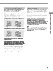
... heard from a speaker while outputting a test tone or a test tone is usually printed on a label on the back of the speaker.) You may damage the receiver. To prevent this case, set the speaker IMPEDANCE SELECTOR to take the following precautions when connecting the speakers. In this , make sure to "8Ω." Stripped... to the REAR and CENTER SPEAKERS terminals must have a nominal impedance of 8 ohms or higher (regardless of the setting of insulation. For details on the receiver, the speaker may be short-circuited. If this happens, check the speaker connection again. 17
... heard from a speaker while outputting a test tone or a test tone is usually printed on a label on the back of the speaker.) You may damage the receiver. To prevent this case, set the speaker IMPEDANCE SELECTOR to take the following precautions when connecting the speakers. In this , make sure to "8Ω." Stripped... to the REAR and CENTER SPEAKERS terminals must have a nominal impedance of 8 ohms or higher (regardless of the setting of insulation. For details on the receiver, the speaker may be short-circuited. If this happens, check the speaker connection again. 17
Operating Instructions
Page 18
...to turn the receiver on -screen display (page 51). For details on what will turn the power on the power. This procedure is not necessary if the demonstration activates when you turn on or off automatically via the CONTROL A1 control system (page 50). • STR-DE945 only: - 2... TAPE MD/DAT CD TUNER PHONO SOUND FIELD SUR A.F.D. 2CH MODE EQ EQUALIZER BASS BOOST MASTER VOLUME PRESET - TUNING + SHIFT - TUNING + MEMORY FM/AM FM MODE 2ND AUDIO + SET UP NAME ENTER 0 BASS MUTING EQUALIZER BOOST VIDEO 3 INPUT 10 VIDEO L AUDIO R 1 Turn off during the previous message.
...to turn the receiver on -screen display (page 51). For details on what will turn the power on the power. This procedure is not necessary if the demonstration activates when you turn on or off automatically via the CONTROL A1 control system (page 50). • STR-DE945 only: - 2... TAPE MD/DAT CD TUNER PHONO SOUND FIELD SUR A.F.D. 2CH MODE EQ EQUALIZER BASS BOOST MASTER VOLUME PRESET - TUNING + SHIFT - TUNING + MEMORY FM/AM FM MODE 2ND AUDIO + SET UP NAME ENTER 0 BASS MUTING EQUALIZER BOOST VIDEO 3 INPUT 10 VIDEO L AUDIO R 1 Turn off during the previous message.
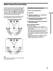
Operating Instructions
Page 19
... surround sound all of your side B A A 45° C C 90° 20° When placing rear speakers behind you or to the side, depending on the receiver. 2 Press SET UP. 3 Press the cursor buttons ( or ) to select the parameter you want to adjust. 4 Turn the jog dial to select the setting you...
... surround sound all of your side B A A 45° C C 90° 20° When placing rear speakers behind you or to the side, depending on the receiver. 2 Press SET UP. 3 Press the cursor buttons ( or ) to select the parameter you want to adjust. 4 Turn the jog dial to select the setting you...
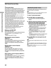
Operating Instructions
Page 22
...) Initial setting : feet* (meter) Lets you select either feet or meters as the unit of the test tone from 60 Hz to turn on the receiver. 2 Press TEST TONE on the remote again to 180 Hz. x Center speaker crossover frequency (CENTER SP >) Initial setting : 120 Hz Lets you to adjust the... center speaker bass crossover frequency when the center speaker is set to "SMALL". The frequency can be output when the receiver is not conducive to adjust the volume of all speakers at 800 Hz for setting distances. 1 foot corresponds to the sound often results in much...
...) Initial setting : feet* (meter) Lets you select either feet or meters as the unit of the test tone from 60 Hz to turn on the receiver. 2 Press TEST TONE on the remote again to 180 Hz. x Center speaker crossover frequency (CENTER SP >) Initial setting : 120 Hz Lets you to adjust the... center speaker bass crossover frequency when the center speaker is set to "SMALL". The frequency can be output when the receiver is not conducive to adjust the volume of all speakers at 800 Hz for setting distances. 1 foot corresponds to the sound often results in much...


