Dimensions Diagram
Page 1
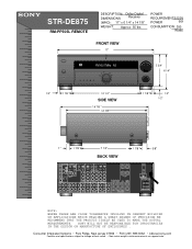
... subject to change without notice. • Non-metric weights and measurements are approximate. SONY WILL NOT BE RESPONSIBLE FOR INACCURACIES IN THE DESIGN OR MANUFACTURE OF ENCLOSURES . STR-DE875 RM-PP505L REMOTE DESCRIPTION: Dolby Digital DIMENSIONS Receiver (WHD): 17" x 6 1/4" x 14 7/8" WEIGHT: Approx 35 lbs POWER REQUIREMENTS...VIDEO S-VIDEO CTRL-S CTRL-S S-VIDEO S-VIDEO CTRL-S VIDEO OUT IN IN OUT OUT OUT IN IN OUT COAXIAL CONTROL A1 ll FM COAX FRONT REAR CNT FRONT REAR TV/SAT CNT DVD VIDEO 2 SUB WOOFER SUB WOOFER VIDEO 1 FRONT SURR SURROUND CNT BACK MULTI ...
... subject to change without notice. • Non-metric weights and measurements are approximate. SONY WILL NOT BE RESPONSIBLE FOR INACCURACIES IN THE DESIGN OR MANUFACTURE OF ENCLOSURES . STR-DE875 RM-PP505L REMOTE DESCRIPTION: Dolby Digital DIMENSIONS Receiver (WHD): 17" x 6 1/4" x 14 7/8" WEIGHT: Approx 35 lbs POWER REQUIREMENTS...VIDEO S-VIDEO CTRL-S CTRL-S S-VIDEO S-VIDEO CTRL-S VIDEO OUT IN IN OUT OUT OUT IN IN OUT COAXIAL CONTROL A1 ll FM COAX FRONT REAR CNT FRONT REAR TV/SAT CNT DVD VIDEO 2 SUB WOOFER SUB WOOFER VIDEO 1 FRONT SURR SURROUND CNT BACK MULTI ...
Operating Instructions
Page 1
4-234-334-12(2) FM Stereo FM-AM Receiver Operating Instructions STR-DE975 STR-DE875 © 2001 Sony Corporation
4-234-334-12(2) FM Stereo FM-AM Receiver Operating Instructions STR-DE975 STR-DE875 © 2001 Sony Corporation

Operating Instructions
Page 2
...'s attention to Article 82040 of the building, as close to persons. STR-DE975/DE875 Serial No. As an ENERGY STAR® partner, Sony Corporation has determined that any question or problem concerning your receiver, please consult your authority to radio communications. Consult the dealer or an... shock to the point of the following measures: - The operating voltage is indicated on the nameplate at the rear of the receiver with your Sony dealer regarding this product meets the ENERGY STAR® guidelines for a long time, be determined by one way. Refer to...
...'s attention to Article 82040 of the building, as close to persons. STR-DE975/DE875 Serial No. As an ENERGY STAR® partner, Sony Corporation has determined that any question or problem concerning your receiver, please consult your authority to radio communications. Consult the dealer or an... shock to the point of the following measures: - The operating voltage is indicated on the nameplate at the rear of the receiver with your Sony dealer regarding this product meets the ENERGY STAR® guidelines for a long time, be determined by one way. Refer to...
Operating Instructions
Page 3
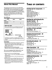
...this manual: z Indicates hints and tips for the STR-DE975, and STR-DE875. All rights reserved. **Manufactured under license from Digital Theater Systems, Inc. Conventions • The instructions in this manual describe the controls on the receiver. • The following icon is used for illustration...of differences Model Feature 5 audio inputs 4 audio inputs DE975 • DE875 • About area codes The area code of the receiver you purchased is clearly indicated in this manual, the STR-DE975 and the remote commander RM-PP505 are for making the task easier...
...this manual: z Indicates hints and tips for the STR-DE975, and STR-DE875. All rights reserved. **Manufactured under license from Digital Theater Systems, Inc. Conventions • The instructions in this manual describe the controls on the receiver. • The following icon is used for illustration...of differences Model Feature 5 audio inputs 4 audio inputs DE975 • DE875 • About area codes The area code of the receiver you purchased is clearly indicated in this manual, the STR-DE975 and the remote commander RM-PP505 are for making the task easier...
Operating Instructions
Page 4
... receiver. Before you received the following items with the receiver: • FM wire antenna (1) • AM loop antenna (1) • R6 (size-AA) batteries (2) • Audio/video/control S connecting cord (1) • Control S connecting cord (1) • STR-DE975 only • Remote commander RM-PP505L (remote) (1) • STR-DE875 ... Hooking Up the Components This chapter describes how to connect various audio and video components to the appropriate jacks on the receiver. Unpacking Check that you get started • Turn off the power to all components before you don't use a...
... receiver. Before you received the following items with the receiver: • FM wire antenna (1) • AM loop antenna (1) • R6 (size-AA) batteries (2) • Audio/video/control S connecting cord (1) • Control S connecting cord (1) • STR-DE975 only • Remote commander RM-PP505L (remote) (1) • STR-DE875 ... Hooking Up the Components This chapter describes how to connect various audio and video components to the appropriate jacks on the receiver. Unpacking Check that you get started • Turn off the power to all components before you don't use a...

Operating Instructions
Page 5
... a 75-ohm coaxial cable (not supplied) to connect the receiver to fully extend the FM wire antenna. • After connecting the FM wire antenna, keep the AM loop antenna away from the receiver and other components. • Be sure to an outdoor FM antenna as possible. FM COA7X5IΩAL Notes on antenna hookups • To...
... a 75-ohm coaxial cable (not supplied) to connect the receiver to fully extend the FM wire antenna. • After connecting the FM wire antenna, keep the AM loop antenna away from the receiver and other components. • Be sure to an outdoor FM antenna as possible. FM COA7X5IΩAL Notes on antenna hookups • To...
Operating Instructions
Page 6
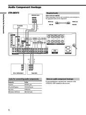
... SURROUND CENTER TV/SAT IN MD/DAT IN MD/DAT OUT COAXIAL DVD/LD IN L AM CONTROL A1 S-VIDEO OUT 2ND ROOM CTRL S IN COAXIAL FM 75Ω U L VIDEO OUT MONITOR R CTRL S S-VIDEO S-VIDEO CTRL S STATUS IN IN IN OUT CTRL S S-VIDEO S-VIDEO OUT OUT IN VIDEO IN .../DAT jacks Note on audio component hookups If your turntable has a ground wire, connect it to the appropriate jacks on the receiver. 6 ç Hooking Up the Components Audio Component Hookups STR-DE975 Turntable MD/DAT deck INPUT OUTPUT LINE LINE L R ç OUT IN Required cords Audio cords (not supplied) When ...
... SURROUND CENTER TV/SAT IN MD/DAT IN MD/DAT OUT COAXIAL DVD/LD IN L AM CONTROL A1 S-VIDEO OUT 2ND ROOM CTRL S IN COAXIAL FM 75Ω U L VIDEO OUT MONITOR R CTRL S S-VIDEO S-VIDEO CTRL S STATUS IN IN IN OUT CTRL S S-VIDEO S-VIDEO OUT OUT IN VIDEO IN .../DAT jacks Note on audio component hookups If your turntable has a ground wire, connect it to the appropriate jacks on the receiver. 6 ç Hooking Up the Components Audio Component Hookups STR-DE975 Turntable MD/DAT deck INPUT OUTPUT LINE LINE L R ç OUT IN Required cords Audio cords (not supplied) When ...
Operating Instructions
Page 7
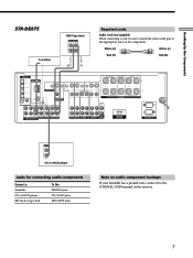
...AM CONTROL A1 S-VIDEO OUT CTRL S IN CTRL S S-VIDEO S-VIDEO CTRL S STATUS IN IN IN OUT CTRL S S-VIDEO S-VIDEO OUT OUT IN COAXIAL FM 75Ω U VIDEO OUT MONITOR VIDEO IN VIDEO IN VIDEO OUT VIDEO IN VIDEO OUT VIDEO IN IMPEDANCE USE 8 - 16Ω SPEAKERS SIGNAL GND L .../TAPE jacks Note on audio component hookups If your turntable has a ground wire, connect it to the appropriate jacks on the receiver. 7 Hooking Up the Components ç STR-DE875 Turntable MD/Tape deck INPUT OUTPUT LINE LINE L R ç OUT IN Required cords Audio cords (not supplied) When connecting...
...AM CONTROL A1 S-VIDEO OUT CTRL S IN CTRL S S-VIDEO S-VIDEO CTRL S STATUS IN IN IN OUT CTRL S S-VIDEO S-VIDEO OUT OUT IN COAXIAL FM 75Ω U VIDEO OUT MONITOR VIDEO IN VIDEO IN VIDEO OUT VIDEO IN VIDEO OUT VIDEO IN IMPEDANCE USE 8 - 16Ω SPEAKERS SIGNAL GND L .../TAPE jacks Note on audio component hookups If your turntable has a ground wire, connect it to the appropriate jacks on the receiver. 7 Hooking Up the Components ç STR-DE875 Turntable MD/Tape deck INPUT OUTPUT LINE LINE L R ç OUT IN Required cords Audio cords (not supplied) When connecting...

Operating Instructions
Page 8
...are connecting a separate TV tuner (or satellite tuner), connect both the audio and video output jacks to the receiver as shown above. Ç Ç Hooking Up the Components Video Component Hookups TV or satellite tuner OUTPUT...DAT IN MD/DAT OUT COAXIAL DVD/LD IN L AM CONTROL A1 S-VIDEO OUT 2ND ROOM CTRL S IN COAXIAL FM 75Ω U L VIDEO OUT MONITOR R CTRL S S-VIDEO S-VIDEO CTRL S STATUS IN IN IN OUT CTRL... jacks VIDEO 2 jacks DVD/LD jacks MONITOR VIDEO OUT jack 1) For STR-DE975, you are on the receiver and apply sound effects to the TV/ SAT AUDIO IN jacks on a separate bus from...
...are connecting a separate TV tuner (or satellite tuner), connect both the audio and video output jacks to the receiver as shown above. Ç Ç Hooking Up the Components Video Component Hookups TV or satellite tuner OUTPUT...DAT IN MD/DAT OUT COAXIAL DVD/LD IN L AM CONTROL A1 S-VIDEO OUT 2ND ROOM CTRL S IN COAXIAL FM 75Ω U L VIDEO OUT MONITOR R CTRL S S-VIDEO S-VIDEO CTRL S STATUS IN IN IN OUT CTRL... jacks VIDEO 2 jacks DVD/LD jacks MONITOR VIDEO OUT jack 1) For STR-DE975, you are on the receiver and apply sound effects to the TV/ SAT AUDIO IN jacks on a separate bus from...
Operating Instructions
Page 9
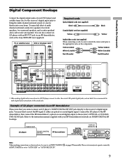
... cannot connect an LD player's DOLBY DIGITAL RF OUT jack directly to either an optical or coaxial digital signal. TUNING + LEVEL SURR EQ MEMORY SHIFT FM MODE FM AM VIDEO L AUDIO R - Yellow (video) Yellow (video) White (L/audio) White (L/audio) Red (R/audio) Red (R/audio) DIGITAL OPTICAL DVD/LD ...120W/1A MAX AC 120V 60Hz AC OUTLET * When making connections as the Sony MOD-RF1 (not supplied). The receiver may not operate correctly if INPUT MODE is recommended to make digital audio connections to the receiver's OPTICAL or COAXIAL DVD/LD IN jack. To enjoy full effect of multi...
... cannot connect an LD player's DOLBY DIGITAL RF OUT jack directly to either an optical or coaxial digital signal. TUNING + LEVEL SURR EQ MEMORY SHIFT FM MODE FM AM VIDEO L AUDIO R - Yellow (video) Yellow (video) White (L/audio) White (L/audio) Red (R/audio) Red (R/audio) DIGITAL OPTICAL DVD/LD ...120W/1A MAX AC 120V 60Hz AC OUTLET * When making connections as the Sony MOD-RF1 (not supplied). The receiver may not operate correctly if INPUT MODE is recommended to make digital audio connections to the receiver's OPTICAL or COAXIAL DVD/LD IN jack. To enjoy full effect of multi...
Operating Instructions
Page 10
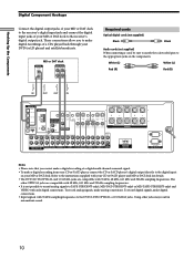
... SURROUND CENTER TV/SAT IN MD/DAT IN MD/DAT OUT COAXIAL DVD/LD IN L AM CONTROL A1 S-VIDEO OUT 2ND ROOM CTRL S IN COAXIAL FM 75Ω U L VIDEO OUT MONITOR R CTRL S S-VIDEO S-VIDEO CTRL S STATUS IN IN IN OUT CTRL S S-VIDEO S-VIDEO OUT OUT IN VIDEO IN VIDEO IN VIDEO... to TAPE (STR-DE975 only), MD/DAT (STR-DE975 only) or MD/TAPE (STR-DE875 only) and VIDEO with 96 kHz, 48 kHz, 44.1 kHz and 32 kHz sampling frequencies. ç ç Hooking Up the Components Digital Component Hookups Connect the digital output jacks of your MD or DAT deck to the receiver's digital input...
... SURROUND CENTER TV/SAT IN MD/DAT IN MD/DAT OUT COAXIAL DVD/LD IN L AM CONTROL A1 S-VIDEO OUT 2ND ROOM CTRL S IN COAXIAL FM 75Ω U L VIDEO OUT MONITOR R CTRL S S-VIDEO S-VIDEO CTRL S STATUS IN IN IN OUT CTRL S S-VIDEO S-VIDEO OUT OUT IN VIDEO IN VIDEO IN VIDEO... to TAPE (STR-DE975 only), MD/DAT (STR-DE975 only) or MD/TAPE (STR-DE875 only) and VIDEO with 96 kHz, 48 kHz, 44.1 kHz and 32 kHz sampling frequencies. ç ç Hooking Up the Components Digital Component Hookups Connect the digital output jacks of your MD or DAT deck to the receiver's digital input...
Operating Instructions
Page 11
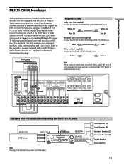
... C DIGITAL CONCERT HALL 6.1 CH DECODING A B SOUND FIELD A.F.D. Alternatively, the MULTI CH IN jacks can connect them directly to the receiver to enjoy multichannel software encoded in formats other than Dolby Digital and DTS. These connections allow you to enjoy the sound of your surround ... FM AM - DIRECT EQUALIZER MUTING INPUT MODE MODE FUNCTION 2ND ROOM SPEAKERS SURROUND/CENTER SUB WOOFER Note See page 16 for details on speaker system hookup. Hooking Up the Components MULTI CH IN Hookups Although this receiver incorporates a multi channel decoder, it is equipped...
... C DIGITAL CONCERT HALL 6.1 CH DECODING A B SOUND FIELD A.F.D. Alternatively, the MULTI CH IN jacks can connect them directly to the receiver to enjoy multichannel software encoded in formats other than Dolby Digital and DTS. These connections allow you to enjoy the sound of your surround ... FM AM - DIRECT EQUALIZER MUTING INPUT MODE MODE FUNCTION 2ND ROOM SPEAKERS SURROUND/CENTER SUB WOOFER Note See page 16 for details on speaker system hookup. Hooking Up the Components MULTI CH IN Hookups Although this receiver incorporates a multi channel decoder, it is equipped...

Operating Instructions
Page 13
... TV. The following illustration is an example of the receiver to TV whenever you operate your VCR or DVD. If, however, you have a Sony CD changer with your TV is also connected to a computer, do not operate the receiver while using the "Sony MD Editor" software. DVD player S-LINK IN * ... COMMAND MODE selector If your TV, satellite tuner, monitor, VCR, etc., for details. Refer to the CD jacks on the receiver. This may cause a malfunction. • If you have a Sony CD changer with your CD changer's COMMAND MODE selector can be set to CD 1, CD 2, or CD 3, be sure to...
... TV. The following illustration is an example of the receiver to TV whenever you operate your VCR or DVD. If, however, you have a Sony CD changer with your TV is also connected to a computer, do not operate the receiver while using the "Sony MD Editor" software. DVD player S-LINK IN * ... COMMAND MODE selector If your TV, satellite tuner, monitor, VCR, etc., for details. Refer to the CD jacks on the receiver. This may cause a malfunction. • If you have a Sony CD changer with your CD changer's COMMAND MODE selector can be set to CD 1, CD 2, or CD 3, be sure to...

Operating Instructions
Page 14
... you connect other audio/video components to the AC OUTLET(s) on the receiver, the receiver will supply power to the connected component(s), allowing you to this receiver to a wall outlet: • Connect the speaker system to the receiver's AC OUTLET(s) does not exceed the wattage stated on the rear panel.... Caution Make sure that the total power consumption of the component(s) connected to the receiver (see page 16). Hooking Up the Components Digital Component Hookups Connecting the AC power cord Before connecting the AC power cord of this ...
... you connect other audio/video components to the AC OUTLET(s) on the receiver, the receiver will supply power to the connected component(s), allowing you to this receiver to a wall outlet: • Connect the speaker system to the receiver's AC OUTLET(s) does not exceed the wattage stated on the rear panel.... Caution Make sure that the total power consumption of the component(s) connected to the receiver (see page 16). Hooking Up the Components Digital Component Hookups Connecting the AC power cord Before connecting the AC power cord of this ...
Operating Instructions
Page 15
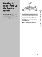
...B C DIGITAL CONCERT HALL 6.1 CH DECODING A B SOUND FIELD A.F.D. MODE 2CH ENTER MULTI /2CH A. TUNING + - TUNING + LEVEL SURR EQ MEMORY SHIFT FM MODE FM AM VIDEO L AUDIO R - Jog dial: Use to adjust the setting of buttons and control used to set up the speaker system SET UP button: Press...Setting Up the Speaker System Hooking Up and Setting Up the Speaker System This chapter describes how to hook up your speaker system to the receiver, how to position each parameter. 15 SET UP Jog dial ? / 1 MULTI CHANNEL DECODING MASTER VOLUME + SPEAKERS DISPLAY PHONES VIDEO 3...
...B C DIGITAL CONCERT HALL 6.1 CH DECODING A B SOUND FIELD A.F.D. MODE 2CH ENTER MULTI /2CH A. TUNING + - TUNING + LEVEL SURR EQ MEMORY SHIFT FM MODE FM AM VIDEO L AUDIO R - Jog dial: Use to adjust the setting of buttons and control used to set up the speaker system SET UP button: Press...Setting Up the Speaker System Hooking Up and Setting Up the Speaker System This chapter describes how to hook up your speaker system to the receiver, how to position each parameter. 15 SET UP Jog dial ? / 1 MULTI CHANNEL DECODING MASTER VOLUME + SPEAKERS DISPLAY PHONES VIDEO 3...

Operating Instructions
Page 17
... as indicated in the table below. Check the instruction manual supplied with your speakers if you turn off the receiver. When you turn the power off the receiver. 17 After connecting all the speakers are touching each speaker cord does not touch another speaker terminal or the ... ohms or higher (regardless of the setting of insulation. To avoid damaging your speaker is usually printed on a label on the receiver, the speaker may damage the receiver. Note Be sure to excessive removal of the IMPEDANCE SELECTOR). If no sound is heard from a speaker while outputting a test ...
... as indicated in the table below. Check the instruction manual supplied with your speakers if you turn off the receiver. When you turn the power off the receiver. 17 After connecting all the speakers are touching each speaker cord does not touch another speaker terminal or the ... ohms or higher (regardless of the setting of insulation. To avoid damaging your speaker is usually printed on a label on the receiver, the speaker may damage the receiver. Note Be sure to excessive removal of the IMPEDANCE SELECTOR). If no sound is heard from a speaker while outputting a test ...
Operating Instructions
Page 18
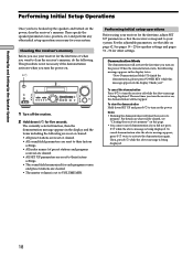
... view the demonstration Hold down SET UP and press ?/1 to VOLUME MIN. To cancel demonstration after the above message is set to turn the receiver off the receiver. 2 Hold down ?/1 for your system. This procedure is not necessary if the demonstration activates when you turn on the power. For the adjustable ... speakers and turned on . 1/u ? / 1 MULTI CHANNEL DECODING MASTER VOLUME + SPEAKERS DISPLAY PHONES VIDEO 3 INPUT DIMMER ON SCREEN PRESET - For details on what will clear the receiver's memory. TUNING + LEVEL SURR EQ MEMORY SHIFT FM MODE FM AM VIDEO L AUDIO R -
... view the demonstration Hold down SET UP and press ?/1 to VOLUME MIN. To cancel demonstration after the above message is set to turn the receiver off the receiver. 2 Hold down ?/1 for your system. This procedure is not necessary if the demonstration activates when you turn on the power. For the adjustable ... speakers and turned on . 1/u ? / 1 MULTI CHANNEL DECODING MASTER VOLUME + SPEAKERS DISPLAY PHONES VIDEO 3 INPUT DIMMER ON SCREEN PRESET - For details on what will clear the receiver's memory. TUNING + LEVEL SURR EQ MEMORY SHIFT FM MODE FM AM VIDEO L AUDIO R -

Operating Instructions
Page 19
... speaker farther away from the listening position than the front speakers. Specifying the speaker parameters 1 Press ?/1 to turn on a stand or hanging it on the receiver. 2 Press SET UP. 3 Press the cursor buttons ( or ) to select the parameter you want . D 20° When placing the surround speakers behind the listening position...
... speaker farther away from the listening position than the front speakers. Specifying the speaker parameters 1 Press ?/1 to turn on a stand or hanging it on the receiver. 2 Press SET UP. 3 Press the cursor buttons ( or ) to select the parameter you want . D 20° When placing the surround speakers behind the listening position...
Operating Instructions
Page 21
... front speakers, the position of the sub woofer, and the cut-off frequency of the overall sound may produce better bass. z About speaker distances This receiver allows you cannot obtain a satisfactory surround effect because the surround speakers are too close, setting the surround speaker distance closer (shorter) than the front speakers...
... front speakers, the position of the sub woofer, and the cut-off frequency of the overall sound may produce better bass. z About speaker distances This receiver allows you cannot obtain a satisfactory surround effect because the surround speakers are too close, setting the surround speaker distance closer (shorter) than the front speakers...
Operating Instructions
Page 23
... 37. When using a passive subwoofer powered by a separate power amplifier, it may be made via the front panel using the remote. 23 Note This receiver incorporates a new test tone with a frequency centered at 800 Hz for the front L/R speakers is selected (qh on page 28). 4 Adjust the LEVEL...turn FUNCTION to select the component (except connected to select the mode you want. Turn on the connected component, start playing, then turn on the receiver. 2 Press TEST TONE on the remote. For details on the main unit or press MASTER VOL +/- on the remote. "TEST TONE" appears in...
... 37. When using a passive subwoofer powered by a separate power amplifier, it may be made via the front panel using the remote. 23 Note This receiver incorporates a new test tone with a frequency centered at 800 Hz for the front L/R speakers is selected (qh on page 28). 4 Adjust the LEVEL...turn FUNCTION to select the component (except connected to select the mode you want. Turn on the connected component, start playing, then turn on the receiver. 2 Press TEST TONE on the remote. For details on the main unit or press MASTER VOL +/- on the remote. "TEST TONE" appears in...


