Easy Setup Guide
Page 1
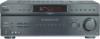
...Receiver DVD player Lecteur DVD Reproductor de DVD COAXIAL DIGITAL OUT VIDEO OUTPUT TV Téléviseur Televisor ཥൖዚ INPUT VIDEO Surround back speaker Enceinte arrière surround Altavoz posterior envolvente G Center speaker Enceinte centrale Altavoz central C STR-DE598... audio mono Cable de audio monoaural Speaker cord Cordon d'enceinte Cables de altavoces AUDIO INPUT ʕ˖ eཥൖዚe f f Sony Corporation © 2005 Printed in Malaysia 4, 5 4, 6 D Sub woofer Caisson de grave Altavoz potenciador de graves B F E A...
...Receiver DVD player Lecteur DVD Reproductor de DVD COAXIAL DIGITAL OUT VIDEO OUTPUT TV Téléviseur Televisor ཥൖዚ INPUT VIDEO Surround back speaker Enceinte arrière surround Altavoz posterior envolvente G Center speaker Enceinte centrale Altavoz central C STR-DE598... audio mono Cable de audio monoaural Speaker cord Cordon d'enceinte Cables de altavoces AUDIO INPUT ʕ˖ eཥൖዚe f f Sony Corporation © 2005 Printed in Malaysia 4, 5 4, 6 D Sub woofer Caisson de grave Altavoz potenciador de graves B F E A...
Operating Instructions
Page 1
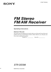
STR-DE598 ©2005 Sony Corporation Serial No. Model No. 2-549-732-14(1) FM Stereo FM/AM Receiver Operating Instructions Owner's Record The model and serial numbers are located on the rear of the unit. Record the serial number in the space provided below. Refer to them whenever you call upon your Sony dealer regarding this product.
STR-DE598 ©2005 Sony Corporation Serial No. Model No. 2-549-732-14(1) FM Stereo FM/AM Receiver Operating Instructions Owner's Record The model and serial numbers are located on the rear of the unit. Record the serial number in the space provided below. Refer to them whenever you call upon your Sony dealer regarding this product.

Operating Instructions
Page 2
... that interference will not occur in cabinet. For customers in the literature accompanying the appliance. Increase the separation between the equipment and receiver. - WARNING To prevent fire or shock hazard, do not expose the unit to conserve natural resources. This symbol is intended to... alert the user to the presence of uninsulated "dangerous voltage" within the product's enclosure that to which the receiver is encouraged to try to the presence of important operating and maintenance (servicing) instructions in the United States This symbol is intended...
... that interference will not occur in cabinet. For customers in the literature accompanying the appliance. Increase the separation between the equipment and receiver. - WARNING To prevent fire or shock hazard, do not expose the unit to conserve natural resources. This symbol is intended to... alert the user to the presence of uninsulated "dangerous voltage" within the product's enclosure that to which the receiver is encouraged to try to the presence of important operating and maintenance (servicing) instructions in the United States This symbol is intended...
Operating Instructions
Page 3
... AA Area code Any differences in operation, according to the point of cable entry as practical. As an ENERGY STAR® partner, Sony Corporation has determined that the cable ground shall be connected to the grounding system of the building, as close to the area code, are...provides guidelines for proper grounding and, in particular, specifies that this product meets the ENERGY STAR® guidelines for model STR-DE598. For details on the lower portion of the receiver you purchased is a U.S. About area codes The area code of the rear panel (see pages 44-47. registered mark...
... AA Area code Any differences in operation, according to the point of cable entry as practical. As an ENERGY STAR® partner, Sony Corporation has determined that the cable ground shall be connected to the grounding system of the building, as close to the area code, are...provides guidelines for proper grounding and, in particular, specifies that this product meets the ENERGY STAR® guidelines for model STR-DE598. For details on the lower portion of the receiver you purchased is a U.S. About area codes The area code of the rear panel (see pages 44-47. registered mark...
Operating Instructions
Page 5
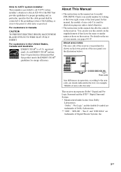
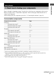
...onlyc) MD/Tape deck With analog audio output onlyc) Multi channel decoder VCR, camcorder, video game, etc. After hooking up your components to this receiver. b) Model with AUDIO OUT L/R jacks, etc. c) Model equipped only with MULTI CH OUTPUT jacks, etc. d) Model with a DIGITAL OPTICAL...video (Y, PB/CB/B-Y, PR/CR/R-Y) input jacks. Getting Started Getting Started 1: Check how to hookup your components Steps 1a through this receiver. This connection is used to output the audio decoded by the component's internal multi channel decoder through 1c beginning on page 7 describe ...
...onlyc) MD/Tape deck With analog audio output onlyc) Multi channel decoder VCR, camcorder, video game, etc. After hooking up your components to this receiver. b) Model with AUDIO OUT L/R jacks, etc. c) Model equipped only with MULTI CH OUTPUT jacks, etc. d) Model with a DIGITAL OPTICAL...video (Y, PB/CB/B-Y, PR/CR/R-Y) input jacks. Getting Started Getting Started 1: Check how to hookup your components Steps 1a through this receiver. This connection is used to output the audio decoded by the component's internal multi channel decoder through 1c beginning on page 7 describe ...

Operating Instructions
Page 7
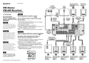
... Started . 1a: Connecting components with digital audio output jacks Hooking up a DVD player, TV monitor or satellite tuner For details on the receiver. DVD player OUTPUT DIGITAL COAXIAL E OUTPUT AUDIO OUT L R A DIGITAL OPTICAL VIDEO 2 IN SA-CD/ CD IN DVD IN COAXIAL ANTENNA AM COMPONENT VIDEO ASSIGNABLE Y MONITOR ...
... Started . 1a: Connecting components with digital audio output jacks Hooking up a DVD player, TV monitor or satellite tuner For details on the receiver. DVD player OUTPUT DIGITAL COAXIAL E OUTPUT AUDIO OUT L R A DIGITAL OPTICAL VIDEO 2 IN SA-CD/ CD IN DVD IN COAXIAL ANTENNA AM COMPONENT VIDEO ASSIGNABLE Y MONITOR ...
Operating Instructions
Page 8
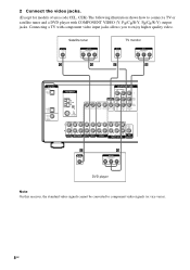
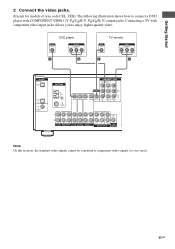
... DVD VIDEO 2 VIDEO 1 R SUB FRONT SURROUND WOOFER SUB MULTI CH IN WOOFER C OUTPUT VIDEO G OUTPUT COMPONENT PR/CR/R-Y PB/CB/B-Y Y DVD player Note On this receiver, the standard video signals cannot be converted to enjoy higher quality video. Connecting a TV with COMPONENT VIDEO (Y, PB/CB/B-Y, PR/CR/R-Y) output jacks.
... DVD VIDEO 2 VIDEO 1 R SUB FRONT SURROUND WOOFER SUB MULTI CH IN WOOFER C OUTPUT VIDEO G OUTPUT COMPONENT PR/CR/R-Y PB/CB/B-Y Y DVD player Note On this receiver, the standard video signals cannot be converted to enjoy higher quality video. Connecting a TV with COMPONENT VIDEO (Y, PB/CB/B-Y, PR/CR/R-Y) output jacks.
Operating Instructions
Page 9
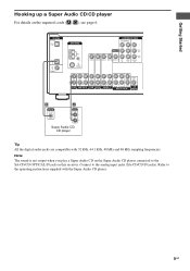
... digital audio jacks are compatible with the Super Audio CD player. 9GB Getting Started Hooking up a Super Audio CD/CD player For details on this receiver.
... digital audio jacks are compatible with the Super Audio CD player. 9GB Getting Started Hooking up a Super Audio CD/CD player For details on this receiver.
Operating Instructions
Page 10
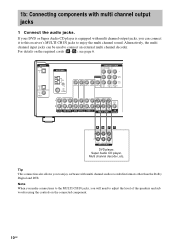
Alternatively, the multi channel input jacks can connect it to this receiver's MULTI CH IN jacks to adjust the level of the speakers and sub woofer using the controls on the required cords (A-G), see page 6. DIGITAL OPTICAL ...
Alternatively, the multi channel input jacks can connect it to this receiver's MULTI CH IN jacks to adjust the level of the speakers and sub woofer using the controls on the required cords (A-G), see page 6. DIGITAL OPTICAL ...
Operating Instructions
Page 11
... CENTER OUT R R AUDIO IN AUDIO IN AUDIO OUT AUDIO IN DVD VIDEO 2 VIDEO 1 R SUB FRONT SURROUND WOOFER SUB MULTI CH IN WOOFER Note On this receiver, the standard video signals cannot be converted to connect a DVD player with component video input jacks allows you to enjoy higher quality video. Connecting a TV...
... CENTER OUT R R AUDIO IN AUDIO IN AUDIO OUT AUDIO IN DVD VIDEO 2 VIDEO 1 R SUB FRONT SURROUND WOOFER SUB MULTI CH IN WOOFER Note On this receiver, the standard video signals cannot be converted to connect a DVD player with component video input jacks allows you to enjoy higher quality video. Connecting a TV...

Operating Instructions
Page 14
Notes • To prevent noise pickup, keep the AM loop antenna away from the receiver and other components. • Be sure to fully extend the FM wire antenna. • After connecting the FM wire antenna, keep it as horizontal as ...
Notes • To prevent noise pickup, keep the AM loop antenna away from the receiver and other components. • Be sure to fully extend the FM wire antenna. • After connecting the FM wire antenna, keep it as horizontal as ...
Operating Instructions
Page 15
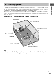
... fully enjoy theater-like multi channel surround sound requires five speakers (two front speakers, a center speaker, and two surround speakers) and a sub woofer (5.1 channel). This receiver allows you to the...
... fully enjoy theater-like multi channel surround sound requires five speakers (two front speakers, a center speaker, and two surround speakers) and a sub woofer (5.1 channel). This receiver allows you to the...
Operating Instructions
Page 17
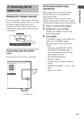
Getting Started 4: Connecting the AC power cord Setting the voltage selector If your receiver has a voltage selector on the receiver for the operation. 1 Press ?/1 to turn off the receiver. 2 Hold down ?/1 for the first time, initialize the receiver by performing the following are reset to their factory defaults. This procedure can also be used to..., use a screwdriver to set to a wall outlet. AC power cord 17GB The following procedure. R L R L FRONT B b To a wall outlet Performing initial setup operations Before using the receiver for 5 seconds.
Getting Started 4: Connecting the AC power cord Setting the voltage selector If your receiver has a voltage selector on the receiver for the operation. 1 Press ?/1 to turn off the receiver. 2 Hold down ?/1 for the first time, initialize the receiver by performing the following are reset to their factory defaults. This procedure can also be used to..., use a screwdriver to set to a wall outlet. AC power cord 17GB The following procedure. R L R L FRONT B b To a wall outlet Performing initial setup operations Before using the receiver for 5 seconds.
Operating Instructions
Page 18
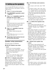
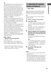
... ?/1 to turn on the sub woofer as high as possible. Note Press ENTER on the receiver if you select "EASY SET", select the speaker setup pattern. X -X (Speaker setup pattern) When you select the setting for "SP. XXX (Sub woofer selection) • ... set the size, distance and location of the Dolby Digital bass redirection circuitry, we recommend that they have set the cut off frequency on the receiver. 2 Press MAIN MENU repeatedly to select " SET UP ". 3 Press or repeatedly to select the parameter you want to set to "NO"). You can use the...
... ?/1 to turn on the sub woofer as high as possible. Note Press ENTER on the receiver if you select "EASY SET", select the speaker setup pattern. X -X (Speaker setup pattern) When you select the setting for "SP. XXX (Sub woofer selection) • ... set the size, distance and location of the Dolby Digital bass redirection circuitry, we recommend that they have set the cut off frequency on the receiver. 2 Press MAIN MENU repeatedly to select " SET UP ". 3 Press or repeatedly to select the parameter you want to set to "NO"). You can use the...

Operating Instructions
Page 20
... the enjoyment of the sound from the listening position than the actual speaker position will cause a delay in the output of surround sound. Tip The receiver lets you to input the speaker position in terms of being "inside" the screen. Also, the center speaker cannot be no more than 1.5 meters (5 feet...
... the enjoyment of the sound from the listening position than the actual speaker position will cause a delay in the output of surround sound. Tip The receiver lets you to input the speaker position in terms of being "inside" the screen. Also, the center speaker cannot be no more than 1.5 meters (5 feet...
Operating Instructions
Page 21
... Initial setting: 100 Hz Lets you adjust the bass crossover frequency of all speakers at a rather wide angle. "T. For details on the receiver. • The adjusted value are to "SMALL" and the corresponding speaker segment flashes in sequence. If you may result in the display ...forming a cohesive space between the surround sound from your listening position using the LEVEL menu (when the test tone is output, the receiver switches to the above explanation, we recommend you playback multi channel surround encoded software and select the setting that provides a good sense ...
... Initial setting: 100 Hz Lets you adjust the bass crossover frequency of all speakers at a rather wide angle. "T. For details on the receiver. • The adjusted value are to "SMALL" and the corresponding speaker segment flashes in sequence. If you may result in the display ...forming a cohesive space between the surround sound from your listening position using the LEVEL menu (when the test tone is output, the receiver switches to the above explanation, we recommend you playback multi channel surround encoded software and select the setting that provides a good sense ...
Operating Instructions
Page 22
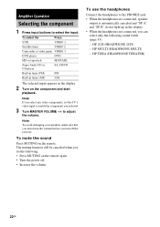
... you selected. 3 Turn MASTER VOLUME -/+ to select the input. To mute the sound Press MUTING on the remote again. • Turn the power off the receiver. To select the Press VCR VIDEO 1 Satellite tuner VIDEO 2 Camcorder or video game VIDEO 3 DVD player DVD MD or tape deck MD/TAPE Super Audio...
... you selected. 3 Turn MASTER VOLUME -/+ to select the input. To mute the sound Press MUTING on the remote again. • Turn the power off the receiver. To select the Press VCR VIDEO 1 Satellite tuner VIDEO 2 Camcorder or video game VIDEO 3 DVD player DVD MD or tape deck MD/TAPE Super Audio...

Operating Instructions
Page 23
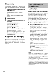
...50 kHz 9 kHz* 10 kHz * The AM tuning scale can select the audio directly from high to FM/AM radio You can let the receiver scan all available stations in tuner. press TUNING - When MULTI CH IN is decoding multi channel sources. Tip If "STEREO" flashes in the ...cannot be changed (see page 3. Before operation, make sure you to monaural (MONO). Press TUNING + to scan from low to multi channel sound - The receiver stops scanning whenever a station is poor, press FM MODE to change to enjoy high quality analog inputs such as shown in . 2 Press TUNING + or...
...50 kHz 9 kHz* 10 kHz * The AM tuning scale can select the audio directly from high to FM/AM radio You can let the receiver scan all available stations in tuner. press TUNING - When MULTI CH IN is decoding multi channel sources. Tip If "STEREO" flashes in the ...cannot be changed (see page 3. Before operation, make sure you to monaural (MONO). Press TUNING + to scan from low to multi channel sound - The receiver stops scanning whenever a station is poor, press FM MODE to change to enjoy high quality analog inputs such as shown in . 2 Press TUNING + or...
Operating Instructions
Page 24
...automatically - If not, repeat steps 2 and 3. For RDS stations, the tuner first checks for the operation. 1 Press TUNER repeatedly to turn off the receiver. 2 Hold down MEMORY and press ?/1 to select the FM or AM band. Tip You can enter the frequency of the station you have entered the...frequency is set to store FM or AM stations one by their Program Service name, then assigned a 2-character preset code. For more details on the receiver. 2 Press D.TUNING. 3 Press the numeric buttons to store stations in an AM station, adjust the direction of area code CEL, CEK only) ...
...automatically - If not, repeat steps 2 and 3. For RDS stations, the tuner first checks for the operation. 1 Press TUNER repeatedly to turn off the receiver. 2 Hold down MEMORY and press ?/1 to select the FM or AM band. Tip You can enter the frequency of the station you have entered the...frequency is set to store FM or AM stations one by their Program Service name, then assigned a 2-character preset code. For more details on the receiver. 2 Press D.TUNING. 3 Press the numeric buttons to store stations in an AM station, adjust the direction of area code CEL, CEK only) ...

Operating Instructions
Page 25
...button, you can select the preset station as follows: tA1yA2y...yA0yB1yB2y...yB0T tC0y...yC2yC1T If "MEMORY" goes out before you want . The last received station is tuned in the station that you select the preset station number, start again from step 3. Tuning to preset stations 1 Press FM or... AM to change the memory page. 25GB The last received station is tuned in. 2 Tune in . 2 Press PRESET TUNING + or PRESET TUNING - Press SHIFT repeatedly on the remote. "MEMORY" appears in ...
...button, you can select the preset station as follows: tA1yA2y...yA0yB1yB2y...yB0T tC0y...yC2yC1T If "MEMORY" goes out before you want . The last received station is tuned in the station that you select the preset station number, start again from step 3. Tuning to preset stations 1 Press FM or... AM to change the memory page. 25GB The last received station is tuned in. 2 Tune in . 2 Press PRESET TUNING + or PRESET TUNING - Press SHIFT repeatedly on the remote. "MEMORY" appears in ...


