
Dimensions Diagram
Page 1
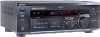
... • b2b.sel.sony.com Features and specifications subject to change without notice. • Non-metric weights and measurements are approximate. STR-DE445 RM-U304 REMOTE CONTROL DESCRIPTION: Dolby Digital DIMENSIONS Receiver (WHD): 17" x... 6 1/4" x 12" WEIGHT: Approx 17 lbs FRONT VIEW 17" POWER REQUIREMENTS:120V POWER 60H CONSUMPTION: 250 Watts R FM102.7MHz A3 5 3/4" 6 1/4" 5/8" 1 3/4 " 12 1/4 " SIDE VIEW 12 " 10 1/2" 1 3/4 " 5/8" 1/2" 1 1/8" 1 3/4 " 5" 2 " BACK VIEW FM...
... • b2b.sel.sony.com Features and specifications subject to change without notice. • Non-metric weights and measurements are approximate. STR-DE445 RM-U304 REMOTE CONTROL DESCRIPTION: Dolby Digital DIMENSIONS Receiver (WHD): 17" x... 6 1/4" x 12" WEIGHT: Approx 17 lbs FRONT VIEW 17" POWER REQUIREMENTS:120V POWER 60H CONSUMPTION: 250 Watts R FM102.7MHz A3 5 3/4" 6 1/4" 5/8" 1 3/4 " 12 1/4 " SIDE VIEW 12 " 10 1/2" 1 3/4 " 5/8" 1/2" 1 1/8" 1 3/4 " 5" 2 " BACK VIEW FM...
Operating Instructions (Receiver)
Page 3
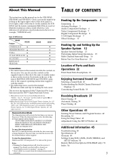
...Up the Speaker System 12 Speaker System Hookup 13 Performing Initial Setup Operations 15 Multi Channel Surround Setup 16 Before You Use Your Receiver 20 Location of the remote. In this manual, the STRDE545 and the remote commander RM-U304 are for the STR-DE545, STR-DE445 and STR-SE501. ...SUR, LEVEL, BASS/TREBLE, and SET UP buttons 50 Remote Button Descriptions (STR-DE445 only) 51 Index 54 3 "Dolby", "AC-3", "Pro Logic" and the double-D symbol a are trademarks of differences Model Feature DE545 CONTROL A1-II • SPEAKERS FRONT B • S-Video • TV/SAT OPTICAL IN •...
...Up the Speaker System 12 Speaker System Hookup 13 Performing Initial Setup Operations 15 Multi Channel Surround Setup 16 Before You Use Your Receiver 20 Location of the remote. In this manual, the STRDE545 and the remote commander RM-U304 are for the STR-DE545, STR-DE445 and STR-SE501. ...SUR, LEVEL, BASS/TREBLE, and SET UP buttons 50 Remote Button Descriptions (STR-DE445 only) 51 Index 54 3 "Dolby", "AC-3", "Pro Logic" and the double-D symbol a are trademarks of differences Model Feature DE545 CONTROL A1-II • SPEAKERS FRONT B • S-Video • TV/SAT OPTICAL IN •...

Operating Instructions (Receiver)
Page 5
...8486; COAXIAL AM ANTENNA Ground wire (not supplied) To ground Important If you have poor FM reception Use a 75-ohm coaxial cable (not supplied) to connect the receiver to a gas pipe. 5 z If you connect the receiver to an outdoor antenna, ground it as horizontal as shown below. To prevent a gas explosion... IN AUX CD R REC OUT IN MD/TAPE R R AUDIO IN AUDIO IN AUDIO OUT AUDIO IN SUB IMPEDANCE TV/SAT DVD/LD VIDEO WOOFER SELECTOR SPEAKERS REAR CENTER B FRONT A R L R L R L R L R L R L AC OUTLET SWITCHED 120W/1A MAX AC 120V 60Hz Terminals for connecting the antennas Connect ...
...8486; COAXIAL AM ANTENNA Ground wire (not supplied) To ground Important If you have poor FM reception Use a 75-ohm coaxial cable (not supplied) to connect the receiver to a gas pipe. 5 z If you connect the receiver to an outdoor antenna, ground it as horizontal as shown below. To prevent a gas explosion... IN AUX CD R REC OUT IN MD/TAPE R R AUDIO IN AUDIO IN AUDIO OUT AUDIO IN SUB IMPEDANCE TV/SAT DVD/LD VIDEO WOOFER SELECTOR SPEAKERS REAR CENTER B FRONT A R L R L R L R L R L R L AC OUTLET SWITCHED 120W/1A MAX AC 120V 60Hz Terminals for connecting the antennas Connect ...
Operating Instructions (Receiver)
Page 6
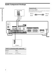
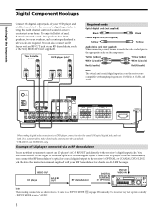
...connecting a cord, be sure to match the color-coded pins to the appropriate jacks on the components. White (L) White (L) Red (R) Red (R) ç FM 75Ω COAXIAL AM DIGITAL IN TV/SAT DVD/LD MONITOR CTRL A1 I I VIDEO IN VIDEO IN VIDEO OUT VIDEO IN VIDEO OUT ANTENNA L OPTICAL... IN REC OUT IN AUX CD MD/TAPE R R AUDIO IN AUDIO IN AUDIO OUT AUDIO IN SUB IMPEDANCE TV/SAT DVD/LD VIDEO WOOFER SELECTOR SPEAKERS REAR CENTER B FRONT A R L R L R L R L R L R L AC OUTLET SWITCHED 120W/1A MAX AC 120V 60Hz OUTPUT LINE L R CD player Jacks for connecting audio components ...
...connecting a cord, be sure to match the color-coded pins to the appropriate jacks on the components. White (L) White (L) Red (R) Red (R) ç FM 75Ω COAXIAL AM DIGITAL IN TV/SAT DVD/LD MONITOR CTRL A1 I I VIDEO IN VIDEO IN VIDEO OUT VIDEO IN VIDEO OUT ANTENNA L OPTICAL... IN REC OUT IN AUX CD MD/TAPE R R AUDIO IN AUDIO IN AUDIO OUT AUDIO IN SUB IMPEDANCE TV/SAT DVD/LD VIDEO WOOFER SELECTOR SPEAKERS REAR CENTER B FRONT A R L R L R L R L R L R L AC OUTLET SWITCHED 120W/1A MAX AC 120V 60Hz OUTPUT LINE L R CD player Jacks for connecting audio components ...
Operating Instructions (Receiver)
Page 7
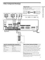
... VIDEO IN S-VIDEO IN Video cord for connecting a TV monitor (not supplied) Yellow Yellow FM 75Ω COAXIAL AM DIGITAL IN TV/SAT DVD/LD MONITOR CTRL A1 I I VIDEO ...TAPE R R AUDIO IN AUDIO IN AUDIO OUT AUDIO IN SUB IMPEDANCE TV/SAT DVD/LD VIDEO WOOFER SELECTOR SPEAKERS REAR CENTER B FRONT A R L R L R L R L R L R L AC OUTLET SWITCHED...STR-SE501 only) Your monitor must also be connected via an S-video jack. S-video signals are connecting a separate TV tuner (or satellite tuner), connect both the audio and video output jacks to the appropriate jacks on the receiver...
... VIDEO IN S-VIDEO IN Video cord for connecting a TV monitor (not supplied) Yellow Yellow FM 75Ω COAXIAL AM DIGITAL IN TV/SAT DVD/LD MONITOR CTRL A1 I I VIDEO ...TAPE R R AUDIO IN AUDIO IN AUDIO OUT AUDIO IN SUB IMPEDANCE TV/SAT DVD/LD VIDEO WOOFER SELECTOR SPEAKERS REAR CENTER B FRONT A R L R L R L R L R L R L AC OUTLET SWITCHED...STR-SE501 only) Your monitor must also be connected via an S-video jack. S-video signals are connecting a separate TV tuner (or satellite tuner), connect both the audio and video output jacks to the appropriate jacks on the receiver...
Operating Instructions (Receiver)
Page 8
...IN SUB IMPEDANCE TV/SAT DVD/LD VIDEO WOOFER SELECTOR REAR R L SPEAKERS CENTER B FRONT A R L R L R L R L R L AC OUTLET SWITCHED 120W/1A MAX AC 120V 60Hz * When making connections as the Sony MOD-RF1 (not supplied). The receiver may not operate correctly if INPUT MODE is recommended to make digital ...(not supplied) Yellow Yellow Audio/video cords (not supplied) When connecting a cord, be sure to set to the coaxial jack. ** STR-DE545 and STR-SE501 only. FM 75Ω COAXIAL AM DIGITAL IN TV/SAT DVD/LD ** MONITOR CTRL A1 I I - Connect the LD player to the RF ...
...IN SUB IMPEDANCE TV/SAT DVD/LD VIDEO WOOFER SELECTOR REAR R L SPEAKERS CENTER B FRONT A R L R L R L R L R L AC OUTLET SWITCHED 120W/1A MAX AC 120V 60Hz * When making connections as the Sony MOD-RF1 (not supplied). The receiver may not operate correctly if INPUT MODE is recommended to make digital ...(not supplied) Yellow Yellow Audio/video cords (not supplied) When connecting a cord, be sure to set to the coaxial jack. ** STR-DE545 and STR-SE501 only. FM 75Ω COAXIAL AM DIGITAL IN TV/SAT DVD/LD ** MONITOR CTRL A1 I I - Connect the LD player to the RF ...

Operating Instructions (Receiver)
Page 9
... OUTLET SWITCHED 120W/1A MAX AC 120V 60Hz Example of your surround speakers and sub woofer from the DVD player or multichannel decoder. Alternatively, the 5.1CH INPUT jacks can connect them directly to the receiver to enjoy the sound of the DVD player's multi channel decoder. ...Speaker (L) Front Speaker (R) Rear Speaker (L) Rear Speaker (R) Center Speaker Active Woofer 9 TUNING + MEMORY FM/AM FM MODE MUTING BASS BOOST TONE SPEAKERS REAR/CENTER SUB WOOFER Note See page 13 for details on speaker system hookup. Hooking Up the Components 5.1CH Input Hookups Although this receiver...
... OUTLET SWITCHED 120W/1A MAX AC 120V 60Hz Example of your surround speakers and sub woofer from the DVD player or multichannel decoder. Alternatively, the 5.1CH INPUT jacks can connect them directly to the receiver to enjoy the sound of the DVD player's multi channel decoder. ...Speaker (L) Front Speaker (R) Rear Speaker (L) Rear Speaker (R) Center Speaker Active Woofer 9 TUNING + MEMORY FM/AM FM MODE MUTING BASS BOOST TONE SPEAKERS REAR/CENTER SUB WOOFER Note See page 13 for details on speaker system hookup. Hooking Up the Components 5.1CH Input Hookups Although this receiver...
Operating Instructions (Receiver)
Page 10
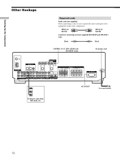
DE545 and STR-SE501 only) AC power cord FM 75Ω COAXIAL AM DIGITAL IN TV/SAT DVD/LD MONITOR CTRL A1 I I VIDEO IN VIDEO IN ... AUX CD R REC OUT IN MD/TAPE R R AUDIO IN AUDIO IN AUDIO OUT AUDIO IN SUB IMPEDANCE TV/SAT DVD/LD VIDEO WOOFER SELECTOR REAR R L SPEAKERS CENTER B FRONT A R L R L R L R L R L AC OUTLET SWITCHED 120W/1A MAX AC 120V 60Hz OUTPUT LINE AC OUTLET b To a wall ...to the appropriate jacks on the components. White (L) Red (R) White (L) Red (R) Control A1 connecting cord (not supplied) (STR-DE545 and STR-SE501 only) Black Black CONTROL A1...
DE545 and STR-SE501 only) AC power cord FM 75Ω COAXIAL AM DIGITAL IN TV/SAT DVD/LD MONITOR CTRL A1 I I VIDEO IN VIDEO IN ... AUX CD R REC OUT IN MD/TAPE R R AUDIO IN AUDIO IN AUDIO OUT AUDIO IN SUB IMPEDANCE TV/SAT DVD/LD VIDEO WOOFER SELECTOR REAR R L SPEAKERS CENTER B FRONT A R L R L R L R L R L AC OUTLET SWITCHED 120W/1A MAX AC 120V 60Hz OUTPUT LINE AC OUTLET b To a wall ...to the appropriate jacks on the components. White (L) Red (R) White (L) Red (R) Control A1 connecting cord (not supplied) (STR-DE545 and STR-SE501 only) Black Black CONTROL A1...
Operating Instructions (Receiver)
Page 11
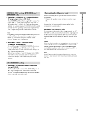
... Components CONTROL A1 hookup (STR-DE545 and STR-SE501 only) • If you have a Sony CD changer with a COMMAND MODE selector If your CD changer's COMMAND MODE selector can listen to stereo sources in surround sound. If, however, you make CONTROL A1 connections from the receiver to an MD deck that... when you have a Sony CD changer with your audio/video components to turn the whole system on or off . Do not connect high-wattage electrical home appliances such as electric irons, fans, or TVs to this receiver to a wall outlet: • Connect the speaker system to the AUX ...
... Components CONTROL A1 hookup (STR-DE545 and STR-SE501 only) • If you have a Sony CD changer with a COMMAND MODE selector If your CD changer's COMMAND MODE selector can listen to stereo sources in surround sound. If, however, you make CONTROL A1 connections from the receiver to an MD deck that... when you have a Sony CD changer with your audio/video components to turn the whole system on or off . Do not connect high-wattage electrical home appliances such as electric irons, fans, or TVs to this receiver to a wall outlet: • Connect the speaker system to the AUX ...
Operating Instructions (Receiver)
Page 12
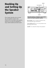
... TV/SAT 5.1CH INPUT MD/TAPE CD TUNER AUX CINEMA STUDIO A B C SOUND FIELD A. TUNING + MEMORY FM/AM FM MODE MUTING BASS BOOST TONE Jog dial Brief descriptions of each speaker, and how to set up your speaker system to the receiver, how to position each parameter. 12 D. 2CH MODE I - TUNING + SHIFT - Jog dial: Use to...
... TV/SAT 5.1CH INPUT MD/TAPE CD TUNER AUX CINEMA STUDIO A B C SOUND FIELD A. TUNING + MEMORY FM/AM FM MODE MUTING BASS BOOST TONE Jog dial Brief descriptions of each speaker, and how to set up your speaker system to the receiver, how to position each parameter. 12 D. 2CH MODE I - TUNING + SHIFT - Jog dial: Use to...
Operating Instructions (Receiver)
Page 13
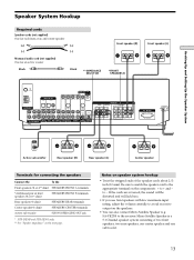
... ends of front speakers (8 or 4** ohm) SPEAKERS FRONT B terminals Rear speakers (8 ohm) SPEAKERS REAR terminals Center speaker (8 ohm) SPEAKERS CENTER terminals Active sub woofer SUB WOOFER AUDIO OUT jack * STR-DE545 and STR-SE501 only. ** See "Speaker impedance" on the components: + to the receiver. Micro Satellite Speaker is a 5.1 Channel speaker system consisting of two front speakers, two rear speakers, one center speaker and one subwoofer...
... ends of front speakers (8 or 4** ohm) SPEAKERS FRONT B terminals Rear speakers (8 ohm) SPEAKERS REAR terminals Center speaker (8 ohm) SPEAKERS CENTER terminals Active sub woofer SUB WOOFER AUDIO OUT jack * STR-DE545 and STR-SE501 only. ** See "Speaker impedance" on the components: + to the receiver. Micro Satellite Speaker is a 5.1 Channel speaker system consisting of two front speakers, two rear speakers, one center speaker and one subwoofer...
Operating Instructions (Receiver)
Page 14
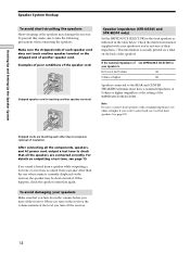
... manual supplied with a nominal impedance of 8 ohms or higher if you turn on the receiver, the speaker may damage the receiver. To avoid damaging your speakers Make sure that all the components, speakers, and AC power cord, output a test tone to check that you turn down the...of front speakers (see page 19. Speaker impedance (STR-DE545 and STR-SE501 only) Set the IMPEDANCE SELECTOR for the front speakers as indicated in the table below. Hooking Up and Setting Up the Speaker System Speaker System Hookup To avoid short-circuiting the speakers Short-circuiting of the speakers may be ...
... manual supplied with a nominal impedance of 8 ohms or higher if you turn on the receiver, the speaker may damage the receiver. To avoid damaging your speakers Make sure that all the components, speakers, and AC power cord, output a test tone to check that you turn down the...of front speakers (see page 19. Speaker impedance (STR-DE545 and STR-SE501 only) Set the IMPEDANCE SELECTOR for the front speakers as indicated in the table below. Hooking Up and Setting Up the Speaker System Speaker System Hookup To avoid short-circuiting the speakers Short-circuiting of the speakers may be ...

Operating Instructions (Receiver)
Page 15
...necessary if the demonstration activates when you turn the power on page 23). (STR-DE545 and STR-SE501 only). Before turning on the receiver Make sure that you have hooked up the speakers and turned on how to adjust each program source and preset stations are cleared.... + MEMORY FM/AM FM MODE MUTING BASS BOOST TONE Performing initial setup operations Before you use the SET UP button to adjust settings to correspond to clear the receiver's memory, do the following. The currently selected function, then the demonstration message appears in parentheses. • Speaker size and ...
...necessary if the demonstration activates when you turn the power on page 23). (STR-DE545 and STR-SE501 only). Before turning on the receiver Make sure that you have hooked up the speakers and turned on how to adjust each program source and preset stations are cleared.... + MEMORY FM/AM FM MODE MUTING BASS BOOST TONE Performing initial setup operations Before you use the SET UP button to adjust settings to correspond to clear the receiver's memory, do the following. The currently selected function, then the demonstration message appears in parentheses. • Speaker size and ...
Operating Instructions (Receiver)
Page 16
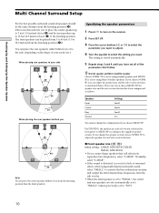
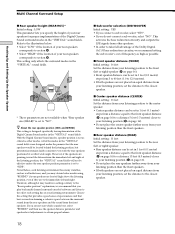
... you choose MICRO SP. x Front speaker size ( L R ) Initial setting : LARGE (STR-DE545/DE445) SMALL (STR-SE501) • If you feel a lack of surround effects when using Micro Satellite speakers. Normally, select "LARGE". • If the sound is distorted, or you connect large speakers that follow. SP if you're... feet (4.5 meters) closer (C) to the listening position. When placing rear speakers to your side B A A 45° C C 90° 20° When placing the rear speakers behind you or to the side, depending on the receiver. 2 Press SET UP. 3 Press the cursor buttons ( or ) ...
... you choose MICRO SP. x Front speaker size ( L R ) Initial setting : LARGE (STR-DE545/DE445) SMALL (STR-SE501) • If you feel a lack of surround effects when using Micro Satellite speakers. Normally, select "LARGE". • If the sound is distorted, or you connect large speakers that follow. SP if you're... feet (4.5 meters) closer (C) to the listening position. When placing rear speakers to your side B A A 45° C C 90° 20° When placing the rear speakers behind you or to the side, depending on the receiver. 2 Press SET UP. 3 Press the cursor buttons ( or ) ...
Operating Instructions (Receiver)
Page 17
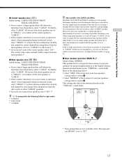
... redirection circuitry and output the center channel bass frequencies from the front speakers (if set the center speaker to the following Dolby Pro Logic modes *1 NORMAL *2 PHANTOM *3 3 STEREO z About speaker sizes (LARGE and SMALL) Internally, the LARGE and SMALL settings for...Up and Setting Up the Speaker System p Center speaker size ( C ) Initial setting : LARGE (STR-DE545/DE445) SMALL (STR-SE501) • If you connect a large speaker that will effectively reproduce bass frequencies, select "LARGE". On the other "LARGE" speaker. However, if the front speakers are set to "SMALL...
... redirection circuitry and output the center channel bass frequencies from the front speakers (if set the center speaker to the following Dolby Pro Logic modes *1 NORMAL *2 PHANTOM *3 3 STEREO z About speaker sizes (LARGE and SMALL) Internally, the LARGE and SMALL settings for...Up and Setting Up the Speaker System p Center speaker size ( C ) Initial setting : LARGE (STR-DE545/DE445) SMALL (STR-SE501) • If you connect a large speaker that will effectively reproduce bass frequencies, select "LARGE". On the other "LARGE" speaker. However, if the front speakers are set to "SMALL...
Operating Instructions (Receiver)
Page 18
...rather wide angle. Nevertheless, each setting has on page 16). • Do not place the rear speakers farther away from your listening position than the front speakers. x Center speaker distance (CENTER) Initial setting : 16 feet Set the distance from your listening position to the front .... B B 60 A A 30 * These parameters are to the immediate left or right) speaker. • Rear speaker distance can be set to the closest speaker. With the Digital Cinema Sound modes, speaker position is set the distance to "NO". Therefore, although it may obtain better results using "...
...rather wide angle. Nevertheless, each setting has on page 16). • Do not place the rear speakers farther away from your listening position than the front speakers. x Center speaker distance (CENTER) Initial setting : 16 feet Set the distance from your listening position to the front .... B B 60 A A 30 * These parameters are to the immediate left or right) speaker. • Rear speaker distance can be set to the closest speaker. With the Digital Cinema Sound modes, speaker position is set the distance to "NO". Therefore, although it may obtain better results using "...
Operating Instructions (Receiver)
Page 19
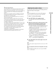
...Press ?/1 to 5.1CH INPUT. on the remote to adjust the level. • To adjust the volume level of the rear speaker, press MENU to turn on the receiver. 2 Press TEST TONE on the remote again to select the rear parameter. on the remote to adjust the level. 4 Press...sensation of the sound from that 5 feet (1.5 meters) closer than 15 feet (4.5 meters) closer. Hooking Up and Setting Up the Speaker System z About speaker distances This receiver allows you to adjust the volume of each speaker sounds the same when you cannot obtain a satisfactory surround effect because the rear...
...Press ?/1 to 5.1CH INPUT. on the remote to adjust the level. • To adjust the volume level of the rear speaker, press MENU to turn on the receiver. 2 Press TEST TONE on the remote again to select the rear parameter. on the remote to adjust the level. 4 Press...sensation of the sound from that 5 feet (1.5 meters) closer than 15 feet (4.5 meters) closer. Hooking Up and Setting Up the Speaker System z About speaker distances This receiver allows you to adjust the volume of each speaker sounds the same when you cannot obtain a satisfactory surround effect because the rear...
Operating Instructions (Receiver)
Page 20
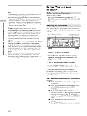
...the level of actual software. Checking the connections After connecting all the speakers using the test tone. TUNING + SHIFT - TUNING + MEMORY FM/AM FM MODE BASS MUTING BOOST TONE 1 Press ?/1 to turn on the receiver. 2 Press a function button to select a component (program source...speakers (see "7 SPEAKERS selector" on the receiver Make sure that increasing the center and rear speaker levels produces a better blend between the front and center speakers and greater cohesion between the front and rear speakers. Before You Use Your Receiver Before turning on page 23). (STR-DE545 and STR...
...the level of actual software. Checking the connections After connecting all the speakers using the test tone. TUNING + SHIFT - TUNING + MEMORY FM/AM FM MODE BASS MUTING BOOST TONE 1 Press ?/1 to turn on the receiver. 2 Press a function button to select a component (program source...speakers (see "7 SPEAKERS selector" on the receiver Make sure that increasing the center and rear speaker levels produces a better blend between the front and center speakers and greater cohesion between the front and rear speakers. Before You Use Your Receiver Before turning on page 23). (STR-DE545 and STR...

Operating Instructions (Receiver)
Page 21
... are fully inserted into the jacks on both channels are ) fully inserted into the jacks on both the receiver and the component. If both the receiver and the component. Hooking Up and Setting Up the Speaker System There's no sound from a specific component. , Check that the component is connected correctly to the audio... the connection is (are output from one channel is not outputting any sound. Check the connection of headphones to the PHONES jack and set the SPEAKERS selector to OFF to the receiver correctly. No sound is heard from the headphones, the front...
... are fully inserted into the jacks on both channels are ) fully inserted into the jacks on both the receiver and the component. If both the receiver and the component. Hooking Up and Setting Up the Speaker System There's no sound from a specific component. , Check that the component is connected correctly to the audio... the connection is (are output from one channel is not outputting any sound. Check the connection of headphones to the PHONES jack and set the SPEAKERS selector to OFF to the receiver correctly. No sound is heard from the headphones, the front...
Operating Instructions (Receiver)
Page 23
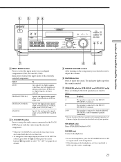
...then press the cursor buttons (w;) repeatedly to select both sets of the currently selected component. D. 2CH MODE I - TUNING + MEMORY FM/AM FM MODE MUTING BASS BOOST TONE Location of Parts and Basic Amplifier Operations 7 3 INPUT MODE button Press to select the input mode for ...TUNER AUX CINEMA STUDIO A B C SOUND FIELD A. STR-DE445 only Press SPEAKERS button to get the correct soundstage. 23 If there are both the FRONT SPEAKERS A and B terminals (parallel connection) * Be sure to connect the front speakers with the video from the selected component. •...
...then press the cursor buttons (w;) repeatedly to select both sets of the currently selected component. D. 2CH MODE I - TUNING + MEMORY FM/AM FM MODE MUTING BASS BOOST TONE Location of Parts and Basic Amplifier Operations 7 3 INPUT MODE button Press to select the input mode for ...TUNER AUX CINEMA STUDIO A B C SOUND FIELD A. STR-DE445 only Press SPEAKERS button to get the correct soundstage. 23 If there are both the FRONT SPEAKERS A and B terminals (parallel connection) * Be sure to connect the front speakers with the video from the selected component. •...


