
Service Manual
Page 1
...75 ohms 76 dB 70 dB 0.3% 0.5% 45 dB at 1 kHz 30 Hz - 15 kHz, +0.5/-2 dB 60 dB at 400 kHz - SERVICE MANUAL Ver. 1.5 2007. 05 STR-DE197 US Model Canadian Model AEP Model AUDIO POWER SPECIFICATIONS POWER OUTPUT AND TOTAL HARMONIC DISTORTION: (Models of ar ea code AEP Power Output a t ...both channels driven, from 250 milliwatts to rated output. Continued on next page - FM STEREO/FM-AM RECEIVER 9-877-864-06 2007E04-1 © 2007. 05 Sony Corporation Home Audio Division Published by Sony Techno Create Corporation 1 rated 100 watts per channel minimum RMS power, with bass boost and tone b ...
...75 ohms 76 dB 70 dB 0.3% 0.5% 45 dB at 1 kHz 30 Hz - 15 kHz, +0.5/-2 dB 60 dB at 400 kHz - SERVICE MANUAL Ver. 1.5 2007. 05 STR-DE197 US Model Canadian Model AEP Model AUDIO POWER SPECIFICATIONS POWER OUTPUT AND TOTAL HARMONIC DISTORTION: (Models of ar ea code AEP Power Output a t ...both channels driven, from 250 milliwatts to rated output. Continued on next page - FM STEREO/FM-AM RECEIVER 9-877-864-06 2007E04-1 © 2007. 05 Sony Corporation Home Audio Division Published by Sony Techno Create Corporation 1 rated 100 watts per channel minimum RMS power, with bass boost and tone b ...

Service Manual
Page 2
...REPLACE THESE COMPONENTS WITH SONY PARTS WHOSE PART NUMBERS APPEAR AS SHOWN IN THIS MANUAL OR IN SUPPLEMENTS PUBLISHED BY SONY. 2 ATTENTION AU...SONY. To reset the scale to 9 kHz or 10 kHz. Leakage current can change the AM tuning scale to 10 kHz (or 9 kHz), repeat the procedure. A. STR-DE197... CND: Canadian model SAFETY CHECK-OUT After correcting the original service problem, perform the following safety check before releasing the set to...Measuring the voltage drop across a resistor by any AM station, turn off the receiver. A) To Exposed Metal Parts on Set 0.15 µF 1.5 kΩ...
...REPLACE THESE COMPONENTS WITH SONY PARTS WHOSE PART NUMBERS APPEAR AS SHOWN IN THIS MANUAL OR IN SUPPLEMENTS PUBLISHED BY SONY. 2 ATTENTION AU...SONY. To reset the scale to 9 kHz or 10 kHz. Leakage current can change the AM tuning scale to 10 kHz (or 9 kHz), repeat the procedure. A. STR-DE197... CND: Canadian model SAFETY CHECK-OUT After correcting the original service problem, perform the following safety check before releasing the set to...Measuring the voltage drop across a resistor by any AM station, turn off the receiver. A) To Exposed Metal Parts on Set 0.15 µF 1.5 kΩ...

Service Manual
Page 33
... inspection, check the part number of new type, and changed parts list are described in this supplement with the service manual. DISCRIMINATION - DISPLAY BOARD (COMPONENT SIDE) - STR-DE197 SERVICE MANUAL Ver. 1.3 2006. 09 US Model Canadian Model AEP Model SUPPLEMENT-1 File this Supplement-1. Former : 1-861-586-11 New : 1-871-791-11 9-877-864-81 1 MAIN ...
... inspection, check the part number of new type, and changed parts list are described in this supplement with the service manual. DISCRIMINATION - DISPLAY BOARD (COMPONENT SIDE) - STR-DE197 SERVICE MANUAL Ver. 1.3 2006. 09 US Model Canadian Model AEP Model SUPPLEMENT-1 File this Supplement-1. Former : 1-861-586-11 New : 1-871-791-11 9-877-864-81 1 MAIN ...

Service Manual
Page 36
...Location D-6 D-6 E-9 C-6 C-6 D-6 D-6 E-9 E-9 D-6 D-10 B-8 B-9 B-8 B-8 B-8 B-8 Ref. MAIN SECTION - • Refer to page 13 of Service Manual for Circuit Boards Location. : Uses unleaded solder. 1 2 3 4 5 6 7 8 9 10 11 A J801 J802 TM801 B C D E F ... Q901 Q902 Q903 Q904 (Q905) (Q906) Location F-7 F-7 F-8 E-7 E-7 D-9 E-8 E-8 D-6 D-6 D-5 B-8 B-9 D-9 E-8 E-2 D-2 ( ) : AEP model only STR-DE197 4 4 No. PRINTED WIRING BOARDS - IC901 IC902 IC903 IC904 (IC905) IC906 (IC907) Location C-9 D-9 C-4 C-2 E-2 E-2 E-8 Q424 C-5 Q474 C-5 Q701 E-4 Q702 F-4 Q703 F-4 Q704 F-5...
...Location D-6 D-6 E-9 C-6 C-6 D-6 D-6 E-9 E-9 D-6 D-10 B-8 B-9 B-8 B-8 B-8 B-8 Ref. MAIN SECTION - • Refer to page 13 of Service Manual for Circuit Boards Location. : Uses unleaded solder. 1 2 3 4 5 6 7 8 9 10 11 A J801 J802 TM801 B C D E F ... Q901 Q902 Q903 Q904 (Q905) (Q906) Location F-7 F-7 F-8 E-7 E-7 D-9 E-8 E-8 D-6 D-6 D-5 B-8 B-9 D-9 E-8 E-2 D-2 ( ) : AEP model only STR-DE197 4 4 No. PRINTED WIRING BOARDS - IC901 IC902 IC903 IC904 (IC905) IC906 (IC907) Location C-9 D-9 C-4 C-2 E-2 E-2 E-8 Q424 C-5 Q474 C-5 Q701 E-4 Q702 F-4 Q703 F-4 Q704 F-5...

Service Manual
Page 39
...Location D201 C-1 D202 D-2 D203 D-2 D204 C-3 D205 G-1 D206 F-1 IC201 C-6 IC202 D-4 Q201 C-3 Q202 C-3 Q204 G-1 Q205 F-1 Q206 E-3 PANEL SECTION - • Refer to page 13 of Service Manual for Circuit Boards Location. : Uses unleaded solder. 1 2 3 4 5 6 7 8 9 10 11 12 13 14 A B C D E S221 S215 S217 R276 S219 S218 R277 R275 S216... R259 S235 R258 S234 R257 S233 R256 S232 ((Page 4)) F S203 R297 Q205 D206 S202 CNP201 Q204 G D205 R289 R290 H S201 STR-DE197 7 7 • Semiconductor Location Ref. STR-DE197 4. PRINTED WIRING BOARDS -
...Location D201 C-1 D202 D-2 D203 D-2 D204 C-3 D205 G-1 D206 F-1 IC201 C-6 IC202 D-4 Q201 C-3 Q202 C-3 Q204 G-1 Q205 F-1 Q206 E-3 PANEL SECTION - • Refer to page 13 of Service Manual for Circuit Boards Location. : Uses unleaded solder. 1 2 3 4 5 6 7 8 9 10 11 12 13 14 A B C D E S221 S215 S217 R276 S219 S218 R277 R275 S216... R259 S235 R258 S234 R257 S233 R256 S232 ((Page 4)) F S203 R297 Q205 D206 S202 CNP201 Q204 G D205 R289 R290 H S201 STR-DE197 7 7 • Semiconductor Location Ref. STR-DE197 4. PRINTED WIRING BOARDS -
Service Manual
Page 49
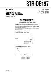
... schematic diagram of new type, and changed parts list are described in this supplement with the service manual. MAIN BOARD (COMPONENT SIDE) - DISPLAY BOARD Part No. 1-861-586-1 : Service Manual 1-871-791-1 :Supplement-1 1-861-586-2 :Supplement-2 9-877-864-82 1 STR-DE197 SERVICE MANUAL Ver. 1.4 2007. 03 US Model Canadian Model AEP Model SUPPLEMENT-2 File this Supplement-2. DISCRIMINATION - When...
... schematic diagram of new type, and changed parts list are described in this supplement with the service manual. MAIN BOARD (COMPONENT SIDE) - DISPLAY BOARD Part No. 1-861-586-1 : Service Manual 1-871-791-1 :Supplement-1 1-861-586-2 :Supplement-2 9-877-864-82 1 STR-DE197 SERVICE MANUAL Ver. 1.4 2007. 03 US Model Canadian Model AEP Model SUPPLEMENT-2 File this Supplement-2. DISCRIMINATION - When...

Service Manual
Page 52
... E-2 Q424 C-5 Q474 C-5 Q701 E-4 Q702 F-4 Q703 F-4 Q704 F-5 Q705 E-5 Q706 E-6 Q751 E-7 Ref. No. Location Ref. No. MAIN SECTION - • Refer to page 13 of Service Manual for Circuit Boards Location. : Uses unleaded solder. 1 2 3 4 5 6 7 8 9 10 11 A J801 J802 TM801 B C D E F JW500 JW461 JW480 D904 D903 C902 D901... Q756 Q781 Q782 Q783 Q784 Q785 Q786 Q901 Q902 Q903 Q904 Location F-7 F-7 F-8 E-7 E-7 D-9 E-8 E-8 D-6 D-6 D-5 B-8 B-9 D-9 E-8 STR-DE197 4 4 1-861-590J803 T901 G • Semiconductor Location Ref. PRINTED WIRING BOARDS -
... E-2 Q424 C-5 Q474 C-5 Q701 E-4 Q702 F-4 Q703 F-4 Q704 F-5 Q705 E-5 Q706 E-6 Q751 E-7 Ref. No. Location Ref. No. MAIN SECTION - • Refer to page 13 of Service Manual for Circuit Boards Location. : Uses unleaded solder. 1 2 3 4 5 6 7 8 9 10 11 A J801 J802 TM801 B C D E F JW500 JW461 JW480 D904 D903 C902 D901... Q756 Q781 Q782 Q783 Q784 Q785 Q786 Q901 Q902 Q903 Q904 Location F-7 F-7 F-8 E-7 E-7 D-9 E-8 E-8 D-6 D-6 D-5 B-8 B-9 D-9 E-8 STR-DE197 4 4 1-861-590J803 T901 G • Semiconductor Location Ref. PRINTED WIRING BOARDS -

Service Manual
Page 55
... 4)) S236 R261 CNP200 R260 R259 S235 R258 S234 R257 S233 R256 S232 1-861-588- R289 R290 H S201 1-861-591- STR-DE197 4. STR-DE197 7 7 • Semiconductor Location Ref. PANEL SECTION - • Refer to page 13 of Service Manual for Circuit Boards Location. : Uses unleaded solder. 1 2 3 4 5 6 7 8 9 10 11 12 13 14 A B C D E F G Q204 Q205 S221 S219 S220 S215 S217...
... 4)) S236 R261 CNP200 R260 R259 S235 R258 S234 R257 S233 R256 S232 1-861-588- R289 R290 H S201 1-861-591- STR-DE197 4. STR-DE197 7 7 • Semiconductor Location Ref. PANEL SECTION - • Refer to page 13 of Service Manual for Circuit Boards Location. : Uses unleaded solder. 1 2 3 4 5 6 7 8 9 10 11 12 13 14 A B C D E F G Q204 Q205 S221 S219 S220 S215 S217...


